EP1304663A2 - Münzspeicher - Google Patents
Münzspeicher Download PDFInfo
- Publication number
- EP1304663A2 EP1304663A2 EP02450239A EP02450239A EP1304663A2 EP 1304663 A2 EP1304663 A2 EP 1304663A2 EP 02450239 A EP02450239 A EP 02450239A EP 02450239 A EP02450239 A EP 02450239A EP 1304663 A2 EP1304663 A2 EP 1304663A2
- Authority
- EP
- European Patent Office
- Prior art keywords
- coin
- removal
- storage
- slot
- coins
- Prior art date
- Legal status (The legal status is an assumption and is not a legal conclusion. Google has not performed a legal analysis and makes no representation as to the accuracy of the status listed.)
- Withdrawn
Links
Images


Classifications
-
- G—PHYSICS
- G07—CHECKING-DEVICES
- G07D—HANDLING OF COINS OR VALUABLE PAPERS, e.g. TESTING, SORTING BY DENOMINATIONS, COUNTING, DISPENSING, CHANGING OR DEPOSITING
- G07D9/00—Counting coins; Handling of coins not provided for in the other groups of this subclass
- G07D9/002—Coin holding devices
-
- A—HUMAN NECESSITIES
- A45—HAND OR TRAVELLING ARTICLES
- A45C—PURSES; LUGGAGE; HAND CARRIED BAGS
- A45C1/00—Purses; Money-bags; Wallets
- A45C1/10—Money-bags for conductors or like people; Money-bags with rigid coin-holders
-
- A—HUMAN NECESSITIES
- A45—HAND OR TRAVELLING ARTICLES
- A45C—PURSES; LUGGAGE; HAND CARRIED BAGS
- A45C1/00—Purses; Money-bags; Wallets
- A45C1/10—Money-bags for conductors or like people; Money-bags with rigid coin-holders
- A45C2001/102—Rigid coin-holders
- A45C2001/107—Rigid coin-holders with coins stored in piles, i.e. several coins stacked in a compartment
Definitions
- the invention relates to a coin store according to the preamble of the claim 1.
- the invention aims to be a compact, structurally simple and to create stable coin storage, especially for storing coins different values or different diameters is suitable and this Holds coins securely if no withdrawal is to take place, but during withdrawal issues these coins with little effort and effort.
- a viewing opening formed by the application of the finger by the Coin operated opening on the downward-facing surface of the coin. This Viewing opening also serves to determine whether there is still a certain minimum number of Coins are located in the respective storage chute.
- Fig. 1 shows a perspective view of a coin storage obliquely from above.
- Fig. 2 shows a perspective view of a coin storage obliquely from below.
- Fig. 3 shows a detailed view of a removal area,
- Fig. 4 shows different views of a coin store according to the invention in different cuts.
- Fig. 5 shows different views of a lid for coin storage according to the invention.
- FIG. 1 is a schematic, perspective view of an inventive Coin storage 1 shown.
- a number of storage shafts 3 is located in a housing 2 trained, which serve to receive coins 14.
- the individual storage bays 3 in particular have different diameters to make coins different To be able to record or save values.
- the task ends 17 the Storage shafts 3 are closed with a lid 10, in the slot 11 for the coins 14 to be stored are formed.
- each Storage shaft 3 is a, preferably circular, support surface or Support surface 5 formed, which prevents the stored coins from falling out.
- the lowest coin 14 of each stack of coins lies on this support surface 5.
- This Contact surface delimits a coin actuation opening 7, through which opening 7 the after surface of the coin protruding below with the finger or the coin 14 through a removal slot 4 can be carried out in the side area of each Storage shaft 3 is formed.
- the housing 2 is in the area between the Removal slot 4 and the lower end portion of the housing 2 except, and the Coin actuation opening 7 merges into a viewing opening 8 via this recess 15. This recess 15 interrupts the contact surface 6.
- the storage shafts 3 are in the housing 2 with a small wall distance arranged side by side in order to save a space-saving coin storage 1 create.
- counting or viewing recesses 9 are formed, which provide insight into the Storage bays 3 allow to determine how many coins in these bays 3 are included.
- these recesses 9 can be omitted or replaced by markings.
- This Recesses and / or the markings are at a distance from the Contact surface 5, which is an integer multiple of the thickness of the respective Storage slot 3 corresponds to the coins to be stored.
- Fig. 2 shows a perspective rear view of an inventive Coin storage from below.
- supporting parts 12 in particular loops, for belt attachment of the coin store 1.
- the lower end region of the coin actuation opening 7 beveled to achieve a certain guidance of the finger with which the lowest coin 14 raised and moved in the direction of the removal slot 4 or out the removal slot 4 is to be led out.
- the bevel is at 16 designated.
- the recess 15 advantageously has a width such that a finger or a fingertip placed on the bottom coin can pass through.
- Fig. 3 shows the area of the removal end 18 in which the respective Storage shaft 3 passes into the coin actuation opening 7.
- the removal slot 4 has a height H and an inner, the feed end of the respective storage shaft 3 distant edge 19. This inner edge 19 delimits a contact surface or a wall section 6 with a height A and merges into the support or support surface 5.
- the height H of the removal slot is 4 dimensioned such that entry of the coin resting on the lowest coin 14 not possible. Only by lifting the bottom coin 14 can this in the Enter removal slot 4.
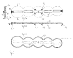
- 4 shows various representations of the coin container according to the invention.
- 4c shows a rear view from which the housing 2 and the support devices 12 are evident.
- FIG. 4a shows a bottom view of a coin container as shown in FIG. 4b.
- Fig. 4d shows a schematic section transverse to the longitudinal extension of the Coin container 1 according to the invention according to FIG. 4a.
- Fig. 4h shows a section according to A-A of Fig. 4i.
- Fig. 4e shows a top view a coin container 1, with the cover removed. You can see the storage bays 3, which have different diameters and at the bottom of the support surface 5 are limited.
- 4f shows a side view of a coin container 2 according to the invention and
- Fig. 4g shows a sectional view along the line B-B in Fig. 4e.
- FIG. 5 is a cover 10 for closing the coin store according to the invention 1 shown.
- Fig. 5b shows a side view of a cover 10, in which one of the number the storage shafts 3 corresponding number of insertion slots 11 is formed. With latching or clamping extensions 13, the cover 10 is fixed on the housing 2, on the corresponding counter detents are provided or formed.
- 5a shows one Bottom view and
- Fig. 5c shows a plan view of the lid 10.
- Fig. 5d shows a section along C-C from Fig. 5a.
- Five to eight storage wells 3 are advantageously arranged side by side arranged, with wall distances of about 3 to 6 mm, resulting in a compact Construction results.
- the peculiarity of the invention is that the coins 14 are not can fall out of the coin store 1 because the lowest coin is about 0.8 to 1.2 mm comes to lie under the removal slot 4 with its lower edge and thus the subsequent coin in the stack cannot pass through the removal slot 4 since they also only with a partial area of their thickness in the area of the removal slot 4 comes to lie.
- the level in which these two coins lie against each other is located somewhere between the two, i.e. the lower and upper trailing edge (s) of the Removal slot 4; this range is advantageously in the middle third or in the two middle quarters of the height of the removal slot 4.
- a removal of the lowest coin is done by lifting the coin slightly with a finger, below Pulling the coin forward with this finger, at most the index finger and the thumb. Without such raising and pulling out the bottom coin, there is none Possibility of taking out a coin or accidentally falling out.
- the height the removal slot 4 is advantageously 2 to 2.5 mm, in particular 2 to 2.3 mm.
- each removal slot 4 advantageously rounded, in particular semicircular viewing opening 8 serves to facilitate removal of coins.
- the overall height of the coin store 1 can be changed as desired or can be adapted to the desired use.
- the coin store 1 is characterized in that it consists exclusively of two parts, namely the housing 2 and the cover 10 and otherwise has no other moving or mechanical parts.
- the coin store 1 is light on the belt, always ready to hand. This makes dealing with them too coins, especially EUROs, especially the issuance of Change, much easier.
- the field of application is such Coin storage can be seen in the restaurant business.
- Each is located on the front for practical handling Storage shaft 3 a scale or viewing window with which the number or the amount the coins located in the respective collecting shaft 3 are easily recognizable.
- the storage wells 3 could also have a square cross section exhibit.
- the bearing surface 5 can consist of several surface parts or of a circular ring are formed, advantageously a recess 15 in the area of Removal end 18 is present.
Landscapes
- Physics & Mathematics (AREA)
- General Physics & Mathematics (AREA)
- Purses, Travelling Bags, Baskets, Or Suitcases (AREA)
Abstract
Description
Claims (7)
- Münzspeicher (1) mit einer Anzahl von in einem Gehäuse (2) ausgebildeten, voneinander separierten, insbesondere unterschiedlichen Durchmesser aufweisenden, vorzugsweise zylindrischen, im Gebrauch insbesondere vertikal oder annähernd vertikal ausgerichteten Speicherschächten (3) für insbesondere unterschiedliche Durchmesser aufweisende Münzen (14), welche Speicherschächte (3) ein Aufgabeende (17) und ein Entnahmeende (18) aufweisen, wobei in dem im Gebrauch vorzugsweise unten liegenden Entnahmeende (18) jedes Speicherschachtes (3) ein sich seitlich öffnender und in den Speicherschacht (3) mündender, die Entnahme einer Münze zulassender Entnahmeschlitz (4) ausgebildet ist, und wobei jeder Speicherschacht (3) im Entnahmeende (18) längs seines Innenumfanges mit zumindest einer, die jeweils unterste Münze (14) eines im Speicherschacht (3) angeordneten Münzstapels abstützenden, Endauflage- bzw. Stützfläche (5) versehen ist, die nach innen ragt und eine vorzugsweise mittig liegende Münzbetätigungsöffnung (7) begrenzt bzw. freilässt, durch welche Münzbetätigungsöffnung (7) der Speicherschacht (3) zugängig bzw. die unterste Münze (14) angreifbar ist, dadurch gekennzeichnet, dass der Entnahmeschlitz (4), insbesondere dessen dem Aufgabeende (17) ferne Kante (19), im jeweiligen Speicherschacht (3) im Abstand (A) von der Endauflage- bzw. Stützfläche (5) gelegen ist, wobei dieser Abstand (A) kleiner bemessen ist als die Dicke (D) der in diesem Speicherschacht (3) zu speichernden Münzen (14) und dass der, zwischen der Kante (19) des Entnahmeschlitzes (4) und der Endauflage- bzw. Stützfläche (5) vorhandene Wandabschnitt des Speicherschachtes (3) als Anlage- bzw. Rückhaltefläche (6) für die unterste Münze (14) vorgesehen ist.
- Münzspeicher nach Anspruch 1, dadurch gekennzeichnet, dass die Münzbetätigungsöffnung (7) sich vom unteren Ende bzw. vom Entnahmeende (18) des Speicherschachtes (3) in den Seitenbereich des Gehäuses (2), in dem der Entnahmeschlitz (4) ausgebildet ist, erstreckt bzw. öffnet und sich über diesen Entnahmeschlitz (4), insbesondere mittig, hinaus erstreckt, und in diesem Bereich eine Sichtöffnung (8) ausbildet.
- Münzspeicher nach Anspruch 1 oder 2, dadurch gekennzeichnet, dass die Höhe (A) des Wandabschnittes bzw. der Anlagefläche (6) 20 bis 70 %, vorzugsweise 35 bis 60 %, der Höhe (H) des Entnahmeschlitzes (4) beträgt.
- Münzspeicher nach einem der Ansprüche 1 bis 3, dadurch gekennzeichnet, dass die Höhe (H) des Entnahmeschlitzes (4) 110 bis 160 %, vorzugsweise 120 bis 150 %, der Dicke (D) der in dem Speicherschacht (3) zu speichernden Münzen (14) beträgt.
- Münzspeicher nach einem der Ansprüche 1 bis 4, dadurch gekennzeichnet, dass das Gehäuse (2) und/oder der Deckel (10) des Münzspeichers (1) aus Kunststoff, insbesondere durchsichtigem Kunststoff, gefertigt sind und dass in dem Gehäuse (2) in die jeweiligen Speicherschächte (3) führende, in zueinander gleichen, einem ganzzahligen Vielfachen der Dicke (D) der Münzen (14) entsprechenden, Abständen angeordnete Zähl- bzw. Sichtausnehmungen (9) ausgebildet sind.
- Münzspeicher nach einem der Ansprüche 1 bis 5, dadurch gekennzeichnet, dass der Entnahmeschlitz (4) im wesentlichen senkrecht zur Längsachse des Speicherschachtes (3) ausgerichtet ist.
- Münzspeicher nach einem der Ansprüche 1 bis 6, dadurch gekennzeichnet, dass sich der Entnahmeschlitz (4) nach innen zu erweitert, wobei insbesondere die dem Aufgabeende (17) nahe Innenfläche des Entnahmeschlitzes (4) geneigt verläuft.
Applications Claiming Priority (4)
| Application Number | Priority Date | Filing Date | Title |
|---|---|---|---|
| AT16702001 | 2001-10-19 | ||
| AT16702001 | 2001-10-19 | ||
| AT19752001A AT410852B (de) | 2001-10-19 | 2001-12-17 | Münzspeicher |
| AT19752001 | 2001-12-17 |
Publications (2)
| Publication Number | Publication Date |
|---|---|
| EP1304663A2 true EP1304663A2 (de) | 2003-04-23 |
| EP1304663A3 EP1304663A3 (de) | 2004-09-22 |
Family
ID=25608534
Family Applications (1)
| Application Number | Title | Priority Date | Filing Date |
|---|---|---|---|
| EP02450239A Withdrawn EP1304663A3 (de) | 2001-10-19 | 2002-10-17 | Münzspeicher |
Country Status (2)
| Country | Link |
|---|---|
| EP (1) | EP1304663A3 (de) |
| AT (1) | AT410852B (de) |
Family Cites Families (8)
| Publication number | Priority date | Publication date | Assignee | Title |
|---|---|---|---|---|
| US416551A (en) * | 1889-12-03 | Coin-holder | ||
| US916293A (en) * | 1908-06-30 | 1909-03-23 | William H Garland | Coin-holder. |
| US954761A (en) * | 1909-03-03 | 1910-04-12 | Charles G Palmer | Change-carrier. |
| US1438135A (en) * | 1921-06-22 | 1922-12-05 | John D Pettit | Coin till |
| US1900798A (en) * | 1930-06-25 | 1933-03-07 | Reginald J Chappell | Game appliance |
| US3449034A (en) * | 1966-07-25 | 1969-06-10 | Albert Joseph Holst Sr | Coin holder |
| US4246915A (en) * | 1979-03-26 | 1981-01-27 | Hall A Douglass | Portable coin bank |
| GB9817419D0 (en) * | 1998-08-10 | 1998-10-07 | Hennessy Michael J | Improved coin holder for savings |
-
2001
- 2001-12-17 AT AT19752001A patent/AT410852B/de not_active IP Right Cessation
-
2002
- 2002-10-17 EP EP02450239A patent/EP1304663A3/de not_active Withdrawn
Also Published As
| Publication number | Publication date |
|---|---|
| ATA19752001A (de) | 2002-12-15 |
| EP1304663A3 (de) | 2004-09-22 |
| AT410852B (de) | 2003-08-25 |
Similar Documents
| Publication | Publication Date | Title |
|---|---|---|
| DE60005033T2 (de) | Vorrichtung zur ausgabe von einwegeislöffeln und dergleichen, mit einem schiebmechanismus zum ausgeben des untersten löffels eines jeden stapels | |
| DE10156758A1 (de) | Garnitur von modularen Behältern zur Handhabung, zum Transport und zur Aufbewahrung von Mikroskopproben-Objektträgern | |
| DE60215890T2 (de) | Münzrücklaufvorrichtung für ein Münzenvereinzelungsgerät | |
| DE640407C (de) | Behaelter mit Einrichtung zur Abgabe einer bestimmten Anzahl von Pillen, Tabletten oder aehnlichen Gegenstaenden | |
| DE69918554T2 (de) | Vorrichtung zum Handhaben von Objekten und Ermöglichen einer ungehinderten Durchströmung eines Behandlungsfluids | |
| DE1761346B1 (de) | Artikelbehaelter-Foerdervorrichtung | |
| AT410852B (de) | Münzspeicher | |
| DE2528324A1 (de) | Behaelter fuer geldstuecke | |
| DE102007052851B4 (de) | Zigarettenetui mit Zigarettenauswurf-Mechanismus | |
| CH345871A (de) | Kartei mit Auswählvorrichtung | |
| EP0121710B2 (de) | Einsatz für eine Kassenschublade | |
| DE1950820C3 (de) | Kartenregister | |
| DE2522936C2 (de) | Testscheiben-Abgabevorrichtung | |
| DE504467C (de) | Kartenbehaelter | |
| DE682485C (de) | Selbstverkaeufer | |
| CH683145A5 (de) | Spender für Teile unterschiedlicher Form. | |
| DE4223319A1 (de) | Spender zur Aufnahme und einzelweisen Entnahme untereinander vorzugsweise formgleicher Gegenstände | |
| CH634376A5 (en) | Device for securing drawers | |
| DE2233662C3 (de) | Insektenfalle | |
| DE29818035U1 (de) | Behältnis | |
| DE2027283B2 (de) | Geldrückgabevorrichtung für einen Verkaufsautomaten | |
| AT76205B (de) | Vorrichtung zur Ausgabe aufrecht stehender Fahrkarten. | |
| DE428927C (de) | Karteikasten, insbesondere zum Aufbewahren von Formularen aus duennem Papier unter Benutzung dazwischengesetzter Stuetzplatten | |
| DE2427108C2 (de) | Behälter zur Aufbewahrung von Magnetbandkassetten und dergleichen | |
| DE2724480A1 (de) | Vorrichtung fuer einen selektiven muenztransport von einer einwurfoeffnung zu einem muenzsammelbehaelter in warenautomaten |
Legal Events
| Date | Code | Title | Description |
|---|---|---|---|
| PUAI | Public reference made under article 153(3) epc to a published international application that has entered the european phase |
Free format text: ORIGINAL CODE: 0009012 |
|
| AK | Designated contracting states |
Designated state(s): AT BE BG CH CY CZ DE DK EE ES FI FR GB GR IE IT LI LU MC NL PT SE SK TR |
|
| AX | Request for extension of the european patent |
Extension state: AL LT LV MK RO SI |
|
| PUAL | Search report despatched |
Free format text: ORIGINAL CODE: 0009013 |
|
| AK | Designated contracting states |
Kind code of ref document: A3 Designated state(s): AT BE BG CH CY CZ DE DK EE ES FI FR GB GR IE IT LI LU MC NL PT SE SK TR |
|
| AX | Request for extension of the european patent |
Extension state: AL LT LV MK RO SI |
|
| RIC1 | Information provided on ipc code assigned before grant |
Ipc: 7A 45C 1/10 B Ipc: 7G 07D 9/00 B Ipc: 7G 07D 1/08 A |
|
| AKX | Designation fees paid | ||
| REG | Reference to a national code |
Ref country code: DE Ref legal event code: 8566 |
|
| STAA | Information on the status of an ep patent application or granted ep patent |
Free format text: STATUS: THE APPLICATION IS DEEMED TO BE WITHDRAWN |
|
| 18D | Application deemed to be withdrawn |
Effective date: 20050323 |