EP1297372B1 - Dispositif de transmission de signaux optiques - Google Patents
Dispositif de transmission de signaux optiques Download PDFInfo
- Publication number
- EP1297372B1 EP1297372B1 EP01951398A EP01951398A EP1297372B1 EP 1297372 B1 EP1297372 B1 EP 1297372B1 EP 01951398 A EP01951398 A EP 01951398A EP 01951398 A EP01951398 A EP 01951398A EP 1297372 B1 EP1297372 B1 EP 1297372B1
- Authority
- EP
- European Patent Office
- Prior art keywords
- optical
- optical element
- der
- die
- active
- Prior art date
- Legal status (The legal status is an assumption and is not a legal conclusion. Google has not performed a legal analysis and makes no representation as to the accuracy of the status listed.)
- Expired - Lifetime
Links
Images


Classifications
-
- G—PHYSICS
- G02—OPTICS
- G02B—OPTICAL ELEMENTS, SYSTEMS OR APPARATUS
- G02B6/00—Light guides; Structural details of arrangements comprising light guides and other optical elements, e.g. couplings
- G02B6/24—Coupling light guides
- G02B6/26—Optical coupling means
- G02B6/32—Optical coupling means having lens focusing means positioned between opposed fibre ends
-
- G—PHYSICS
- G02—OPTICS
- G02B—OPTICAL ELEMENTS, SYSTEMS OR APPARATUS
- G02B6/00—Light guides; Structural details of arrangements comprising light guides and other optical elements, e.g. couplings
- G02B6/24—Coupling light guides
- G02B6/36—Mechanical coupling means
- G02B6/3604—Rotary joints allowing relative rotational movement between opposing fibre or fibre bundle ends
-
- G—PHYSICS
- G02—OPTICS
- G02B—OPTICAL ELEMENTS, SYSTEMS OR APPARATUS
- G02B6/00—Light guides; Structural details of arrangements comprising light guides and other optical elements, e.g. couplings
- G02B6/24—Coupling light guides
- G02B6/36—Mechanical coupling means
- G02B6/3628—Mechanical coupling means for mounting fibres to supporting carriers
- G02B6/3632—Mechanical coupling means for mounting fibres to supporting carriers characterised by the cross-sectional shape of the mechanical coupling means
- G02B6/3636—Mechanical coupling means for mounting fibres to supporting carriers characterised by the cross-sectional shape of the mechanical coupling means the mechanical coupling means being grooves
-
- G—PHYSICS
- G02—OPTICS
- G02B—OPTICAL ELEMENTS, SYSTEMS OR APPARATUS
- G02B6/00—Light guides; Structural details of arrangements comprising light guides and other optical elements, e.g. couplings
- G02B6/24—Coupling light guides
- G02B6/36—Mechanical coupling means
- G02B6/3628—Mechanical coupling means for mounting fibres to supporting carriers
- G02B6/3664—2D cross sectional arrangements of the fibres
- G02B6/3676—Stacked arrangement
Definitions
- the invention relates to a device for transmitting optical signals, in particular via interfaces between rotationally movable parts.
- Such cable drums are used, for example, in Remotely Operated Vehicles (ROV) for land and water (bomb deterrence drone, diving robot in the offshore industry) or sonar "to-wed
- ROV Remotely Operated Vehicles
- Further applications for multichannel transformers are, for example, rotatable remote sensing instruments for civil, scientific and military applications that generate high data streams (radar, IR / visual ect.), such as camera heads below Helicopters, unmanned aerial vehicles (UAV), large telescopes, satellites.
- optics used for coupling or decoupling have a decisive influence on the quality of the transmission systems described here.
- Various prior art designs of these optics, particularly for use with the third derating element transfer technology, are discussed below.
- the considerations are made by way of example for glass fibers, but they are analogously applicable to other forms of optical fibers such as plastic optical fibers or for active components such as transmitters or receivers.
- U.S. Patent No. 4,725,116 discloses a modular multi-channel transmission system. There each channel is transmitted by means of its own mirror. The mechanical complexity of this system is considerable, since each mirror requires its own optics and correspondingly accurate storage. In addition, the length of the beam paths increases with increasing number of channels, which in turn means a deterioration of the optical properties. In addition, at those points where the supply fibers pass the beam path, attenuation peaks occur. Furthermore, length and weight increase proportionally with the number of channels. As a result, the unit grows even at low channel count to a size that is unacceptable for many applications.
- US Pat. No. 4,872,737 describes a multi-channel transformer based on a Dove prism.
- the beam input or output takes place by means of several individual collimators. These collimators must be adjusted individually.
- a relatively long mechanical lever or a fine thread is necessary, which also takes up additional space.
- the area to be imaged increases, that is to say the entire area that is imaged via the derotating system.
- a larger optical system is necessary, which in turn has a higher optical attenuation through the longer paths and at the same time makes higher demands on the adjustment accuracy. Therefore, in such a solution, for example, the enlargement of a mechanical lever to increase the adjustment accuracy brings no improvement.
- US Pat. No. 5,442,721 incorporates a bundle of conventional collimators as a whole into the transformer. As a result, only a single adjustment of the entire Kollimatorbündels is necessary.
- a major disadvantage of this bundling is that the not inconsiderable tolerances of the individual collimators can not be compensated.
- the individual collimators themselves consist of fiber holders and lens systems, which are firmly connected in a ferrule. The mounting accuracy of these collimators is limited and usually does not meet the requirements of a rotation transmission system. This is one such approach, in which no individual adjustment der.Kollimatoren is possible especially for a singlemode transmission system can not be used.
- the invention has for its object to provide an optical transmission system for rotating movements, which no longer has the disadvantages mentioned above and in particular with high numbers of channels in high transmission quality can be realized inexpensively.
- the device according to the invention combines high precision and thus high transmission quality with simple adjustment.
- micro-optical component is a multifunctional component, in which the different sub-functions are produced with just such a uniform process. Examples of the integration of several functions are z.
- lens arrays with many lenses or combinations of lenses and mechanical fiber mounts are, for example, league, laserwriting, etc. They are often borrowed from semiconductor technology or microsystems technology or related to these processes. This makes it possible to produce several subcomponents or functional parts in a process with the highest accuracy.
- micro-optical system is based in particular on the recognition that on the one hand the addition of tolerances can be prevented only by a uniform overall process and on the other hand shortened by reducing the surface to be imaged the optical paths and thus the sensitivity to tolerances can be reduced.
- the optical components are manufactured one at a time using conventional optical manufacturing processes, such as grinding and polishing individual lenses.
- the lenses thus produced are then combined, for example, together with the glass fibers in a ferrule to form a collimator.
- the tolerances of all process steps add up. These are, for example, contour errors and dimensional tolerances of the lenses, positional errors of the lenses in the collimators, positional tolerances of the glass fiber with respect to the lens, tolerances of the ferrule, positional tolerances of the ferrule in the transformer.
- the passive optical element consists of a lens array.
- This lens array may have a one-dimensional, preferably linear arrangement. Very advantageous because space-saving are two-dimensional arrangements of the lenses. These can be arranged, for example, round or in a square matrix or laterally offset from one another. Also, three-dimensional arrangements are advantageously feasible here.
- passive optical elements such as guides of optical waveguides, in particular light-guiding fibers can be provided. These can also be formed in one, two or three dimensions.
- beam-guiding and beam-shaping optical elements are integrated in a first structure.
- the elements which are coupled in and out are integrated in a second structure, wherein both structures are precisely aligned with one another via a positive engagement.
- a lens array with high-precision pitch (distance between the lenses) is fixedly mounted on an array of fibers, receivers or transmitters, the alignment being either via a positive engagement, i. via a plane-parallel plate as a spacer (the thickness of the lens carrier can be matched to their focal length) and guide fiber grooves for positioning or otherwise executed positive engagement (see US Patent: US 5,446,815).
- optical components described here can also be easily used for signal transmission between stationary components, such as in plugs.
- Another advantageous embodiment of the invention has integrated active optical elements. These may be, for example, light emitting diodes, laser diodes or photodiodes.
- the active or passive elements are also made of one piece.
- Another advantageous embodiment of the invention comprises jet-guiding or beam-forming elements, such as lenses, which are manufactured together with guides of the on or out coupling components.
- beam-guiding and beam-shaping optical elements are integrated in a first structure.
- the coupling elements are integrated in a second structure, wherein both structures are continuously adjustable against each other.
- This adjustment can be done for example by a micromechanical actuator which, for example, the arrays against each other or even a macro-mechanical actuator such as a piezoceramic element.
- beam-guiding and beam-shaping optical elements are integrated in a first structure.
- the coupling and uncoupling elements are integrated in a second structure, wherein a structure is adapted in the manufacture of the other.
- one of the structures is first made, and then the second is made to match them so that the tolerances are minimal.
- the jet-guiding or jet-forming a photoactive medium is designed such that adjust the imaging properties of the lenses due to the irradiation by the coupling-in or out accordingly.
- a derotating system is provided when at least one channel is to be transmitted off-axis.
- An advantageous developments of the invention is that an active optical element is used as a derotating system.
- This element is designed such that the derotation is generated by changing its optical properties and thus does not have to be moved mechanically with the rotation.
- Such a further development of the invention has the advantage that space and weight can be saved once again by eliminating additional storage and transmission components, possibly even adjustment problems can be eliminated by the adaptability of the optical element.
- a photoactive medium is used as an active optical element for derotation.
- the derotation is controlled by the incident light.
- the imaging properties are self-adjusting according to the radiation from the coupling and uncoupling elements. The "accuracy" is achieved here rather by a self-adaptive system that is also insensitive to misalignment.
- the derotating system is realized in the form of a photoactive crystal, whose optical properties by the irradiation with the be changed over-carrying optical signals.
- This technology would also allow beam forming, directional shaping and optical derotation to be realized with a single optical element between the input and output components.
- an acousto-optical as an active optical element for derotation Dove prism used.
- the imaging properties of an inverting element such as a dove prism are replaced by two acousto-optic beam deflectors and a cylindrical concave mirror in between. This element then stands still, the rotation of the light rays is generated by applying periodically fluctuating voltages.
- AODP Acousto-optic Dove Prism
- Another embodiment of the invention provides as derotierendes system a passive optical element. This element makes the derotation means of its optical mapping function and therefore need not be rotated with the main motion.
- a passive optical element which is inverting. Therefore, this element must be rotated at half the angular speed of the main rotation.
- the inverting optical element of the derating system in one of the known designs such as Dove prism, Inverting fiber bundle, etc.
- the inverting optical element of the derating system can be "actively adjusted” for high attenuation variations, both once with subsequent fixation as well as continuously during operation. This can be done via sensitive control elements such.
- B. piezoelectric actuators which in the case of continuous Adjustment be readjusted via a control loop.
- an inverting optical element eg the Dove prism, the angular accuracy of the refractive edges, or the Schmidt-Pechan prism inaccuracies by the cementing of two components
- adjustment screws not easily achievable adjustment of the optical axis of the inverting element to the rotation axis Tumbling of the focus point can occur - even with ideally aligned to the axis of rotation fiber-lens arrays - would occur for some applications unacceptable damping variations.
- a more stable signal over the rotation could also be achieved by means of an actively mounted inverting optical element.
- the element In addition to the mechanical coarse adjustment, the element would be supported on both sides (rotor and stator side) with at least one piezoelectric actuator and an associated counter bearing in order to be able to sensitively adjust the optical axis of the prism in such a way that it coincides with the mechanical axis of rotation of the element. of the rotating fiber-lens array matches.
- the piezo actuator has the advantage that it allows much more sensitive movements than manual adjustment screws.
- the actual optical axis of the prism could be aligned once on the axis of rotation and fixed so.
- the adjustment can be continuous also adaptively controlled during the rotation, so that then effects such as bearing clearance, gear play or tiny Restdejustagen the fiber lens arrays can be corrected.
- the piezo actuators are then controlled via a control loop so that the fibers in the array are always hit by the focus points of the lenses.
- This variant has over the Einzelfaserjustage the advantage that only a few control elements are needed that they can build larger and that for the purpose of the control loop only one channel must be queried and not every single.
- a separate channel over which no further information is transmitted can only be used for regulatory purposes.
- the inverting optical element of the derating system can be somewhat shortened in design or, as far as large-scale production is concerned, simplified by replacing the refractive surfaces of a prism or a lens by Fresnel structures or diffractive structures.
- An illustration of such a system has been published in "A New Type of Lens with Binary Subwavelength Structures" Optics and Photonics News, December 1997.
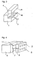
- a general embodiment of the invention is described therein by way of example about a rotation axis (14) rotatably arranged a first collimator block (1 a) and a second collimator block (1 b) with an interposed derotierenden element (12).
- the photoconductive fibers (3a, 3b) are guided in the respective collimator blocks, which are designed as micro-optical components.
- parallel beam bundles (13a, 13b) are generated. These are then imaged by means of the derotating element (12) on the other collimator block.
- FIG. 2 shows by way of example a monolithic collimator block (1). Integrated into these are the lenses (2) and - not shown here - the shots for the fibers (3). The fiber attachment, so the mechanical fixation by means of a terminal block (4) in the predetermined by the fiber recordings positions.
- Fig. 3 shows an opened collimator block (1) of Fig. 2 from the back.
- the fiber holder executed in two parts.
- a first V-shaped groove (18) which corresponds to a second groove (19) in the terminal block.
- the fiber (3) is held.
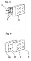
- FIG. 4 shows a modified embodiment of a micro-optical collimator system.
- a dowel or, for example, a suitable glass fiber is introduced into the opening from the grooves.
- FIG 5 shows an arrangement in which the fiber holders (9) with associated positioning elements are provided for exact positioning of the fibers (3).
- positioning elements may for example be micromotors, fiber aligners and others.
- FIG. 6 finally, an arrangement with a fiber array carrier (10) of Whysnutenplatten, which are started to each other sandwich, shown.
- the individual guide grooves (11) are preferably V-shaped or U-shaped.
Abstract
Claims (7)
- Transmetteur rotatif de signaux optiques comprenant un élément optique dérotatif et au moins deux pièces mobiles en rotation l'une par rapport à l'autre, des éléments conducteurs de faisceau ou formateurs de faisceau étant prévus sur chacune de ces pièces, les éléments conducteurs de faisceau ou formateurs de faisceau contenant chacun au moins un élément optique passif,
caractérisé par le fait
qu'au moins un élément optique passif est un réseau de lentilles d'un substrat sur lequel se trouvent plusieurs lentilles, qui a été produit par des procédés de fabrication microtechniques et qui est orienté avec précision par rapport à une structure composée d'un réseau de fibres, récepteurs ou émetteurs par une liaison géométrique ou à conjugaison de formes, au moyen d'une plaque à faces planes et parallèles servant d'entretoise. - Le dispositif selon la revendication 1,
caractérisé par le fait
qu'il existe au moins un élément actif supplémentaire et que l'élément actif comprend un émetteur ou un récepteur, comme par exemple une diode laser ou une photodiode. - Dispositif selon l'une des revendications précédentes,
caractérisé par le fait
qu'il est prévu un milieu photoactif dans lequel les propriétés de reproduction d'un réseau de lentilles se règlent par les éléments de couplage et de découplage sur la base de l'illumination. - Dispositif selon l'une des revendications précédentes,
caractérisé par le fait
que l'on utilise comme système dérotatif un élément optique actif qui produit la dérotation par la modification de ses propriétés optiques et qui n'a pas besoin d'être entraîné en rotation. - Dispositif selon l'une des revendications précédentes,
caractérisé par le fait
qu'il est prévu un milieu photoactif comme élément optique actif pour la dérotation. - Dispositif selon l'une des revendications précédentes,
caractérisé par le fait
qu'il est prévu un prisme de Dove acousto-optique comme élément optique actif pour la dérotation. - Dispositif selon l'une des revendications précédentes,
caractérisé par le fait
que l'on utilise comme système dérotatif un élément optique passif qui est inverseur et entraîné en rotation à demi-vitesse angulaire.
Applications Claiming Priority (3)
| Application Number | Priority Date | Filing Date | Title |
|---|---|---|---|
| DE10029206A DE10029206A1 (de) | 2000-06-20 | 2000-06-20 | Vorrichtung zur Übertragung optischer Signale |
| DE10029206 | 2000-06-20 | ||
| PCT/DE2001/002247 WO2001098801A2 (fr) | 2000-06-20 | 2001-06-18 | Dispositif de transmission de signaux optiques |
Publications (2)
| Publication Number | Publication Date |
|---|---|
| EP1297372A2 EP1297372A2 (fr) | 2003-04-02 |
| EP1297372B1 true EP1297372B1 (fr) | 2007-01-10 |
Family
ID=7645642
Family Applications (1)
| Application Number | Title | Priority Date | Filing Date |
|---|---|---|---|
| EP01951398A Expired - Lifetime EP1297372B1 (fr) | 2000-06-20 | 2001-06-18 | Dispositif de transmission de signaux optiques |
Country Status (6)
| Country | Link |
|---|---|
| US (1) | US7246949B2 (fr) |
| EP (1) | EP1297372B1 (fr) |
| JP (1) | JP2004501400A (fr) |
| AU (1) | AU2001272344A1 (fr) |
| DE (3) | DE10029206A1 (fr) |
| WO (1) | WO2001098801A2 (fr) |
Cited By (1)
| Publication number | Priority date | Publication date | Assignee | Title |
|---|---|---|---|---|
| DE102007061799A1 (de) * | 2007-12-19 | 2009-07-02 | Schleifring Und Apparatebau Gmbh | Linsenanordnung für optische Drehübertrager in beliebigen Umgebungsmedien |
Families Citing this family (29)
| Publication number | Priority date | Publication date | Assignee | Title |
|---|---|---|---|---|
| DE102004037684B4 (de) * | 2004-08-02 | 2006-09-21 | Schleifring Und Apparatebau Gmbh | Vorrichtungen zur optischen Drehübertragung mit freiem Innendurchmesser |
| US6782160B2 (en) | 2002-04-10 | 2004-08-24 | Lockheed Martin Corporation | Optical-signal coupler and related method |
| AU2002363820A1 (en) * | 2002-11-11 | 2004-06-03 | Cube Optics Ag | Support element for mounting optical elements and method for production of such a support element |
| DE10307419B4 (de) * | 2003-02-21 | 2005-11-10 | Siemens Ag | Optischer Drehübertrager |
| DE10344875A1 (de) * | 2003-09-26 | 2005-04-28 | Siemens Ag | Datenübertragungsverfahren und Optischer Drehübertrager mit Durchführung |
| CN100590469C (zh) * | 2005-04-04 | 2010-02-17 | 莫列斯公司 | 包括v形槽镜片阵列的多光纤mt型连接器和套管以及制造方法 |
| DE102006022023B4 (de) * | 2005-05-10 | 2011-07-21 | Schleifring und Apparatebau GmbH, 82256 | Mehrkanalige optische Drehkupplung |
| DE102005041547B3 (de) * | 2005-08-31 | 2007-02-15 | Schleifring Und Apparatebau Gmbh | Optischer Drehhübertrager |
| US7373041B2 (en) | 2005-08-31 | 2008-05-13 | Schleifring Und Apparatebau Gmbh | Optical rotary coupling |
| DE102005056899B4 (de) * | 2005-11-28 | 2007-10-18 | Schleifring Und Apparatebau Gmbh | Polarisationserhaltende optische Drehkupplung |
| DE102007013923B4 (de) | 2006-12-22 | 2012-02-02 | Schleifring Und Apparatebau Gmbh | Mehrkanaliger optischer Drehübertrager mit hoher Rückflußdämpfung |
| DE102007012224A1 (de) | 2007-03-12 | 2008-09-25 | Schleifring Und Apparatebau Gmbh | Mehrkanalige reflexionsarme optische Drehkupplung |
| DE102007029503A1 (de) | 2007-06-25 | 2009-01-02 | Schleifring Und Apparatebau Gmbh | Optischer Drehübertrager mit kurzer Baulänge |
| DE102007030258A1 (de) * | 2007-06-28 | 2009-01-02 | Schleifring Und Apparatebau Gmbh | Optischer Drehübertrager mit aktiver Bewegungskompensation |
| DE102008001653A1 (de) | 2008-05-08 | 2009-12-03 | Schleifring Und Apparatebau Gmbh | Linsenanordnung für optische Drehübertrager |
| DE102009026632A1 (de) | 2008-06-06 | 2009-12-10 | Schleifring Und Apparatebau Gmbh | Linsenanordnung mit Lagejustierung |
| EP2317756A1 (fr) | 2009-10-16 | 2011-05-04 | Axis AB | Caméra panoramique et inclinable |
| TW201135299A (en) * | 2010-04-14 | 2011-10-16 | Hon Hai Prec Ind Co Ltd | Optical couple connector and method for manufacturing same |
| US20110268387A1 (en) | 2010-04-28 | 2011-11-03 | Gregor Popp | Two Dimensional Fiber Collimator Array With High Return Loss |
| US9507093B2 (en) | 2010-04-28 | 2016-11-29 | Schleifring Und Apparatebau Gmbh | Polarization maintaining optical rotary joint |
| US8369662B2 (en) | 2010-11-19 | 2013-02-05 | Schleifring Und Apparatebau Gmbh | Fiber optic rotary joint with extended temperature range |
| WO2015035179A1 (fr) * | 2013-09-06 | 2015-03-12 | Mizushima Toshirou | Support d'embout |
| US10162127B2 (en) | 2013-10-15 | 2018-12-25 | Commscope, Inc. Of North Carolina | Expanded beam array for fiber optics |
| US9442293B2 (en) | 2014-05-06 | 2016-09-13 | Microsoft Technology Licensing, Llc | Composite variable light attenuator |
| JP6395219B2 (ja) | 2015-01-27 | 2018-09-26 | 日本電気株式会社 | ネットワークシステム |
| US20170052321A1 (en) | 2015-08-23 | 2017-02-23 | Commscope, Inc. Of North Carolina | Fused expanded beam connector |
| EP3182180B1 (fr) | 2015-12-17 | 2024-01-24 | Schleifring GmbH | Joint tournant à fibre optique multicanal ayant une métasurface achromatique |
| US10345804B2 (en) * | 2016-10-04 | 2019-07-09 | General Electric Company | Method and system for remote processing and analysis of industrial asset inspection data |
| CN112558245A (zh) * | 2020-12-30 | 2021-03-26 | 华进半导体封装先导技术研发中心有限公司 | 一种光耦合结构及其制备方法 |
Citations (2)
| Publication number | Priority date | Publication date | Assignee | Title |
|---|---|---|---|---|
| US4875750A (en) * | 1987-02-25 | 1989-10-24 | Siemens Aktiengesellschaft | Optoelectronic coupling element and method for its manufacture |
| JPH05333232A (ja) * | 1992-05-28 | 1993-12-17 | Tokyo Inst Of Technol | 無調整光コネクタ |
Family Cites Families (35)
| Publication number | Priority date | Publication date | Assignee | Title |
|---|---|---|---|---|
| JPS59105608A (ja) | 1912-08-01 | 1984-06-19 | スペリ−・コ−ポレイシヨン | 光フアイバ用回転接合装置 |
| US4027945A (en) | 1976-03-04 | 1977-06-07 | The United States Of America As Represented By The Secretary Of The Navy | Optical sliprings |
| US4258976A (en) * | 1978-11-06 | 1981-03-31 | The United States Of America As Represented By The Secretary Of The Navy | Derotation plate |
| NL7904279A (nl) * | 1979-05-31 | 1980-12-02 | Hollandse Signaalapparaten Bv | Draaibare lichtgeleiderkoppeling. |
| DE3207469C2 (de) * | 1981-03-02 | 1984-11-22 | Spinner GmbH Elektrotechnische Fabrik, 8000 München | Anordnung zur Übertragung von mehreren Lichtkanälen zwischen zwei ralativ zueinander um eine gemeinsame Drehachse rotierenden Bauteilen |
| DE3411121A1 (de) | 1984-03-26 | 1985-10-03 | Schleifring und Apparatebau GmbH, 8080 Fürstenfeldbruck | Vorrichtung zur uebertragung von lichtsignalen zwischen zwei bauteilen |
| US4772093A (en) * | 1985-12-12 | 1988-09-20 | Microvasive, Inc. | Fiber-optic image-carrying device |
| US4943137A (en) * | 1987-01-27 | 1990-07-24 | Kdi Electro-Tec Corporation | Multi-channel, off-axis, bi-directional fiber optic slipring |
| JPS646916A (en) * | 1987-06-29 | 1989-01-11 | Hoya Corp | Optical switch and its manufacture |
| US4872737A (en) * | 1988-09-07 | 1989-10-10 | Hitachi Cable Limited | Multi-port fiberoptic rotary joint |
| JPH0281506U (fr) * | 1988-12-14 | 1990-06-22 | ||
| JP2780487B2 (ja) | 1990-11-30 | 1998-07-30 | 日立電線株式会社 | 多心光ロータリージョイント |
| JP2687723B2 (ja) | 1990-11-30 | 1997-12-08 | 日立電線株式会社 | 多芯光ロータリージョイント |
| DE69126845D1 (de) | 1990-11-28 | 1997-08-21 | Hitachi Cable | Faseroptische Drehkupplung mit Mehrfachzugang |
| DE4101043C3 (de) * | 1991-01-16 | 1995-10-12 | Ant Nachrichtentech | Optischer Schalter |
| US5157745A (en) * | 1991-09-16 | 1992-10-20 | The United States Of America As Represented By The Secretary Of The Navy | Multi-channel fiber optic rotary joint for single-mode fiber |
| JPH0572444A (ja) * | 1991-09-17 | 1993-03-26 | Fujitsu Ltd | 多心光コネクタ |
| US5211535A (en) * | 1991-12-30 | 1993-05-18 | General Electric Company | Labyrinth seals for gas turbine engine |
| US5311535A (en) | 1992-07-28 | 1994-05-10 | Karpinski Arthur A | Monolithic laser diode array providing emission from a minor surface thereof |
| US5257332A (en) | 1992-09-04 | 1993-10-26 | At&T Bell Laboratories | Optical fiber expanded beam coupler |
| JP3304174B2 (ja) | 1993-10-07 | 2002-07-22 | 株式会社日立製作所 | 薄板の洗浄方法 |
| US5371814A (en) * | 1993-11-08 | 1994-12-06 | The United States Of America As Represented By The Secretary Of The Navy | Passive, multi-channel fiber optic rotary joint assembly |
| JPH07311320A (ja) * | 1994-05-16 | 1995-11-28 | Hitachi Cable Ltd | 多チャンネル光モジュール |
| US5442721A (en) | 1994-08-08 | 1995-08-15 | The United States Of America As Represented By The Secretary Of The Navy | Fiber-optic rotary joint with bundle collimator assemblies |
| JP3323662B2 (ja) * | 1994-09-01 | 2002-09-09 | 株式会社リコー | 光送受信モジュールの製造方法及び光送受信モジュール |
| US5535294A (en) | 1995-05-08 | 1996-07-09 | Ceram Optec Industries, Inc. | Connector for multichannel transmission of optical signals through rotating interface |
| US5621830A (en) | 1995-06-07 | 1997-04-15 | Smith & Nephew Dyonics Inc. | Rotatable fiber optic joint |
| JP3569576B2 (ja) * | 1995-09-04 | 2004-09-22 | 旭栄研磨加工株式会社 | 光ファイバー実装モジュールの製造方法 |
| JPH09178987A (ja) * | 1995-12-25 | 1997-07-11 | Kiyokuei Kenma Kako Kk | 半導体レーザー素子の取付け方法およびその実装基板 |
| US5940562A (en) * | 1996-03-12 | 1999-08-17 | Minnesota Mining And Manufacturing Company | Stubless optoelectronic device receptacle |
| JPH1062605A (ja) * | 1996-08-20 | 1998-03-06 | Mitsubishi Electric Corp | アレイレンズ |
| US5872879A (en) * | 1996-11-25 | 1999-02-16 | Boston Scientific Corporation | Rotatable connecting optical fibers |
| US5996376A (en) * | 1997-04-11 | 1999-12-07 | Digital Optics Corporation | Methods of forming optical rods including three-dimensional patterns on end faces thereof |
| US5905824A (en) * | 1997-12-09 | 1999-05-18 | Delisle; Vincent | Temperature compensated insensitive optical multiplexor/demultiplexor |
| US6445939B1 (en) * | 1999-08-09 | 2002-09-03 | Lightlab Imaging, Llc | Ultra-small optical probes, imaging optics, and methods for using same |
-
2000
- 2000-06-20 DE DE10029206A patent/DE10029206A1/de not_active Withdrawn
-
2001
- 2001-06-18 US US10/311,860 patent/US7246949B2/en not_active Expired - Lifetime
- 2001-06-18 EP EP01951398A patent/EP1297372B1/fr not_active Expired - Lifetime
- 2001-06-18 JP JP2002504509A patent/JP2004501400A/ja active Pending
- 2001-06-18 WO PCT/DE2001/002247 patent/WO2001098801A2/fr active IP Right Grant
- 2001-06-18 DE DE50111857T patent/DE50111857D1/de not_active Expired - Lifetime
- 2001-06-18 AU AU2001272344A patent/AU2001272344A1/en not_active Abandoned
- 2001-06-18 DE DE10192555T patent/DE10192555D2/de not_active Expired - Fee Related
Patent Citations (2)
| Publication number | Priority date | Publication date | Assignee | Title |
|---|---|---|---|---|
| US4875750A (en) * | 1987-02-25 | 1989-10-24 | Siemens Aktiengesellschaft | Optoelectronic coupling element and method for its manufacture |
| JPH05333232A (ja) * | 1992-05-28 | 1993-12-17 | Tokyo Inst Of Technol | 無調整光コネクタ |
Non-Patent Citations (1)
| Title |
|---|
| MILSTER T.D.: "Handbook of Optics Vol. II", 1995, MCGRAW-HILL, NEW YORK * |
Cited By (1)
| Publication number | Priority date | Publication date | Assignee | Title |
|---|---|---|---|---|
| DE102007061799A1 (de) * | 2007-12-19 | 2009-07-02 | Schleifring Und Apparatebau Gmbh | Linsenanordnung für optische Drehübertrager in beliebigen Umgebungsmedien |
Also Published As
| Publication number | Publication date |
|---|---|
| US20040017984A1 (en) | 2004-01-29 |
| DE10192555D2 (de) | 2003-09-11 |
| DE50111857D1 (de) | 2007-02-22 |
| DE10029206A1 (de) | 2002-01-10 |
| WO2001098801A3 (fr) | 2002-06-06 |
| WO2001098801A2 (fr) | 2001-12-27 |
| AU2001272344A1 (en) | 2002-01-02 |
| US7246949B2 (en) | 2007-07-24 |
| JP2004501400A (ja) | 2004-01-15 |
| EP1297372A2 (fr) | 2003-04-02 |
Similar Documents
| Publication | Publication Date | Title |
|---|---|---|
| EP1297372B1 (fr) | Dispositif de transmission de signaux optiques | |
| DE3103010C2 (fr) | ||
| EP1316165B1 (fr) | Modificateur optique et son procede de production | |
| DE19610881B4 (de) | Mikrosystembaustein | |
| DE102010031674B4 (de) | Kopplungseinheit für Lichtwellenleiter | |
| WO2019037810A1 (fr) | Dispositif d'émission comprenant un miroir de balayage recouvert par un élément de recouvrement de collimation | |
| DE102005056899B4 (de) | Polarisationserhaltende optische Drehkupplung | |
| DE102006022023B4 (de) | Mehrkanalige optische Drehkupplung | |
| EP2171523B1 (fr) | Dispositif pour regrouper des rayons lumineux individuels de différentes longueurs d'onde en un faisceau lumineux coaxial | |
| EP2162772A1 (fr) | Dispositif rotatif de transmission optique doté d'une compensation active du déplacement | |
| DE102007012224A1 (de) | Mehrkanalige reflexionsarme optische Drehkupplung | |
| EP2106561B1 (fr) | Joint optique tournant multicanaux a affaiblissement marque de pertes par reflexion | |
| DE10201127A1 (de) | Anordnung zum Ein- und/oder Auskoppeln optischer Signale mindestens eines optischen Datenkanals in bzw. aus einem Lichtwellenleiter | |
| DE2900895A1 (de) | Faseroptische leitungskupplung | |
| DE19720619A1 (de) | Verfahren und Vorrichtung zum Multiplexen von übertragenen Lichtsignalen | |
| DE19706053B4 (de) | Schaltanordnung zum Schalten und Einkoppeln eines Lichtbündels in mindestens eine Ausgangsfaser | |
| DE102016116410B4 (de) | Optisches system zur einkopplung von laserlicht in eine lichtleitfaser, insbesondere eine einmoden-faser und ein verfahren zur erhöhung einer einstellgenauigkeit eines fokus eines lichtstrahls | |
| DE3330901C2 (fr) | ||
| EP3961279A1 (fr) | Fiche à fibre optique et procédé d'ajustement | |
| DE10320991B4 (de) | Optische Positionsmesseinrichtung | |
| EP1666944B1 (fr) | Coupleur à fibre optique | |
| DE3606682C1 (en) | Optical fibre arrangement for microoptical grating multiplexers and demultiplexers | |
| WO1988001065A1 (fr) | Dispositif d'alignement lateral d'images optiques | |
| EP1315992A2 (fr) | Dispositif de couplage et son procede de fabrication | |
| DE102005041547B3 (de) | Optischer Drehhübertrager |
Legal Events
| Date | Code | Title | Description |
|---|---|---|---|
| PUAI | Public reference made under article 153(3) epc to a published international application that has entered the european phase |
Free format text: ORIGINAL CODE: 0009012 |
|
| 17P | Request for examination filed |
Effective date: 20030120 |
|
| AK | Designated contracting states |
Kind code of ref document: A2 Designated state(s): AT BE CH CY DE DK ES FI FR GB GR IE IT LI LU MC NL PT SE TR |
|
| AX | Request for extension of the european patent |
Extension state: AL LT LV MK RO SI |
|
| RIN1 | Information on inventor provided before grant (corrected) |
Inventor name: THIELE, HANS Inventor name: POISEL, HANS |
|
| 17Q | First examination report despatched |
Effective date: 20031028 |
|
| GRAP | Despatch of communication of intention to grant a patent |
Free format text: ORIGINAL CODE: EPIDOSNIGR1 |
|
| GRAS | Grant fee paid |
Free format text: ORIGINAL CODE: EPIDOSNIGR3 |
|
| GRAA | (expected) grant |
Free format text: ORIGINAL CODE: 0009210 |
|
| AK | Designated contracting states |
Kind code of ref document: B1 Designated state(s): AT BE CH CY DE DK ES FI FR GB GR IE IT LI LU MC NL PT SE TR |
|
| PG25 | Lapsed in a contracting state [announced via postgrant information from national office to epo] |
Ref country code: FI Free format text: LAPSE BECAUSE OF FAILURE TO SUBMIT A TRANSLATION OF THE DESCRIPTION OR TO PAY THE FEE WITHIN THE PRESCRIBED TIME-LIMIT Effective date: 20070110 Ref country code: IE Free format text: LAPSE BECAUSE OF FAILURE TO SUBMIT A TRANSLATION OF THE DESCRIPTION OR TO PAY THE FEE WITHIN THE PRESCRIBED TIME-LIMIT Effective date: 20070110 Ref country code: DK Free format text: LAPSE BECAUSE OF FAILURE TO SUBMIT A TRANSLATION OF THE DESCRIPTION OR TO PAY THE FEE WITHIN THE PRESCRIBED TIME-LIMIT Effective date: 20070110 Ref country code: NL Free format text: LAPSE BECAUSE OF FAILURE TO SUBMIT A TRANSLATION OF THE DESCRIPTION OR TO PAY THE FEE WITHIN THE PRESCRIBED TIME-LIMIT Effective date: 20070110 |
|
| REG | Reference to a national code |
Ref country code: GB Ref legal event code: FG4D Free format text: NOT ENGLISH |
|
| REG | Reference to a national code |
Ref country code: IE Ref legal event code: FG4D Free format text: LANGUAGE OF EP DOCUMENT: GERMAN |
|
| REF | Corresponds to: |
Ref document number: 50111857 Country of ref document: DE Date of ref document: 20070222 Kind code of ref document: P |
|
| PG25 | Lapsed in a contracting state [announced via postgrant information from national office to epo] |
Ref country code: SE Free format text: LAPSE BECAUSE OF FAILURE TO SUBMIT A TRANSLATION OF THE DESCRIPTION OR TO PAY THE FEE WITHIN THE PRESCRIBED TIME-LIMIT Effective date: 20070410 |
|
| PG25 | Lapsed in a contracting state [announced via postgrant information from national office to epo] |
Ref country code: ES Free format text: LAPSE BECAUSE OF FAILURE TO SUBMIT A TRANSLATION OF THE DESCRIPTION OR TO PAY THE FEE WITHIN THE PRESCRIBED TIME-LIMIT Effective date: 20070421 |
|
| GBT | Gb: translation of ep patent filed (gb section 77(6)(a)/1977) |
Effective date: 20070412 |
|
| PG25 | Lapsed in a contracting state [announced via postgrant information from national office to epo] |
Ref country code: PT Free format text: LAPSE BECAUSE OF FAILURE TO SUBMIT A TRANSLATION OF THE DESCRIPTION OR TO PAY THE FEE WITHIN THE PRESCRIBED TIME-LIMIT Effective date: 20070611 |
|
| NLV1 | Nl: lapsed or annulled due to failure to fulfill the requirements of art. 29p and 29m of the patents act | ||
| ET | Fr: translation filed | ||
| REG | Reference to a national code |
Ref country code: IE Ref legal event code: FD4D |
|
| PLBE | No opposition filed within time limit |
Free format text: ORIGINAL CODE: 0009261 |
|
| STAA | Information on the status of an ep patent application or granted ep patent |
Free format text: STATUS: NO OPPOSITION FILED WITHIN TIME LIMIT |
|
| 26N | No opposition filed |
Effective date: 20071011 |
|
| BERE | Be: lapsed |
Owner name: SCHLEIFRING UND APPARATEBAU G.M.B.H. Effective date: 20070630 |
|
| PG25 | Lapsed in a contracting state [announced via postgrant information from national office to epo] |
Ref country code: MC Free format text: LAPSE BECAUSE OF NON-PAYMENT OF DUE FEES Effective date: 20070630 |
|
| REG | Reference to a national code |
Ref country code: CH Ref legal event code: PL |
|
| PG25 | Lapsed in a contracting state [announced via postgrant information from national office to epo] |
Ref country code: BE Free format text: LAPSE BECAUSE OF NON-PAYMENT OF DUE FEES Effective date: 20070630 |
|
| PG25 | Lapsed in a contracting state [announced via postgrant information from national office to epo] |
Ref country code: IT Free format text: LAPSE BECAUSE OF FAILURE TO SUBMIT A TRANSLATION OF THE DESCRIPTION OR TO PAY THE FEE WITHIN THE PRESCRIBED TIME-LIMIT Effective date: 20070110 Ref country code: CH Free format text: LAPSE BECAUSE OF NON-PAYMENT OF DUE FEES Effective date: 20070630 Ref country code: GR Free format text: LAPSE BECAUSE OF FAILURE TO SUBMIT A TRANSLATION OF THE DESCRIPTION OR TO PAY THE FEE WITHIN THE PRESCRIBED TIME-LIMIT Effective date: 20070411 Ref country code: LI Free format text: LAPSE BECAUSE OF NON-PAYMENT OF DUE FEES Effective date: 20070630 |
|
| PG25 | Lapsed in a contracting state [announced via postgrant information from national office to epo] |
Ref country code: AT Free format text: LAPSE BECAUSE OF NON-PAYMENT OF DUE FEES Effective date: 20070618 |
|
| PG25 | Lapsed in a contracting state [announced via postgrant information from national office to epo] |
Ref country code: CY Free format text: LAPSE BECAUSE OF FAILURE TO SUBMIT A TRANSLATION OF THE DESCRIPTION OR TO PAY THE FEE WITHIN THE PRESCRIBED TIME-LIMIT Effective date: 20070110 |
|
| PG25 | Lapsed in a contracting state [announced via postgrant information from national office to epo] |
Ref country code: LU Free format text: LAPSE BECAUSE OF NON-PAYMENT OF DUE FEES Effective date: 20070618 |
|
| PG25 | Lapsed in a contracting state [announced via postgrant information from national office to epo] |
Ref country code: TR Free format text: LAPSE BECAUSE OF FAILURE TO SUBMIT A TRANSLATION OF THE DESCRIPTION OR TO PAY THE FEE WITHIN THE PRESCRIBED TIME-LIMIT Effective date: 20070110 |
|
| REG | Reference to a national code |
Ref country code: FR Ref legal event code: PLFP Year of fee payment: 16 |
|
| REG | Reference to a national code |
Ref country code: FR Ref legal event code: PLFP Year of fee payment: 17 |
|
| REG | Reference to a national code |
Ref country code: FR Ref legal event code: PLFP Year of fee payment: 18 |
|
| PGFP | Annual fee paid to national office [announced via postgrant information from national office to epo] |
Ref country code: DE Payment date: 20200626 Year of fee payment: 20 Ref country code: FR Payment date: 20200623 Year of fee payment: 20 |
|
| PGFP | Annual fee paid to national office [announced via postgrant information from national office to epo] |
Ref country code: GB Payment date: 20200625 Year of fee payment: 20 |
|
| REG | Reference to a national code |
Ref country code: DE Ref legal event code: R071 Ref document number: 50111857 Country of ref document: DE |
|
| REG | Reference to a national code |
Ref country code: GB Ref legal event code: PE20 Expiry date: 20210617 |
|
| PG25 | Lapsed in a contracting state [announced via postgrant information from national office to epo] |
Ref country code: GB Free format text: LAPSE BECAUSE OF EXPIRATION OF PROTECTION Effective date: 20210617 |