EP1297372B1 - Device for transmitting optical signals - Google Patents
Device for transmitting optical signals Download PDFInfo
- Publication number
- EP1297372B1 EP1297372B1 EP01951398A EP01951398A EP1297372B1 EP 1297372 B1 EP1297372 B1 EP 1297372B1 EP 01951398 A EP01951398 A EP 01951398A EP 01951398 A EP01951398 A EP 01951398A EP 1297372 B1 EP1297372 B1 EP 1297372B1
- Authority
- EP
- European Patent Office
- Prior art keywords
- optical
- optical element
- der
- die
- active
- Prior art date
- Legal status (The legal status is an assumption and is not a legal conclusion. Google has not performed a legal analysis and makes no representation as to the accuracy of the status listed.)
- Expired - Lifetime
Links
Images


Classifications
-
- G—PHYSICS
- G02—OPTICS
- G02B—OPTICAL ELEMENTS, SYSTEMS OR APPARATUS
- G02B6/00—Light guides; Structural details of arrangements comprising light guides and other optical elements, e.g. couplings
- G02B6/24—Coupling light guides
- G02B6/26—Optical coupling means
- G02B6/32—Optical coupling means having lens focusing means positioned between opposed fibre ends
-
- G—PHYSICS
- G02—OPTICS
- G02B—OPTICAL ELEMENTS, SYSTEMS OR APPARATUS
- G02B6/00—Light guides; Structural details of arrangements comprising light guides and other optical elements, e.g. couplings
- G02B6/24—Coupling light guides
- G02B6/36—Mechanical coupling means
- G02B6/3604—Rotary joints allowing relative rotational movement between opposing fibre or fibre bundle ends
-
- G—PHYSICS
- G02—OPTICS
- G02B—OPTICAL ELEMENTS, SYSTEMS OR APPARATUS
- G02B6/00—Light guides; Structural details of arrangements comprising light guides and other optical elements, e.g. couplings
- G02B6/24—Coupling light guides
- G02B6/36—Mechanical coupling means
- G02B6/3628—Mechanical coupling means for mounting fibres to supporting carriers
- G02B6/3632—Mechanical coupling means for mounting fibres to supporting carriers characterised by the cross-sectional shape of the mechanical coupling means
- G02B6/3636—Mechanical coupling means for mounting fibres to supporting carriers characterised by the cross-sectional shape of the mechanical coupling means the mechanical coupling means being grooves
-
- G—PHYSICS
- G02—OPTICS
- G02B—OPTICAL ELEMENTS, SYSTEMS OR APPARATUS
- G02B6/00—Light guides; Structural details of arrangements comprising light guides and other optical elements, e.g. couplings
- G02B6/24—Coupling light guides
- G02B6/36—Mechanical coupling means
- G02B6/3628—Mechanical coupling means for mounting fibres to supporting carriers
- G02B6/3664—2D cross sectional arrangements of the fibres
- G02B6/3676—Stacked arrangement
Definitions
- the invention relates to a device for transmitting optical signals, in particular via interfaces between rotationally movable parts.
- Such cable drums are used, for example, in Remotely Operated Vehicles (ROV) for land and water (bomb deterrence drone, diving robot in the offshore industry) or sonar "to-wed
- ROV Remotely Operated Vehicles
- Further applications for multichannel transformers are, for example, rotatable remote sensing instruments for civil, scientific and military applications that generate high data streams (radar, IR / visual ect.), such as camera heads below Helicopters, unmanned aerial vehicles (UAV), large telescopes, satellites.
- optics used for coupling or decoupling have a decisive influence on the quality of the transmission systems described here.
- Various prior art designs of these optics, particularly for use with the third derating element transfer technology, are discussed below.
- the considerations are made by way of example for glass fibers, but they are analogously applicable to other forms of optical fibers such as plastic optical fibers or for active components such as transmitters or receivers.
- U.S. Patent No. 4,725,116 discloses a modular multi-channel transmission system. There each channel is transmitted by means of its own mirror. The mechanical complexity of this system is considerable, since each mirror requires its own optics and correspondingly accurate storage. In addition, the length of the beam paths increases with increasing number of channels, which in turn means a deterioration of the optical properties. In addition, at those points where the supply fibers pass the beam path, attenuation peaks occur. Furthermore, length and weight increase proportionally with the number of channels. As a result, the unit grows even at low channel count to a size that is unacceptable for many applications.
- US Pat. No. 4,872,737 describes a multi-channel transformer based on a Dove prism.
- the beam input or output takes place by means of several individual collimators. These collimators must be adjusted individually.
- a relatively long mechanical lever or a fine thread is necessary, which also takes up additional space.
- the area to be imaged increases, that is to say the entire area that is imaged via the derotating system.
- a larger optical system is necessary, which in turn has a higher optical attenuation through the longer paths and at the same time makes higher demands on the adjustment accuracy. Therefore, in such a solution, for example, the enlargement of a mechanical lever to increase the adjustment accuracy brings no improvement.
- US Pat. No. 5,442,721 incorporates a bundle of conventional collimators as a whole into the transformer. As a result, only a single adjustment of the entire Kollimatorbündels is necessary.
- a major disadvantage of this bundling is that the not inconsiderable tolerances of the individual collimators can not be compensated.
- the individual collimators themselves consist of fiber holders and lens systems, which are firmly connected in a ferrule. The mounting accuracy of these collimators is limited and usually does not meet the requirements of a rotation transmission system. This is one such approach, in which no individual adjustment der.Kollimatoren is possible especially for a singlemode transmission system can not be used.
- the invention has for its object to provide an optical transmission system for rotating movements, which no longer has the disadvantages mentioned above and in particular with high numbers of channels in high transmission quality can be realized inexpensively.
- the device according to the invention combines high precision and thus high transmission quality with simple adjustment.
- micro-optical component is a multifunctional component, in which the different sub-functions are produced with just such a uniform process. Examples of the integration of several functions are z.
- lens arrays with many lenses or combinations of lenses and mechanical fiber mounts are, for example, league, laserwriting, etc. They are often borrowed from semiconductor technology or microsystems technology or related to these processes. This makes it possible to produce several subcomponents or functional parts in a process with the highest accuracy.
- micro-optical system is based in particular on the recognition that on the one hand the addition of tolerances can be prevented only by a uniform overall process and on the other hand shortened by reducing the surface to be imaged the optical paths and thus the sensitivity to tolerances can be reduced.
- the optical components are manufactured one at a time using conventional optical manufacturing processes, such as grinding and polishing individual lenses.
- the lenses thus produced are then combined, for example, together with the glass fibers in a ferrule to form a collimator.
- the tolerances of all process steps add up. These are, for example, contour errors and dimensional tolerances of the lenses, positional errors of the lenses in the collimators, positional tolerances of the glass fiber with respect to the lens, tolerances of the ferrule, positional tolerances of the ferrule in the transformer.
- the passive optical element consists of a lens array.
- This lens array may have a one-dimensional, preferably linear arrangement. Very advantageous because space-saving are two-dimensional arrangements of the lenses. These can be arranged, for example, round or in a square matrix or laterally offset from one another. Also, three-dimensional arrangements are advantageously feasible here.
- passive optical elements such as guides of optical waveguides, in particular light-guiding fibers can be provided. These can also be formed in one, two or three dimensions.
- beam-guiding and beam-shaping optical elements are integrated in a first structure.
- the elements which are coupled in and out are integrated in a second structure, wherein both structures are precisely aligned with one another via a positive engagement.
- a lens array with high-precision pitch (distance between the lenses) is fixedly mounted on an array of fibers, receivers or transmitters, the alignment being either via a positive engagement, i. via a plane-parallel plate as a spacer (the thickness of the lens carrier can be matched to their focal length) and guide fiber grooves for positioning or otherwise executed positive engagement (see US Patent: US 5,446,815).
- optical components described here can also be easily used for signal transmission between stationary components, such as in plugs.
- Another advantageous embodiment of the invention has integrated active optical elements. These may be, for example, light emitting diodes, laser diodes or photodiodes.
- the active or passive elements are also made of one piece.
- Another advantageous embodiment of the invention comprises jet-guiding or beam-forming elements, such as lenses, which are manufactured together with guides of the on or out coupling components.
- beam-guiding and beam-shaping optical elements are integrated in a first structure.
- the coupling elements are integrated in a second structure, wherein both structures are continuously adjustable against each other.
- This adjustment can be done for example by a micromechanical actuator which, for example, the arrays against each other or even a macro-mechanical actuator such as a piezoceramic element.
- beam-guiding and beam-shaping optical elements are integrated in a first structure.
- the coupling and uncoupling elements are integrated in a second structure, wherein a structure is adapted in the manufacture of the other.
- one of the structures is first made, and then the second is made to match them so that the tolerances are minimal.
- the jet-guiding or jet-forming a photoactive medium is designed such that adjust the imaging properties of the lenses due to the irradiation by the coupling-in or out accordingly.
- a derotating system is provided when at least one channel is to be transmitted off-axis.
- An advantageous developments of the invention is that an active optical element is used as a derotating system.
- This element is designed such that the derotation is generated by changing its optical properties and thus does not have to be moved mechanically with the rotation.
- Such a further development of the invention has the advantage that space and weight can be saved once again by eliminating additional storage and transmission components, possibly even adjustment problems can be eliminated by the adaptability of the optical element.
- a photoactive medium is used as an active optical element for derotation.
- the derotation is controlled by the incident light.
- the imaging properties are self-adjusting according to the radiation from the coupling and uncoupling elements. The "accuracy" is achieved here rather by a self-adaptive system that is also insensitive to misalignment.
- the derotating system is realized in the form of a photoactive crystal, whose optical properties by the irradiation with the be changed over-carrying optical signals.
- This technology would also allow beam forming, directional shaping and optical derotation to be realized with a single optical element between the input and output components.
- an acousto-optical as an active optical element for derotation Dove prism used.
- the imaging properties of an inverting element such as a dove prism are replaced by two acousto-optic beam deflectors and a cylindrical concave mirror in between. This element then stands still, the rotation of the light rays is generated by applying periodically fluctuating voltages.
- AODP Acousto-optic Dove Prism
- Another embodiment of the invention provides as derotierendes system a passive optical element. This element makes the derotation means of its optical mapping function and therefore need not be rotated with the main motion.
- a passive optical element which is inverting. Therefore, this element must be rotated at half the angular speed of the main rotation.
- the inverting optical element of the derating system in one of the known designs such as Dove prism, Inverting fiber bundle, etc.
- the inverting optical element of the derating system can be "actively adjusted” for high attenuation variations, both once with subsequent fixation as well as continuously during operation. This can be done via sensitive control elements such.
- B. piezoelectric actuators which in the case of continuous Adjustment be readjusted via a control loop.
- an inverting optical element eg the Dove prism, the angular accuracy of the refractive edges, or the Schmidt-Pechan prism inaccuracies by the cementing of two components
- adjustment screws not easily achievable adjustment of the optical axis of the inverting element to the rotation axis Tumbling of the focus point can occur - even with ideally aligned to the axis of rotation fiber-lens arrays - would occur for some applications unacceptable damping variations.
- a more stable signal over the rotation could also be achieved by means of an actively mounted inverting optical element.
- the element In addition to the mechanical coarse adjustment, the element would be supported on both sides (rotor and stator side) with at least one piezoelectric actuator and an associated counter bearing in order to be able to sensitively adjust the optical axis of the prism in such a way that it coincides with the mechanical axis of rotation of the element. of the rotating fiber-lens array matches.
- the piezo actuator has the advantage that it allows much more sensitive movements than manual adjustment screws.
- the actual optical axis of the prism could be aligned once on the axis of rotation and fixed so.
- the adjustment can be continuous also adaptively controlled during the rotation, so that then effects such as bearing clearance, gear play or tiny Restdejustagen the fiber lens arrays can be corrected.
- the piezo actuators are then controlled via a control loop so that the fibers in the array are always hit by the focus points of the lenses.
- This variant has over the Einzelfaserjustage the advantage that only a few control elements are needed that they can build larger and that for the purpose of the control loop only one channel must be queried and not every single.
- a separate channel over which no further information is transmitted can only be used for regulatory purposes.
- the inverting optical element of the derating system can be somewhat shortened in design or, as far as large-scale production is concerned, simplified by replacing the refractive surfaces of a prism or a lens by Fresnel structures or diffractive structures.
- An illustration of such a system has been published in "A New Type of Lens with Binary Subwavelength Structures" Optics and Photonics News, December 1997.
- a general embodiment of the invention is described therein by way of example about a rotation axis (14) rotatably arranged a first collimator block (1 a) and a second collimator block (1 b) with an interposed derotierenden element (12).
- the photoconductive fibers (3a, 3b) are guided in the respective collimator blocks, which are designed as micro-optical components.
- parallel beam bundles (13a, 13b) are generated. These are then imaged by means of the derotating element (12) on the other collimator block.
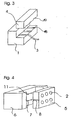
- FIG. 2 shows by way of example a monolithic collimator block (1). Integrated into these are the lenses (2) and - not shown here - the shots for the fibers (3). The fiber attachment, so the mechanical fixation by means of a terminal block (4) in the predetermined by the fiber recordings positions.
- Fig. 3 shows an opened collimator block (1) of Fig. 2 from the back.
- the fiber holder executed in two parts.
- a first V-shaped groove (18) which corresponds to a second groove (19) in the terminal block.
- the fiber (3) is held.
- FIG. 4 shows a modified embodiment of a micro-optical collimator system.
- a dowel or, for example, a suitable glass fiber is introduced into the opening from the grooves.
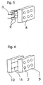
- FIG 5 shows an arrangement in which the fiber holders (9) with associated positioning elements are provided for exact positioning of the fibers (3).
- positioning elements may for example be micromotors, fiber aligners and others.
- FIG. 6 finally, an arrangement with a fiber array carrier (10) of Whysnutenplatten, which are started to each other sandwich, shown.
- the individual guide grooves (11) are preferably V-shaped or U-shaped.
Landscapes
- Physics & Mathematics (AREA)
- General Physics & Mathematics (AREA)
- Optics & Photonics (AREA)
- Optical Couplings Of Light Guides (AREA)
- Measurement Of The Respiration, Hearing Ability, Form, And Blood Characteristics Of Living Organisms (AREA)
- Optical Elements Other Than Lenses (AREA)
- Mechanical Coupling Of Light Guides (AREA)
Abstract
Description
Die Erfindung betrifft eine Vorrichtung zur Übertragung optischer Signale, insbesondere über Schnittstellen zwischen rotatorisch bewegbaren Teilen.The invention relates to a device for transmitting optical signals, in particular via interfaces between rotationally movable parts.
In vielen Applikationen Optischer Datenübertragungen mit Lichtwellenleitern ist auch eine Übertragung über drehende Schnittstellen notwendig. Hierzu sind dem Stand der Technik entsprechend verschiedene Einkanal-Übertragungssysteme bekannt. Mit steigenden Datenraten nimmt auch die Anzahl der zu übertragenden Kanäle zu. Somit nehmen die Einsatzgebiete für mehrkanalige Übertragungssysteme stark zu.
Beispielsweise ist beim Einsatz von Kabeltrommeln mit Lichtwellenleitern im Kabel, bei denen beim Ausbringen oder Einholen des Kabels Datenübertragung über die Lichtwellenleiter stattfinden muss, ein optischer Mehrkanalübertrager notwendig. Derartige Kabeltrommeln werden beispielsweise in Remotely Operated Vehicles (ROV) für Land und Wasser (Bombenentschärfungsdrohne, Tauchroboter in der Offshoreindustrie) bzw. Sonar "to-wed arrays", welche hinter Schiffen hergezogen werden um den Meeresboden zu vermessen, eingesetzt. Weitere Einsatzgebiete für Mehrkanalübertrager sind beispielsweise drehbare Fernerkundungsinstrumente für zivile, wissenschaftliche und militärische Applikationen, die hohe Datenströme erzeugen (Radar, IR/visuell ect.), wie z.B. Kameraköpfe unter Hubschraubern, unbemannten Flugkörpern (UAV-unmanned aerial vehicle), Großteleskope, Satelliten.In many applications of optical data transmission with fiber optic cables, transmission over rotating interfaces is also necessary. For this purpose, according to the prior art, various single-channel transmission systems are known. With increasing data rates, the number of channels to be transmitted also increases. Thus, the areas of application for multi-channel transmission systems are increasing rapidly.
For example, when using cable drums with optical fibers in the cable, in which data transmission over the optical fibers must take place when deploying or retrieving the cable, an optical multi-channel transformer is necessary. Such cable drums are used, for example, in Remotely Operated Vehicles (ROV) for land and water (bomb deterrence drone, diving robot in the offshore industry) or sonar "to-wed Further applications for multichannel transformers are, for example, rotatable remote sensing instruments for civil, scientific and military applications that generate high data streams (radar, IR / visual ect.), such as camera heads below Helicopters, unmanned aerial vehicles (UAV), large telescopes, satellites.
Für den Einsatz auf Schiffen und Flugzeugen ist ein robustes Design notwendig (shock and vibration), speziell was die Justagestandfestigkeit betrifft (was bei wenigen kleinen Komponenten offensichtlich besser zu realisieren ist als bei vielen großen). Im Fall von Flugzeugen, im Speziellen Flugdrohnen, sind geringes Gewicht und kleine Abmessungen ein zusätzliches entscheidendes Kriterium das von den bisher bekannten Lösungen kaum erreicht wird.For use on ships and aircraft, a robust design is necessary (shock and vibration), especially with regard to the adjustment stability (which is obviously easier to achieve with a few small components than with many large ones). In the case of aircraft, in particular aircraft drones, light weight and small dimensions are an additional decisive criterion which is hardly achieved by the previously known solutions.
Zur mehrkanaligen Drehübertragung sind zahlreiche Lösungsansätze bekannt. Eine gute Übersicht gibt der Aufsatz von Speer und Koch :"The diversity of fiberoptic rotary connectors", SPIE Vol 839, S. 122-129.
Grundsätzlich lassen sich die Lösungsansätze folgendermaßen einteilen:
- Konzentrische Faserbündel, bei denen das Licht des jeweils zu übertragenden Kanals auf konzentrische, (hohl-)zylindrische Lichtwellenleiteranordnungen verteilt wird, die an der Schnittstelle gegeneinander verdreht werden können.
Eine solche Anordnung ist in der US-Patentschrift 4,027,945 beschrieben.
Der wesentliche Nachteil dieser Anordnung ist, daß die Lichtleiter um so größere Durchmesser benötigen, je weiter außen der jeweilige Kanal liegt. Dieses System ist beispielsweise mit Plastik-Lichtleitern sehr gut realisierbar. Eine Übertragung mit Singlemode-Fasern ist praktisch ausgeschlossen, da diese aufgrund ihres äußerst geringen Kerndurchmessers kaum in ausreichender Anzahl mit ausreichender Genauigkeit montiert werden können. Mit steigendem Faserdurchmesser nimmt auch die Dispersion zu und damit die übertragbare Bandbreite bzw. Datenrate ab. Somit entspricht dieses System nicht den Anforderungen, moderner Datenübertragungssysteme, welche Übertragungsraten in GBit/s - Bereich fordern. - Koaxiale abbildende Anordnungen beruhen im Wesentlichen darauf, dass einem in einer Ringzone rotierenden abstrahlenden Element ein fester (Fokus-) Punkt auf der anderen Seite der Schnittstelle zugeordnet ist.
Die Abbildung erfolgt durch ein entsprechendes optisches Element wie eine Linse mit unterschiedlichen Brennweiten für unterschiedliche Ringzonen (veröffentlicht in der deutschen Offenlegungsschrift DE 32 07 469 A1) oder ein holografischoptisches Element (veröffentlicht in der deutschen Offenlegungsschrift DE 197 80 642 A1).
Der Nachteil der erstgenannten Lösung, nämlich dass alle Empfangsfasern auf der optischen Achse (OA) angeordnet sind und es dadurch zu Abschattungen kommt, wird bei den holografisch- optischen Elementen (HOE) vermieden. Jedoch ist die Herstellung der HOEs derzeit noch aufwendig wenn hohe Wirkungsgrade gefordert sind, und bedingt durch die kleineren Ablenkwinkel bei den bevorzugt eingesetzten binären HOEs ergeben sich große Baulängen. Für Singlemode-Fasern sind derzeit HOEs nur mit großen Verlusten einsetzbar. Zudem ist dieses Verfahren nur unidirektional einsetzbar. Moderne Hochgeschwindigkeits-Bussysteme benötigen aber grundsätzlich eine bidirektionale Kommunikation. - Abbildende Anordnungen mit Drehkompensation. Hier kompensiert ein optisches Element, wie beispielsweise ein Dove- Prisma (veröffentlicht in der US-Patentschrift 3,428,812) oder eine "Derotation- Plate" (US-Patentschrift 4,258,976) das mit exakt der halben Drehgeschwindigkeit rotiert, die Drehung. Damit wird eine Anordnung der Stirnflächen der ankommenden Fasern auf die jeweils zugeordneten abgehenden Fasern abgebildet.
Die Lagerung und der Antrieb des derotierenden Elements mit exakt der halben Winkelgeschwindigkeit der Hauptbewegung erfordert eine teure Präzisionsmechanik. Zudem ergeben sich durch die Zwischenschaltung des derotierenden Elements lange offene Lichtwege und damit verbundene hohe Kopplungsverluste. Gerade beim Einsatz von Singlemode- Fasern ergibt sich hier eine ungenügende optische Übertragungsqualität.
Basically, the solution approaches can be classified as follows:
- Concentric fiber bundles, in which the light of each channel to be transmitted is distributed to concentric, (hollow) cylindrical optical waveguide arrangements at the interface with each other can be twisted.
Such an arrangement is described in U.S. Patent 4,027,945.
The main disadvantage of this arrangement is that the optical fibers require larger diameter, the farther out the respective channel is. This system is very easy to implement, for example with plastic light guides. A transmission with singlemode fibers is practically impossible because they can hardly be mounted in sufficient numbers with sufficient accuracy due to their extremely small core diameter. With increasing fiber diameter, the dispersion also increases and thus the transferable bandwidth or data rate decreases. Thus, this system does not meet the requirements of modern data transmission systems which require transmission rates in Gb / s range. - Coaxial imaging arrangements are essentially based on assigning a solid (focus) point on the other side of the interface to a radiating element rotating in a ring zone.
The imaging is performed by a corresponding optical element such as a lens with different focal lengths for different ring zones (published in German Offenlegungsschrift DE 32 07 469 A1) or a holographic optical element (published in the German patent application DE 197 80 642 A1).
The disadvantage of the former solution, namely The fact that all receiving fibers are arranged on the optical axis (OA) and that this leads to shadowing is avoided in the holographic-optical elements (HOE). However, the production of HOEs is currently still expensive if high efficiencies are required, and due to the smaller deflection angle in the preferred binary HOEs used, resulting in long lengths. For singlemode fibers, HOEs are currently only usable with large losses. Moreover, this method can only be used unidirectionally. However, modern high-speed bus systems basically require bidirectional communication. - Imaging arrangements with rotation compensation. Here, an optical element such as a Dove prism (published in U.S. Patent 3,428,812) or a "Derotation Plate" (U.S. Patent 4,258,976) that rotates at exactly half the rotational speed compensates for the rotation. Thus, an arrangement of the end faces of the incoming fibers is mapped to the respectively associated outgoing fibers.
The storage and the drive of derotierenden element with exactly half the angular velocity of the main movement requires an expensive precision mechanics. In addition, due to the interposition of the derotierenden element long open light paths and associated high coupling losses. Especially when using singlemode fibers, this results in an insufficient optical transmission quality.
Aus den hier vorgestellten Übertragungssystemen scheiden die beiden erstgenannten für die meisten Einsatzgebiete aus, da sie nicht breitbandig genug sind bzw. nur unidirektionale Übertragung erlauben. Daher wird in den nachfolgenden Ausführungen bevorzugt auf die abbildeten Anordnungen mit Drehkompensation eingegangen. Kernstück sind hier invertierende optischen Elemente, welche mit halber Winkelgeschwindigkeit der Hauptdrehung gedreht werden. Die Lichtstrahlen der einzelnen Übertragungskanäle können dabei mit einer ungeraden Zahl von Reflexionen durch Brechung in nur einer Achse oder durch die Form eines Wellenleiterbündels invertiert werden. Die wichtigsten in der Literatur genannten Bauformen eines invertierenden optischen Elements für diese Zwecke sind:
- Dove Prisma
- Delta Prisma
- Schmidt- Pechan Prisma
- mittenverspiegelte Kugel
- invertierendes Faserbündel (derotation plate)
- achsverspiegelte Gradienten- Stablinse (slab lens)
- Dove prism
- Delta Prism
- Schmidt-Pechan prism
- center mirrored ball
- inverting fiber bundle (derotation plate)
- Acoustic mirrored gradient lens (slab lens)
Die in diesem Dokument durchgeführten Betrachtungen der optischen Systeme sind nicht nur auf gegeneinander drehende Systeme sondern beispielsweise auch auf entlang einer Achse verschiebbaren Systeme anwendbar. Bei linear verschiebbaren Systemen ist selbstverständlich kein derotierendes Element notwendig.The considerations of the optical systems discussed in this document are applicable not only to systems rotating against each other, but also, for example, to systems displaceable along an axis. For linearly displaceable systems, of course, no derotierendes element is necessary.
Entscheidenden Einfluss auf die Qualität der hier beschriebenen Übertragungssysteme haben die zur ein- bzw. Auskopplung eingesetzten Optiken. Verschiedene, dem Stand der Technik entsprechende Ausführungen dieser Optiken, insbesondere zum Einsatz der dritten Übertragungstechnologie mit derotierenden Elementen werden nachstehend erläutert. Die Betrachtungen werden beispielhaft für Glasfasern gemacht, sie sind jedoch analog für andere Formen von Lichtleitern wie beispielsweise Kunststoff-Lichtleitfasern oder auch für aktive Komponenten wie Sender oder Empfänger anwendbar.The optics used for coupling or decoupling have a decisive influence on the quality of the transmission systems described here. Various prior art designs of these optics, particularly for use with the third derating element transfer technology, are discussed below. The considerations are made by way of example for glass fibers, but they are analogously applicable to other forms of optical fibers such as plastic optical fibers or for active components such as transmitters or receivers.
In der US-Patentschrift US 4,725,116 ist ein modulares Mehrkanalübertragungssystem beschrieben. Dort wird jeder Kanal mittels eines eigenen Spiegels übertragen. Der mechanische Aufwand dieses Systems ist erheblich, da für jeden Spiegel eine eigene Optik und eine entsprechend genaue Lagerung benötigt wird. Zudem vergrößert sich mit zunehmender Kanalzahl die Länge der Strahlengänge, was wiederum eine Verschlechterung der optischen Eigenschaften bedeutet. Zudem treten an denjenigen Stellen, an denen die Zuleitungsfasern den Strahlengang passieren, Dämpfungsspitzen auf. Weiterhin nehmen Baulänge und Gewicht proportional mit der Anzahl der Kanäle zu. Dadurch wächst die Einheit schon bei geringer Kanalzahl zu einer Größe, die für viele Anwendungen nicht akzeptabel ist.U.S. Patent No. 4,725,116 discloses a modular multi-channel transmission system. There each channel is transmitted by means of its own mirror. The mechanical complexity of this system is considerable, since each mirror requires its own optics and correspondingly accurate storage. In addition, the length of the beam paths increases with increasing number of channels, which in turn means a deterioration of the optical properties. In addition, at those points where the supply fibers pass the beam path, attenuation peaks occur. Furthermore, length and weight increase proportionally with the number of channels. As a result, the unit grows even at low channel count to a size that is unacceptable for many applications.
In der US-Patentschrift US 4,872,737 wird ein Mehrkanalübertrager basierend auf einem Dove- Prisma beschrieben. Die Strahlein- bzw. Auskopplung erfolgt mittels mehrerer einzelner Kollimatoren. Diese Kollimatoren müssen individuell justiert werden. Zur präzisen Justage ist ein relativ langer mechanischer Hebel bzw. ein Feingewinde notwendig, welches ebenfalls zusätzlichen Platz in Anspruch nimmt. Somit steigt mit zunehmender Kanalzahl und zunehmender Justagegenauigkeit die abzubildende Fläche, also die gesamte Fläche, die über das derotierende System abgebildet wird, an. Damit ist ein größeres optisches System notwendig, welches durch die längeren Wege wiederum eine höhere optische Dämpfung besitzt und gleichzeitig an die Justagegenauigkeit wiederum höhere Anforderungen stellt. Daher bringt bei einer solchen Lösung beispielsweise die Vergrößerung eines mechanischen Hebels zur Erhöhung der Justagegenauigkeit keine Verbesserung. Vielmehr müssen mit steigender Kanalzahl verbesserte Justagesysteme, welche bei gleichen Platzbedarf eine höhere Justagegenauigkeit bieten, gefunden werden. Eine Möglichkeit bieten hier die ebenfalls in dieser Patentschrift vorgeschlagenen Rhomboidprismen- Spiegel für Strahlumlenkung oder parallelen Strahlversatz. Dadurch lässt sich zwar der Einsatz eines größeren derotierenden Systems vermeiden, dennoch tritt durch den zusätzlichen optischen Weg und die zusätzlichen Oberflächen eine Verschlechterung der optischen Übertragung ein. Die zusätzlichen Komponenten erhöhen die Systemkosten.US Pat. No. 4,872,737 describes a multi-channel transformer based on a Dove prism. The beam input or output takes place by means of several individual collimators. These collimators must be adjusted individually. For precise adjustment, a relatively long mechanical lever or a fine thread is necessary, which also takes up additional space. Thus, with increasing number of channels and increasing adjustment accuracy, the area to be imaged increases, that is to say the entire area that is imaged via the derotating system. Thus, a larger optical system is necessary, which in turn has a higher optical attenuation through the longer paths and at the same time makes higher demands on the adjustment accuracy. Therefore, in such a solution, for example, the enlargement of a mechanical lever to increase the adjustment accuracy brings no improvement. Rather, with increasing number of channels, improved adjustment systems, which offer a higher adjustment accuracy with the same space requirements, must be found. One possibility here is the rhomboid prism mirror, also proposed in this patent, for beam deflection or parallel beam offset. Although this avoids the use of a larger derating system, the additional optical path and the additional surfaces nevertheless impair the optical transmission. The additional components increase the system costs.
Eine äußerst flexible Justage, ohne die abzubildende Fläche stark zu vergrößern, bietet die US-Patentschrift US 5,157,745 an. Die Justage der einzelnen Kanäle erfolgt hier über senkrecht zum Strahlengang verschiebbar angeordnete Korrekturlinsen mit denen die für Single-mode- Übertragung notwendige hohe Genauigkeit durch Justierung erreicht werden kann. Die Lösung ist sehr aufwendig, da eine hohe Anzahl von Bauteilen einem langwierigen Justageprozess unterzogen werden muss. Durch die zusätzlichen Justagekomponenten wird das Übertragungssystem groß, schwer und teuer. Dieses ist sicherlich bei stationären Anwendungen, wie beispielsweise Radaranlagen gut einsetzbar, bei mobilen Anwendungen jedoch, bei denen Stöße und Vibrationen auftreten, wird sich die Optik sehr schnell dejustieren. Zudem besitzt sie durch die hohe Zahl der Luft- / Glasübergänge eine schlechtere Übertragungsqualität als vergleichbare Systeme ohne diese Übergänge.An extremely flexible adjustment, without greatly increasing the area to be imaged, is provided by US Pat. No. 5,157,745. The adjustment of the individual channels is carried out here via perpendicular to the beam path arranged correction lenses with which the necessary for single-mode transmission high accuracy can be achieved by adjustment. The solution is very complicated, since a high number of components must be subjected to a lengthy adjustment process. The additional adjustment components make the transmission system large, heavy and expensive. This is certainly well used in stationary applications, such as radar systems, but in mobile applications where shocks and vibrations occur, the optics will quickly become out of alignment. In addition, due to the high number of air / glass transitions, it has a poorer transmission quality than comparable systems without these transitions.
Um die zuvor beschriebenen Nachteile zu vermeiden, wird in der US-Patentschrift US 5,442,721 ein Bündel aus konventionellen Kollimatoren als gesamte Einheit in den Übertrager eingebaut. Hierdurch ist nur noch eine einzige Justage des gesamten Kollimatorbündels notwendig. Ein wesentlicher Nachteil dieser Bündelung ist jedoch, daß die nicht unerheblichen Toleranzen der einzelnen Kollimatoren nicht kompensiert werden können. Die individuellen Kollimatoren bestehen selbst aus Faserhalterungen und Linsensystemen, welche fest in einer Ferrule miteinander verbunden sind. Die Montagegenauigkeit dieser Kollimatoren ist begrenzt und genügt in der Regel nicht den Anforderungen eines Drehübertragungssystems. Dadurch ist ein solcher Ansatz, bei dem keine individuelle Justage der.Kollimatoren mehr möglich ist insbesondere für ein Singlemode- Übertragungssystem nicht einsetzbar.In order to avoid the disadvantages described above, US Pat. No. 5,442,721 incorporates a bundle of conventional collimators as a whole into the transformer. As a result, only a single adjustment of the entire Kollimatorbündels is necessary. A major disadvantage of this bundling, however, is that the not inconsiderable tolerances of the individual collimators can not be compensated. The individual collimators themselves consist of fiber holders and lens systems, which are firmly connected in a ferrule. The mounting accuracy of these collimators is limited and usually does not meet the requirements of a rotation transmission system. This is one such approach, in which no individual adjustment der.Kollimatoren is possible especially for a singlemode transmission system can not be used.
Alle zuvor beschriebenen Lösungen haben den Nachteil, daß eine hinreichende optische Genauigkeit wegen fehlender Justagemöglichkeiten nicht erreichbar ist oder die Justage sehr aufwendig und im Dauerbetrieb unzuverlässig ist. Zudem lassen sich mit keiner der zuvor beschriebenen Lösungen hohe Kanalzahlen mit mehr als 5-10 Kanälen realisieren.All solutions described above have the disadvantage that a sufficient optical accuracy is not achievable due to lack of adjustment options or the adjustment is very complicated and unreliable in continuous operation. In addition, no high-channel numbers with more than 5-10 channels can be realized with any of the solutions described above.
Der Erfindung liegt die Aufgabe zugrunde, ein optisches Übertragungssystem für rotierende Bewegungen bereitzustellen, das die zuvor genannten Nachteile nicht mehr aufweist und insbesondere mit hohen Kanalzahlen in hoher Übertragungsqualität kostengünstig realisierbar ist.The invention has for its object to provide an optical transmission system for rotating movements, which no longer has the disadvantages mentioned above and in particular with high numbers of channels in high transmission quality can be realized inexpensively.
Eine erfindungsgemäße Lösung dieser Aufgabe ist im Patentanspruch 1 angegeben. Weiterbildungen der Erfindung sind Gegenstand der abhängigen Ansprüche.An inventive solution to this problem is specified in
Alle dem Stand der Technik entsprechenden Lösungen versuchen eine hohe Präzision mit hoher Übertragungsqualität durch gute Justage oder aber eine einfache Justage mit niedriger Übertragungsqualität zu realisieren.
Die erfindungsgemäße Vorrichtung kombiniert eine hohe Präzision und damit eine hohe Übertragungsqualität mit einfacher Justage.All the prior art solutions try to achieve a high precision with high transmission quality by good adjustment or a simple adjustment with low transmission quality.
The device according to the invention combines high precision and thus high transmission quality with simple adjustment.
Dies wird erreicht durch den Aufbau der optischen Komponenten als mikrooptisches System. Ein mikrooptisches System wird mittels einheitlicher Prozesse aus einem Stück hergestellt. Damit ist eine mikrooptische Komponente ein multifunktionales Bauteil, bei dem die unterschiedlichen Teilfunktionen mit eben einem solchen einheitlichen Prozeß hergestellt werden. Beispiele für die Integration mehrerer Funktionen sind z. B. Linsen-arrays mit vielen Linsen oder auch Kombinationen aus Linsen und mechanischen Faserhalterungen. Die hierfür geeigneten Prozesse und Fertigungstechnologien sind beispielsweise Liga, Laserwriting u.a. Sie sind häufig aus der Halbleitertechnologie bzw. Mikrosystemtechnik entlehnt bzw. mit diesen Prozessen verwandt. Damit lassen sich mehrere Teilkomponenten bzw. funktionale Teile in einem Prozeß in höchster Genauigkeit fertigen.This is achieved by the construction of the optical components as a micro-optical system. A micro-optical system is produced in one piece by means of uniform processes. Thus, a micro-optical component is a multifunctional component, in which the different sub-functions are produced with just such a uniform process. Examples of the integration of several functions are z. As lens arrays with many lenses or combinations of lenses and mechanical fiber mounts. The one for this suitable processes and production technologies are, for example, league, laserwriting, etc. They are often borrowed from semiconductor technology or microsystems technology or related to these processes. This makes it possible to produce several subcomponents or functional parts in a process with the highest accuracy.
Der Einsatz eines mikrooptischen Systems basiert insbesondere auf der Erkenntnis, daß einerseits die Addition von Toleranzen nur durch einen einheitlichen Gesamtprozeß verhindert werden kann und andererseits durch eine Reduzierung der abzubildenden Fläche die optischen Wege verkürzt und damit die Empfindlichkeit gegenüber Toleranzen herabgesetzt werden kann.The use of a micro-optical system is based in particular on the recognition that on the one hand the addition of tolerances can be prevented only by a uniform overall process and on the other hand shortened by reducing the surface to be imaged the optical paths and thus the sensitivity to tolerances can be reduced.
Bei den dem Stand der Technik entsprechenden Übertragungssystemen werden die optischen Komponenten einzeln mittels herkömmlicher optischer Fertigungsprozesse, wie beispielsweise Schleifen und Polieren einzelner Linsen hergestellt. Die so hergestellten Linsen werden dann beispielsweise zusammen mit den Glasfasern in einer Ferrule zu einem Kollimator zusammengesetzt. Bei einer solchen herkömmlichen Fertigungstechnologie addieren sich die Toleranzen sämtlicher Prozess-Schritte. Dies sind beispielsweise Konturfehler und Maßtoleranzen der Linsen, Lagefehler der Linsen in den Kollimatoren, Positionstoleranzen der Glasfaser in Bezug auf die Linse, Toleranzen der Ferrule, Lagetoleranzen der Ferrule im Übertrager.In the prior art transmission systems, the optical components are manufactured one at a time using conventional optical manufacturing processes, such as grinding and polishing individual lenses. The lenses thus produced are then combined, for example, together with the glass fibers in a ferrule to form a collimator. With such a conventional manufacturing technology, the tolerances of all process steps add up. These are, for example, contour errors and dimensional tolerances of the lenses, positional errors of the lenses in the collimators, positional tolerances of the glass fiber with respect to the lens, tolerances of the ferrule, positional tolerances of the ferrule in the transformer.
In einer erfindungsgemäßen Ausführung dagegen sind viele Toleranzen bereits durch Prozessvorgaben exakt definiert und reproduzierbar. So ist beispielsweise in einem Lithographieprozess der Abstand zwischen den einzelnen optischen Systemen mit minimalen Toleranzen fest vorgegeben. Ein späterer Zusammenbau oder eine Justage ändern daran nichts. Bestimmte prozessbedingte Fehler und Toleranzen, welche sich zwar minimieren aber nie vollständig eliminieren lassen, sind über die ganze Anordnung konstant. So wird beispielsweise ein durch die versetzte Anordnung der Glasfaser zur Linse verursachtes Schielen der Optik bei allen Optiken gleich und damit durch eine einfache Justage des Gesamtsystems kompensierbar sein. Bei einzelnen gefertigten Komponenten dagegen ist beispielsweise dieses Schielen unterschiedlich stark in unterschiedliche Richtungen ausgeprägt und kann damit nur durch individuelle Justage ausgeglichen werden.In an embodiment according to the invention, however, many tolerances are already precisely defined and reproducible by process specifications. For example, in a lithographic process, the distance between the individual optical systems with minimum tolerances is fixed. A later assembly or an adjustment does not change this. Certain process-related errors and tolerances, which can be minimized but never completely eliminated, are constant throughout the assembly. For example, squinting of the optics caused by the staggered arrangement of the glass fiber to the lens will be the same for all optics and thus be compensated by a simple adjustment of the overall system. By contrast, in the case of individual manufactured components, for example, this squint is pronounced differently in different directions and can therefore only be compensated for by individual adjustment.
Das passive optische Element besteht aus einem Linsenarray Dieses Linsenarray kann eine eindimensionale, vorzugsweise lineare Anordnung besitzen. Sehr vorteilhaft, da platzsparend sind zweidimensionale Anordnungen der Linsen. Diese können beispielsweise rund bzw. in quadratischer Matrix oder auch seitlich versetzt gegeneinander angeordnet werden. Auch dreidimensionale Anordnungen sind hier vorteilhaft realisierbar. Weiterhin können auch passive optische Elemente wie Führungen von Lichtwellenleitern, insbesondere lichtleitenden Fasern vorgesehen sein. Diese können ebenso ein-, zwei- oder dreidimensional ausgebildet sein.The passive optical element consists of a lens array. This lens array may have a one-dimensional, preferably linear arrangement. Very advantageous because space-saving are two-dimensional arrangements of the lenses. These can be arranged, for example, round or in a square matrix or laterally offset from one another. Also, three-dimensional arrangements are advantageously feasible here. Furthermore, passive optical elements such as guides of optical waveguides, in particular light-guiding fibers can be provided. These can also be formed in one, two or three dimensions.
Nach der der Erfindung sind strahlführende und strahlformende optische Elemente in einer ersten Struktur integriert. Die ein- bzw. auskoppelnden Elemente sind in einer zweiten Struktur integriert, wobei beide Strukturen über einen Formschluß präzise gegeneinander ausgerichtet sind. Ein Linsen- Array mit hochpräzisem pitch (Abstand zwischen den Linsen) wird an einen Array aus Fasern, Empfängern oder Sendern fest montiert, wobei die Ausrichtung entweder über einen Formschluß erfolgt, d.h. über eine planparallele Platte als Abstandshalter (die Dicke des Linsenträgers kann gleich auf deren Brennweite abgestimmt werden) und Führungsfasernuten zur Positionierung oder ein anders ausgeführter Formschluß (siehe US-Patentschrift: US 5,446,815).According to the invention, beam-guiding and beam-shaping optical elements are integrated in a first structure. The elements which are coupled in and out are integrated in a second structure, wherein both structures are precisely aligned with one another via a positive engagement. A lens array with high-precision pitch (distance between the lenses) is fixedly mounted on an array of fibers, receivers or transmitters, the alignment being either via a positive engagement, i. via a plane-parallel plate as a spacer (the thickness of the lens carrier can be matched to their focal length) and guide fiber grooves for positioning or otherwise executed positive engagement (see US Patent: US 5,446,815).
In einer weiteren vorteilhaften Ausgestaltung der Erfindung sind strahlführende und strahlformende optische Elemente in einer ersten Struktur integriert. Die ein- bzw. auskoppelnden Elemente sind in einer zweiten Struktur integriert, wobei beide Strukturen dann gegeneinander justiert und später fixiert werden können. Damit erfolgt beispielsweise die Positionierung der ein- bzw. auskoppelnden Komponenten passend zu den Linsen oder umgekehrt. Es erfolgt eine wechselseitige Vorgabe der Positionen bei der Fertigung. Hierzu gibt es verschiedene Alternativen:
- Die einzelnen Fasern werden hinter dem Linsenarray individuell plaziert und dort dann festgeklebt (diese Justagethematik wird auch in zahlreichen Patenten beschrieben, insbesondere in der US-Patentschrift US 5,559,915);
- Die Belichtung legt die Position der Fasern fest: Für die Fasern wird individuell mittels Ausrichtung durch den Fokuspunkt der dazugehörenden Linse die Faserführung gebohrt, z.B. mittels Mikrobearbeitung mit einem Excimerlaser (die Beleuchtung der Linsen-Arrays mit einem Parallelstrahl erzeugt Fokuspunkte die ideal zu den Linsen positioniert sind was die Lage untereinander betrifft);
- Die Belichtung legt die Position der Linsen fest: Es erfolgt die Belichtung einer Ätzmaske für die Linsen durch die Fasern eines Faser-Arrays, so daß die Ätzmasken für die Linsen an den passenden Positionen entstehen.
- Die Fasern werden über mikromechanische Stellelemente in die optimale Position gebracht - aktive Justage (z.B. "Cronos 3D Fiber Aligner"). Dies erfolgt entweder nur einmal mit anschließender Fixierung oder bei hohen Anforderungen an die Drehmodulation kontinuierlich.
- The individual fibers are individually placed behind the lens array and then glued there (this adjustment is also described in numerous patents, in particular in US Pat. No. 5,559,915);
- The exposure determines the position of the fibers: for the fibers, the fiber guide is individually drilled by alignment through the focal point of the associated lens, eg by micromachining with an excimer laser (illumination of the lens arrays with a parallel beam produces focus points ideally positioned to the lenses are what the situation relates to each other);
- The exposure determines the position of the lenses: the exposure of an etch mask to the lenses by the fibers of a fiber array results in the etching masks for the lenses being formed at the proper positions.
- The fibers are brought into the optimum position via micromechanical actuators - active alignment (eg "Cronos 3D Fiber Aligner"). This is done either only once with subsequent fixation or with high demands on the rotary modulation continuously.
Durch die erfindungsgemäße Ausführung als mikrooptisches System kann die abzubildende Fläche des Gesamtsystems sehr stark, meist um mehr als eine Größenordnung reduziert werden. Damit kann die Querschnittsfläche und auch die Länge des derotierenden Elementes entsprechend reduziert werden. So ergeben sich als Folge kürzere optische Wege und damit eine höhere Übertragungsqualität sowie eine geringere Empfindlichkeit gegenüber mechanischen Toleranzen. Somit lassen sich die Vorteile der erfindungsgemäßen Vorrichtung zusammenfassen als:
- Die Mikrotechnik erlaubt diese Komponenten in Genauigkeiten zu erzeugen, die mit zusammengesetzten Einzelkomponenten nicht möglich wären. Das Aufsummieren von einzelnen Fertigungstoleranzen kann verhindert werden. Die Abstände der Strukturelemente sind mit minimalen Toleranzen vorgegeben.
- Durch die hohe Positioniergenauigkeit der Mikrotechnik lassen sich die Außenkonturen der Komponenten mit zentrischen Passungen herstellen, so dass bei der Integration ins Gesamtsystem die Position zur Drehachse nicht mehr justiert werden muss.
- Durch weniger zu justierende optische Einzel-Elemente (und damit weniger Einstellschrauben, Justageflansche) werden die Herstellungskosten reduziert und die Zuverlässigkeit erhöht.
- Durch den (quasi-) monolithischen Aufbau der ein- und ausgangsseitigen Optiken entfallen aufwendige Justagearbeiten der einzelnen Kanäle, bzw. sie können im Rahmen der Herstellung der Komponenten berücksichtigt werden.
- Durch den reduzierten Justageaufwand ergeben sich geringere Fertigungszeiten und damit niedrigere Fertigungskosten
- Durch die deutlich kleinere Bauform lassen sich kostengünstigere mechanische Teile, z. B. derotierendes Element, Lager, Getriebe verwenden bzw. Gewicht sparen.
- Dadurch ergibt sich auch ein Gesamtsystem mit wesentlich reduzierten Abmessungen. Dies eröffnet eine Vielzahl neuer Einsatzgebiete.
- Die flexiblen Herstellungsmethoden der Mikrotechnik erlauben leichte Anpassung an die benötigte Kanalzahl bzw. optische Qualität der Kanäle.
- Bei hochbitratigen Systemen der Zukunft, die im Bereich von Licht-wellenlängen oberhalb 1300 nm betrieben werden, lassen sich Komponenten aus Silizium einsetzen, die für Mikrostrukturierung hervorragend geeignet sind und Dank der hohen Brechzahl sehr gute optische Eigenschaften aufweisen.
- Durch die insgesamt verkleinerten Abmessungen ist der notwendige freie Lichtweg kürzer und damit verbunden die Übertragungsverluste geringer.
- Microtechnology allows these components in accuracy to produce that would not be possible with composite individual components. The summation of individual manufacturing tolerances can be prevented. The distances of the structural elements are given with minimal tolerances.
- Due to the high positioning accuracy of the microtechnology, the outer contours of the components can be produced with centric fits, so that when integrating into the overall system, the position to the rotation axis no longer needs to be adjusted.
- By less to be adjusted optical single elements (and thus fewer screws, Justageflansche) the manufacturing cost is reduced and increases reliability.
- The (quasi) monolithic structure of the input and output optics eliminates the need for expensive adjustment work of the individual channels, or they can be taken into account in the context of the production of the components.
- The reduced adjustment effort results in lower production times and thus lower production costs
- Due to the significantly smaller size can be cheaper mechanical parts, eg. As derotierendes element, bearings, use gear or save weight.
- This also results in an overall system with significantly reduced dimensions. This opens up a variety of new applications.
- The flexible manufacturing methods of microtechnology allow easy adaptation to the required number of channels or optical quality of the channels.
- In the case of high-bit-rate systems of the future, which are operated in the range of light wavelengths above 1300 nm, it is possible to use silicon components which are outstandingly suitable for microstructuring and have very good optical properties owing to the high refractive index.
- Due to the overall reduced dimensions of the necessary free light path is shorter and thus the transmission losses lower.
Selbstverständlich können in ein Übertragungssystem auch konventionelle Fertigungstechniken mit der erfindungsgemäßen Technologie kombiniert werden. So könnten beispielsweise einige Kanäle zur breitbandigen Datenübertragung erfindungsgemäß in Mikrosystemtechnik realisiert werden, während zusätzliche Kanäle mit geringeren Anforderungen, beispielsweise mit Plastik-Lichtleitfasern auf konventionelle Art gefertigt werden.Of course, in a transmission system and conventional manufacturing techniques can be combined with the technology of the invention. For example, some channels for broadband data transmission according to the invention could be realized in microsystem technology, while additional channels with lower requirements, for example, be made with plastic optical fibers in a conventional manner.
Die hier beschriebenen optischen Komponenten lassen sich auch problemlos zur Signalübertragung zwischen stationären Komponenten, wie beispielsweise in Steckern einsetzen.The optical components described here can also be easily used for signal transmission between stationary components, such as in plugs.
In einer besonders vorteilhaften Ausgestaltung der Erfindung enthalten die strahlführenden bzw. strahlformenden Elemente mindestens ein aktives bzw. passives optisches Element. Damit ist durch diese nicht nur mittelbar, beispielsweise als Halterung einer zu führenden Lichtleitfaser, sondern unmittelbar die Strahlführung bzw. -Formung, wie z. B. durch Mikrolinsen möglich. Besonders vorteilhaft ist eine kombinierte Ausbildung mit Mitteln zur mittelbaren und unmittelbaren Strahlführung bzw. Formung. Gerade die Kombination einer Halterung der Lichtleitfasern, die z.B. als V-Nut-System ausgeführt ist, mit im Strahlengang hinter den Faserenden angebrachten Mikrolinsen zur Kollimation bzw. Fokussierung kann in idealer Weise alle optischen Funktionen eines erfindungsgemäßen Übertragungssystem erfüllen. Ebenso kann diese Funktion mit einem aktiven Element, wie beispielsweise eine Laserdiode mit dahinter angeordneter Linse erfüllt werden. Ebenso sind aktive Systeme mit mikromechanischen Aktuatoren einsetzbar.
Folgende besondere Ausführungsform ist hier problemlos realisierbar:
- Linsen-Array: auf einem Träger sind mehrere Linsen aufgebracht,
(z.B. klassisch refraktiv, diffraktiv, als Fresnel-Strukturen
mit mikrotechnischen Herstellverfahren wie Ätzen oder Prägen erzeugt)
die die Strahlung wunschgemäß formen und ablenken, also z.B.
kollimieren oder fokussieren.
The following particular embodiment can be realized without difficulty here:
- Lens array: on a support several lenses are applied,
(eg classic refractive, diffractive, as Fresnel structures
produced by microtechnical manufacturing processes such as etching or embossing)
which form the radiation as desired and distract, eg
collimating or focusing.
Eine andere vorteilhafte Ausgestaltung der Erfindung besitzt integrierte aktive optische Elemente. Dies können beispielsweise Leuchtdioden, Laserdioden oder auch Fotodioden sein.Another advantageous embodiment of the invention has integrated active optical elements. These may be, for example, light emitting diodes, laser diodes or photodiodes.
In einer weiteren vorteilhaften Ausgestaltung der Erfindung sind die aktiven bzw. passiven Elemente ebenfalls aus einem Stück gefertigt.In a further advantageous embodiment of the invention, the active or passive elements are also made of one piece.
Eine andere vorteilhafte Ausgestaltung der Erfindung umfaßt strahlführende bzw. strahlformende Elemente, wie Linsen, die zusammen mit Führungen der ein- bzw. auskoppelnden Komponenten gefertigt sind.Another advantageous embodiment of the invention comprises jet-guiding or beam-forming elements, such as lenses, which are manufactured together with guides of the on or out coupling components.
In einer weiteren vorteilhaften Ausgestaltung der Erfindung sind strahlführende und strahlformende optische Elemente in einer ersten Struktur integriert. Die ein- bzw. auskoppelnden Elemente sind in einer zweiten Struktur integriert, wobei beide Strukturen kontinuierlich gegeneinander justierbar sind. Dadurch sind insbesondere kontinuierliche oder auch periodische Schwankungen kompensierbar. Diese Justage kann beispielsweise durch einen mikromechanischen Aktuator welche beispielsweise die Arrays gegeneinander verschiebt oder auch ein makromechanisches Stellelement wie beispielsweise ein piezokeramisches Element erfolgen.In a further advantageous embodiment of the invention, beam-guiding and beam-shaping optical elements are integrated in a first structure. The coupling elements are integrated in a second structure, wherein both structures are continuously adjustable against each other. As a result, in particular continuous or even periodic fluctuations can be compensated. This adjustment can be done for example by a micromechanical actuator which, for example, the arrays against each other or even a macro-mechanical actuator such as a piezoceramic element.
In einer weiteren vorteilhaften Ausgestaltung der Erfindung sind strahlführende und strahlformende optische Elemente in einer ersten Struktur integriert. Die ein- bzw. auskoppelnden Elemente sind in einer zweiten Struktur integriert, wobei eine Struktur bei der Herstellung an die andere angepaßt wird. Es wird also zuerst eine der Strukturen hergestellt und dann die zweite so an diese passend erzeugt, daß die Toleranzen minimal sind.In a further advantageous embodiment of the invention, beam-guiding and beam-shaping optical elements are integrated in a first structure. The coupling and uncoupling elements are integrated in a second structure, wherein a structure is adapted in the manufacture of the other. Thus, one of the structures is first made, and then the second is made to match them so that the tolerances are minimal.
In einer weiteren vorteilhaften Ausgestaltung der Erfindung sind strahlführende und strahlformende optische Elemente in einer ersten Struktur integriert. Die ein- bzw. auskoppelnden Elemente sind in einer zweiten Struktur integriert. Hierbei sind beide Strukturen als miteinander korrespondierende ein-, oder mehrdimensionale Arrays ausgebildet.
Durch die Anordnung in Arrays ist dafür gesorgt, dass für alle Kanäle (2-n) die ein- bzw. auskoppelnden Komponenten und die Linsen in drei Achsen perfekt zueinander justiert sind:
- Abstand der Arrays
- Fokuslage der Linsen
- strahlformung, Ausrichtung in beiden Arrays in den beiden Achsen senkrecht zur optischen Achse
- Parallelität der optischen Achsen der Einzelstrahlen zur mechanischen Drehachse bzw., bei individueller Positionierung, gegeneinander
- Strahlrichtungsgebung
The arrangement in arrays ensures that the coupling and uncoupling components and the lenses are perfectly aligned in three axes for all channels (2-n):
- Distance of the arrays
- Focus position of the lenses
- beam shaping, alignment in both arrays in the two axes perpendicular to the optical axis
- Parallelism of the optical axes of the individual beams to the mechanical axis of rotation or, in individual positioning, against each other
- Strahlrichtungsgebung
In einer weiteren vorteilhaften Ausgestaltung der Erfindung ist das strahlführende bzw. strahlformende ein photoaktives Medium. Dieses Medium ist derart ausgeführt, daß sich die abbildenden Eigenschaften der Linsen aufgrund der Bestrahlung durch die ein bzw. auskoppelnden Elemente entsprechend einstellen.In a further advantageous embodiment of the invention, the jet-guiding or jet-forming a photoactive medium. This medium is designed such that adjust the imaging properties of the lenses due to the irradiation by the coupling-in or out accordingly.
In der Erfindung ist ein derotierendes System vorgesehen, wenn mindestens ein Kanal außerhalb der Achse übertragen werden soll.In the invention, a derotating system is provided when at least one channel is to be transmitted off-axis.
Eine vorteilhafte Weiterbildungen der Erfindung besteht darin das ein aktives optisches Element als derotierendes System eingesetzt wird. Dieses Element ist derart gestaltet das ist die Derotation durch Änderung seiner optischen Eigenschaften erzeugt und somit nicht mechanisch mit der Drehung bewegt werden muß.
Eine solche Weiterbildung der Erfindung hat.den Vorteil, dass durch wegfallende zusätzliche Lagerungs- und Getriebekomponenten noch einmal Platz und Gewicht gespart werden kann, eventuell sogar durch die Anpassungsfähigkeit des optischen Elements Justageprobleme eliminiert werden können.An advantageous developments of the invention is that an active optical element is used as a derotating system. This element is designed such that the derotation is generated by changing its optical properties and thus does not have to be moved mechanically with the rotation.
Such a further development of the invention has the advantage that space and weight can be saved once again by eliminating additional storage and transmission components, possibly even adjustment problems can be eliminated by the adaptability of the optical element.
In einer weiteren vorteilhaften Ausgestaltung der Erfindung wird als aktives optisches Element zur Derotation ein photoaktives Medium eingesetzt. Damit erfolgt die Derotation gesteuert durch das einfallende Licht.
In einem photoaktiven Material stellen sich die abbildenden Eigenschaften entsprechend der Strahlung aus den ein- und auskoppelnden Elementen von selbst ein. Die "Genauigkeit" wird hier eher durch ein sich selbst anpassendes System erreicht, das auch unempfindlich gegen Dejustagen ist. Das derotierende System wird in Form eines photoaktiven Kristalls realisiert, dessen optische Eigenschaften durch die Bestrahlung mit den zu über-tragenden optischen Signalen geändert werden. Durch die Überlagerung dieser Signale stellt sich im Kristall ein Brechzahlprofil ein (Änderung des Brechungsindex bei Bestrahlung), das dafür sorgt, dass das Licht aller eingekoppelten Kanäle auch optimal in die empfangenden Kanäle übergekoppelt werden kann. Da dieser Effekt durch das zwischen den Fasern, das Signal selbst also die Abbildungsänderung im Kristall bestimmt, führen Änderungen in Position und Richtung der einzelnen Kanäle nicht zu einer Verschlechterung der Übertragung, sondern nur zu einer Anpassung der abbildenden Eigenschaften des Kristalls - d.h. das System selbst justiert sich kontinuierlich nach. Daher spielt die Drehung z.B. der sendenden Seite gegenüber der empfangenden keine Rolle und das photoaktive Element muss auch nicht mitgedreht werden. Diese Lösung ist besonders vorteilhaft da keine weiteren Steuer-/Regelsignale von außen zugeführt werden müssen, d.h. es ist komplett passiv. Ein solches " neuronales optisches System " ist in Efficient Self-Aligning Multibeam Coupling into a Single-Mode Fiber" Journal of Lightwave Technology Vol. 13. No. 1. January 1995, veröffentlicht.In a further advantageous embodiment of the invention, a photoactive medium is used as an active optical element for derotation. Thus, the derotation is controlled by the incident light.
In a photoactive material, the imaging properties are self-adjusting according to the radiation from the coupling and uncoupling elements. The "accuracy" is achieved here rather by a self-adaptive system that is also insensitive to misalignment. The derotating system is realized in the form of a photoactive crystal, whose optical properties by the irradiation with the be changed over-carrying optical signals. Due to the superimposition of these signals, a refractive index profile arises in the crystal (change in the refractive index upon irradiation), which ensures that the light of all injected channels can also be optimally coupled into the receiving channels. Since this effect is determined by the between the fibers, the signal itself so the image change in the crystal, changes in position and direction of the individual channels do not lead to a deterioration of the transmission, but only to an adjustment of the imaging properties of the crystal - ie the system itself adjusts itself continuously. Therefore, the rotation, for example, of the transmitting side relative to the receiving does not matter and the photoactive element does not need to be rotated. This solution is particularly advantageous because no further control signals need to be supplied from the outside, ie it is completely passive. Such a "neural optical system" is published in Efficient Self-Aligning Multibeam Coupling into a Single-Mode Fiber "Journal of Lightwave Technology Vol.
Diese Technologie würde es auch erlauben, die Strahlformung, Richtungsgebung und die optische Derotation mit einem einzigen optischen Element zwischen den Ein- und Ausgangskomponenten zu realisieren.This technology would also allow beam forming, directional shaping and optical derotation to be realized with a single optical element between the input and output components.
In einer weiteren Ausgestaltung der Erfindung wird als aktives optisches Element zur Derotation ein akustooptisches Dove-Prisma verwendet. Die Abbildenden Eigenschaften eines invertierenden Elements wie z.B. eines Dove-Prismas werden durch zwei akusto-optische Strahlablenker und einen zylindrischen Hohlspiegel dazwischen ersetzt. Dieses Element steht dann still, die Rotation der Lichtstrahlen wird durch Anlegen periodisch schwankender Spannungen erzeugt. Ein solches Ablenksystem wurde in "Ultrafast Non-mechanical Image Rotation Using an Acousto-optic Dove Prism (AODP)" Optics und Photonics News /December 97, veröffentlicht.In a further embodiment of the invention is an acousto-optical as an active optical element for derotation Dove prism used. The imaging properties of an inverting element such as a dove prism are replaced by two acousto-optic beam deflectors and a cylindrical concave mirror in between. This element then stands still, the rotation of the light rays is generated by applying periodically fluctuating voltages. Such a deflection system has been published in "Ultrafast Non-mechanical Image Rotation Using Acousto-optic Dove Prism (AODP)" Optics and Photonics News / December 97.
Eine andere Ausgestaltung der Erfindung sieht als derotierendes System ein passives optisches Element vor. Dieses Element nimmt die Derotation Mittel seiner optischen Abbildungsfunktion vor und muß daher nicht mit der Hauptbewegung gedreht werden.Another embodiment of the invention provides as derotierendes system a passive optical element. This element makes the derotation means of its optical mapping function and therefore need not be rotated with the main motion.
In einer anderen Ausgestaltung der Erfindung wird als derotierendes System ein passiv optisches Element eingesetzt welches invertierend ist. Daher muß dieses Element mit halber Winkelgeschwindigkeit der Hauptdrehung mitgedreht werden.
Das invertierende optische Element des derotierenden Systems (in einer der bekannten Ausführungen wie z. B. Dove Prisma, Invertierendes Faserbündel, etc.) kann bei hohen Anforderungen an geringe Dämpfungsvariationen "aktiv justiert" werden, sowohl einmalig mit anschließender Fixierung wie auch kontinuierlich während des Betriebs. Dies kann über feinfühlige Stellelemente wie z. B. Piezoaktoren erfolgen, die im Fall der kontinuierlichen Justage über einen Regelkreis nachgesteuert werden.
Da wegen mechanischer Fertigungstoleranzen eines invertierenden optischen Elements (z.B. beim Dove-Prisma die Winkelgenauigkeit der brechenden Flanken, oder beim Schmidt-Pechan-Prisma die Ungenauigkeiten durch die Verkittung von zwei Komponenten) bzw. wegen der mit Einstellschrauben nicht beliebig gut erreichbaren Justage der optischen Achse des invertierenden Elements zur Rotationsachse Taumelbewegungen des Fokuspunktes auftreten können - auch bei ideal zur Drehachse justierten Faser-Linsen-Arrays - würden für einige Applikationen inakzeptable Dämpfungsvariationen auftreten.
Ein stabileres Signal über die Rotation (kleinstmögliche Dämpfungsvariation) könnte auch mittels eines aktiv gelagerten invertierenden optischen Elements erreicht werden. Man würde zusätzlich zur mechanischen Grobjustage das Element auf beiden Seiten (rotor- und statorseitig) mit mindestens einem Piezo-Stellelement und einer dazugehörenden Gegenlagerung haltern um die optische Achse des Prismas feinfühlig so einstellen zu können, dass sie mit der mechanische Drehachse des Elements bzw. des rotierenden Faser-Linsen- Arrays übereinstimmt.
Das Piezo- Stellelement hat zunächst den Vorteil dass es viel feinfühligere Bewegungen zulässt als manuelle Justageschrauben. So könnte die tatsächliche optische Achse des Prismas einmalig auf die Rotationsachse ausgerichtet und so fixiert werden. Sind die Dämpfungsschwankungen für eine besonders anspruchsvolle Applikation noch immer zu groß, kann die Justage kontinuierlich auch während der Rotation adaptiv geregelt erfolgen, so dass dann auch Effekte wie Lagerrestspiel, Getriebespiel oder winzige Restdejustagen der Faser-Linsen- Arrays korrigiert werden können. Die Piezo-Stellelemente werden dann über eine Regelschleife so angesteuert, dass die Fasern im Array immer maximal von den Fokuspunkten der Linsen getroffen werden.
Diese Variante hat gegenüber der Einzelfaserjustage den Vorteil, dass nur wenige Stellelemente nötig sind, dass diese größer bauen können und dass zwecks der Regelschleife nur ein Kanal abgefragt werden muss und nicht jeder einzelne. Zudem kann ein eigener Kanal, über den keine weiteren Informationen übertragen werden ausschließlich für Regelungszwecke eingesetzt werden.
Das invertierende optische Element des derotierenden Systems lässt sich in der Bauform etwas verkürzen bzw. was die Herstellung in großen Mengen betrifft vereinfachen, indem die brechenden Oberflächen eines Prismas oder einer Linse durch Fresnel-Strukturen bzw. diffraktive Strukturen ersetzt werden. Eine Abbildung eines solchen Systems wurde in "A New Type of Lens with Binary Subwavelength Structures" Optics and Photonics News, December 1997 veröffentlicht.In another embodiment of the invention is used as derotierendes system a passive optical element which is inverting. Therefore, this element must be rotated at half the angular speed of the main rotation.
The inverting optical element of the derating system (in one of the known designs such as Dove prism, Inverting fiber bundle, etc.) can be "actively adjusted" for high attenuation variations, both once with subsequent fixation as well as continuously during operation. This can be done via sensitive control elements such. B. piezoelectric actuators, which in the case of continuous Adjustment be readjusted via a control loop.
Because of mechanical manufacturing tolerances of an inverting optical element (eg the Dove prism, the angular accuracy of the refractive edges, or the Schmidt-Pechan prism inaccuracies by the cementing of two components) or because of adjustment screws not easily achievable adjustment of the optical axis of the inverting element to the rotation axis Tumbling of the focus point can occur - even with ideally aligned to the axis of rotation fiber-lens arrays - would occur for some applications unacceptable damping variations.
A more stable signal over the rotation (smallest possible attenuation variation) could also be achieved by means of an actively mounted inverting optical element. In addition to the mechanical coarse adjustment, the element would be supported on both sides (rotor and stator side) with at least one piezoelectric actuator and an associated counter bearing in order to be able to sensitively adjust the optical axis of the prism in such a way that it coincides with the mechanical axis of rotation of the element. of the rotating fiber-lens array matches.
The piezo actuator has the advantage that it allows much more sensitive movements than manual adjustment screws. Thus, the actual optical axis of the prism could be aligned once on the axis of rotation and fixed so. If the damping fluctuations are still too great for a particularly demanding application, the adjustment can be continuous also adaptively controlled during the rotation, so that then effects such as bearing clearance, gear play or tiny Restdejustagen the fiber lens arrays can be corrected. The piezo actuators are then controlled via a control loop so that the fibers in the array are always hit by the focus points of the lenses.
This variant has over the Einzelfaserjustage the advantage that only a few control elements are needed that they can build larger and that for the purpose of the control loop only one channel must be queried and not every single. In addition, a separate channel over which no further information is transmitted can only be used for regulatory purposes.
The inverting optical element of the derating system can be somewhat shortened in design or, as far as large-scale production is concerned, simplified by replacing the refractive surfaces of a prism or a lens by Fresnel structures or diffractive structures. An illustration of such a system has been published in "A New Type of Lens with Binary Subwavelength Structures" Optics and Photonics News, December 1997.
Es zeigen:
- Fig. 1:
- Allgemeine Ausführungsform der Erfindung
- Fig. 2:
- Monolithischer Kollimatorblock
- Fig. 3:
- Aufbau eines monolithischen Kollimatorblocks
- Fig. 4:
- Array- Positionierung mittels Formschluß
- Fig. 5:
- Faserhalter mit Positionierelementen
- Fig. 6:
- Zweidimensionales Array
- Fig. 1:
- General embodiment of the invention
- Fig. 2:
- Monolithic collimator block
- 3:
- Construction of a monolithic collimator block
- 4:
- Array positioning by means of positive locking
- Fig. 5:
- Fiber holder with positioning elements
- Fig. 6:
- Two-dimensional array
In Fig. 1 ist eine allgemeine Ausführungsform der Erfindung beschrieben darin sind beispielhaft um eine Drehachse (14) drehbar angeordnet ein erster Kollimatorblock (1a) sowie ein zweiter Kollimatorblock (1b) mit einem dazwischen angeordneten derotierenden Element (12). Die lichtleitenden Fasern (3a, 3b) werden in den jeweiligen Kollimatorblöcken, welche als Mikrooptische Komponenten ausgeführt sind, geführt. Durch entsprechend integrierte Linsensysteme werden parallele Strahlenbündel (13a, 13b) erzeugt. Diese werden dann mittels des derotierenden Elements (12) auf den jeweils anderen Kollimatorblock abgebildet.In Fig. 1 a general embodiment of the invention is described therein by way of example about a rotation axis (14) rotatably arranged a first collimator block (1 a) and a second collimator block (1 b) with an interposed derotierenden element (12). The photoconductive fibers (3a, 3b) are guided in the respective collimator blocks, which are designed as micro-optical components. By means of correspondingly integrated lens systems, parallel beam bundles (13a, 13b) are generated. These are then imaged by means of the derotating element (12) on the other collimator block.
In Fig. 2 ist beispielhaft ein monolithischer Kollimatorblock (1) dargestellt. In diesen integriert sind die Linsen (2) sowie - hier nicht dargestellt - die Aufnahmen für die Fasern (3). Die Faserbefestigung, also die mechanische Fixierung erfolgt mittels eines Klemmblocks (4) in den durch die Faseraufnahmen vorgegebenen Positionen.FIG. 2 shows by way of example a monolithic collimator block (1). Integrated into these are the lenses (2) and - not shown here - the shots for the fibers (3). The fiber attachment, so the mechanical fixation by means of a terminal block (4) in the predetermined by the fiber recordings positions.
Fig. 3 zeigt einen geöffneten Kollimatorblock (1) aus Fig. 2 von der Rückseite. Hierin ist die Faserhalterung zweiteilig ausgeführt. So ist im Kollimatorblock selbst eine erste V-förmige Nut (18) welche mit einer zweiten Nut (19) im Klemmblock korrespondiert. Zwischen diesen beiden Nuten wird die Faser (3) gehalten.Fig. 3 shows an opened collimator block (1) of Fig. 2 from the back. Here's the fiber holder executed in two parts. Thus, in the collimator block itself, a first V-shaped groove (18) which corresponds to a second groove (19) in the terminal block. Between these two grooves, the fiber (3) is held.
In Fig. 4 ist eine modifizierte Ausführung eines Mikrooptischen Kollimatorsystems dargestellt. Bei dieser Ausführung erfolgt die exakte Positionierung zwischen einem Linsenarray (5), welches die einzelnen integrierten Linsen (2) enthält und dem Faserarray (6), welches Führungsnuten (11) für die Fasern enthält mittels einer ersten Nut (8) im Linsenarray und einer zweiten Nut (7) im Faserarray. Zu Montage wird ein Paßstift oder auch beispielsweise eine passende Glasfaser in die Öffnung aus den Nuten eingebracht.FIG. 4 shows a modified embodiment of a micro-optical collimator system. In this embodiment, the exact positioning between a lens array (5), which contains the individual integrated lenses (2) and the fiber array (6) containing guide grooves (11) for the fibers by means of a first groove (8) in the lens array and a second groove (7) in the fiber array. For assembly, a dowel or, for example, a suitable glass fiber is introduced into the opening from the grooves.
Fig. 5 zeigt eine Anordnung, bei der zu exakten Positionierung der Fasern (3) die Faserhalter (9) mit zugeordneten Positionierelementen vorgesehen sind. Derartige Positionierelementen können beispielsweise Mikromotoren, fiber aligner und andere sein.5 shows an arrangement in which the fiber holders (9) with associated positioning elements are provided for exact positioning of the fibers (3). Such positioning elements may for example be micromotors, fiber aligners and others.
In Fig. 6 ist schließlich eine Anordnung mit einem Faserarray -Träger (10) aus Führungsnutenplatten, die sandwichartig aufeinander gestartet sind, dargestellt. Die einzelnen Führungsnuten (11) sind vorzugsweise V-förmig oder auch U-förmig ausgeführt.In Fig. 6, finally, an arrangement with a fiber array carrier (10) of Führungsnutenplatten, which are started to each other sandwich, shown. The individual guide grooves (11) are preferably V-shaped or U-shaped.
Claims (7)
- Optical rotating data transmission device comprising a derotating optical element, and at least two component parts that are rotationally movable relative to each other, in which beam guiding or beam shaping elements are provided on each of these parts, and each of the beam guiding or beam shaping elements include at least one passive optical element,
characterized in that
the at least one passive optical element is a lens array that consists of a support on which there are a plurality of lenses, and has been produced by micro-technological manufacturing methods, and is precisely aligned with a structure consisting of an array of fibres, receivers, or transmitters in a form-locked configuration by means of a plane parallel plate as a spacer. - The device according to claim 1,
characterized in that
in addition, at least one active element is present, and the active element comprises a transmitter or receiver, such as a laser diode or a photodiode, for example. - Device according to any one of the preceding claims,
characterized in that
a photoactive medium is provided in which a self-setting of the imaging properties of a lens array is effected by and in accordance with an irradiation by coupling-in or coupling-out elements. - Device according to any one of the preceding claims,
characterized in that
an active optical element serves as a derotating system, which produces the derotation by changing its optical properties and need not also be rotated. - Device according to any one of the preceding claims,
characterized in that
a photoactive medium is present as an active optical element for derotation. - Device according to any one of the preceding claims,
characterized in that
an acousto-optic Dove prism is present as an active optical element for derotation. - Device according to any one of the preceding claims,
characterized in that
a passive optical element that is inverting and is mutually rotated at one half of the angular velocity is employed as a derotating system.
Applications Claiming Priority (3)
| Application Number | Priority Date | Filing Date | Title |
|---|---|---|---|
| DE10029206 | 2000-06-20 | ||
| DE10029206A DE10029206A1 (en) | 2000-06-20 | 2000-06-20 | Device for the transmission of optical signals |
| PCT/DE2001/002247 WO2001098801A2 (en) | 2000-06-20 | 2001-06-18 | Device for transmitting optical signals |
Publications (2)
| Publication Number | Publication Date |
|---|---|
| EP1297372A2 EP1297372A2 (en) | 2003-04-02 |
| EP1297372B1 true EP1297372B1 (en) | 2007-01-10 |
Family
ID=7645642
Family Applications (1)
| Application Number | Title | Priority Date | Filing Date |
|---|---|---|---|
| EP01951398A Expired - Lifetime EP1297372B1 (en) | 2000-06-20 | 2001-06-18 | Device for transmitting optical signals |
Country Status (6)
| Country | Link |
|---|---|
| US (1) | US7246949B2 (en) |
| EP (1) | EP1297372B1 (en) |
| JP (1) | JP2004501400A (en) |
| AU (1) | AU2001272344A1 (en) |
| DE (3) | DE10029206A1 (en) |
| WO (1) | WO2001098801A2 (en) |
Cited By (1)
| Publication number | Priority date | Publication date | Assignee | Title |
|---|---|---|---|---|
| DE102007061799A1 (en) * | 2007-12-19 | 2009-07-02 | Schleifring Und Apparatebau Gmbh | Lens arrangement for optical rotary transformer in any ambient media |
Families Citing this family (29)
| Publication number | Priority date | Publication date | Assignee | Title |
|---|---|---|---|---|
| DE102004037684B4 (en) * | 2004-08-02 | 2006-09-21 | Schleifring Und Apparatebau Gmbh | Devices for optical rotation transmission with free inner diameter |
| US6782160B2 (en) | 2002-04-10 | 2004-08-24 | Lockheed Martin Corporation | Optical-signal coupler and related method |
| DE10297994D2 (en) * | 2002-11-11 | 2005-10-06 | Cube Optics Ag | Carrier element for receiving optical elements and method for producing such a support element |
| DE10307419B4 (en) * | 2003-02-21 | 2005-11-10 | Siemens Ag | Optical rotary transformer |
| DE10344875A1 (en) * | 2003-09-26 | 2005-04-28 | Siemens Ag | Data transmission method and optical rotary transformer with implementation |
| US20090154884A1 (en) * | 2005-04-04 | 2009-06-18 | Wenzong Chen | Multifiber MT-Type Connector and Ferrule Comprising V-Groove Lens Array and Method of Manufacture |
| DE102006022023B4 (en) * | 2005-05-10 | 2011-07-21 | Schleifring und Apparatebau GmbH, 82256 | Multi-channel optical rotary joint |
| DE102005041547B3 (en) * | 2005-08-31 | 2007-02-15 | Schleifring Und Apparatebau Gmbh | Optical rotary carrier e.g., for transmission of optical signals between rotatable units, has de-rotating optical element provided with Dove prism |
| US7373041B2 (en) | 2005-08-31 | 2008-05-13 | Schleifring Und Apparatebau Gmbh | Optical rotary coupling |
| DE102005056899B4 (en) | 2005-11-28 | 2007-10-18 | Schleifring Und Apparatebau Gmbh | Polarization-preserving optical rotary joint |
| DE102007013923B4 (en) | 2006-12-22 | 2012-02-02 | Schleifring Und Apparatebau Gmbh | Multi-channel optical rotary transformer with high return loss |
| DE102007012224A1 (en) | 2007-03-12 | 2008-09-25 | Schleifring Und Apparatebau Gmbh | Multi-channel low-reflection optical rotary joint |
| DE102007029503A1 (en) | 2007-06-25 | 2009-01-02 | Schleifring Und Apparatebau Gmbh | Optical rotary transformer with short overall length |
| DE102007030258A1 (en) * | 2007-06-28 | 2009-01-02 | Schleifring Und Apparatebau Gmbh | Optical rotary transformer with active motion compensation |
| DE102008001653A1 (en) * | 2008-05-08 | 2009-12-03 | Schleifring Und Apparatebau Gmbh | Lens arrangement for optical rotary transformer |
| DE102009026632A1 (en) | 2008-06-06 | 2009-12-10 | Schleifring Und Apparatebau Gmbh | Lens arrangement with positional adjustment |
| EP2317756A1 (en) | 2009-10-16 | 2011-05-04 | Axis AB | Pan tilt camera |
| TW201135299A (en) * | 2010-04-14 | 2011-10-16 | Hon Hai Prec Ind Co Ltd | Optical couple connector and method for manufacturing same |
| US9507093B2 (en) | 2010-04-28 | 2016-11-29 | Schleifring Und Apparatebau Gmbh | Polarization maintaining optical rotary joint |
| US20110268387A1 (en) | 2010-04-28 | 2011-11-03 | Gregor Popp | Two Dimensional Fiber Collimator Array With High Return Loss |
| US8369662B2 (en) | 2010-11-19 | 2013-02-05 | Schleifring Und Apparatebau Gmbh | Fiber optic rotary joint with extended temperature range |
| WO2015035179A1 (en) * | 2013-09-06 | 2015-03-12 | Mizushima Toshirou | End cap holder |
| US10162127B2 (en) | 2013-10-15 | 2018-12-25 | Commscope, Inc. Of North Carolina | Expanded beam array for fiber optics |
| US9442293B2 (en) | 2014-05-06 | 2016-09-13 | Microsoft Technology Licensing, Llc | Composite variable light attenuator |
| JP6395219B2 (en) | 2015-01-27 | 2018-09-26 | 日本電気株式会社 | Network system |
| US20170052321A1 (en) | 2015-08-23 | 2017-02-23 | Commscope, Inc. Of North Carolina | Fused expanded beam connector |
| EP3182180B1 (en) | 2015-12-17 | 2024-01-24 | Schleifring GmbH | Multichannel fiber optic rotary joint(forj) having an achromatic metasurface |
| US10345804B2 (en) * | 2016-10-04 | 2019-07-09 | General Electric Company | Method and system for remote processing and analysis of industrial asset inspection data |
| CN112558245A (en) * | 2020-12-30 | 2021-03-26 | 华进半导体封装先导技术研发中心有限公司 | Optical coupling structure and preparation method thereof |
Citations (2)
| Publication number | Priority date | Publication date | Assignee | Title |
|---|---|---|---|---|
| US4875750A (en) * | 1987-02-25 | 1989-10-24 | Siemens Aktiengesellschaft | Optoelectronic coupling element and method for its manufacture |
| JPH05333232A (en) * | 1992-05-28 | 1993-12-17 | Tokyo Inst Of Technol | Non adjustment optical connector |
Family Cites Families (35)
| Publication number | Priority date | Publication date | Assignee | Title |
|---|---|---|---|---|
| JPS59105608A (en) | 1912-08-01 | 1984-06-19 | スペリ−・コ−ポレイシヨン | Rotary joiner for optical fiber |
| US4027945A (en) | 1976-03-04 | 1977-06-07 | The United States Of America As Represented By The Secretary Of The Navy | Optical sliprings |
| US4258976A (en) * | 1978-11-06 | 1981-03-31 | The United States Of America As Represented By The Secretary Of The Navy | Derotation plate |
| NL7904279A (en) * | 1979-05-31 | 1980-12-02 | Hollandse Signaalapparaten Bv | SWIVEL LIGHT GUIDE COUPLER. |
| DE3207469C2 (en) * | 1981-03-02 | 1984-11-22 | Spinner GmbH Elektrotechnische Fabrik, 8000 München | Arrangement for the transmission of several light channels between two components rotating relative to one another around a common axis of rotation |
| DE3411121A1 (en) | 1984-03-26 | 1985-10-03 | Schleifring und Apparatebau GmbH, 8080 Fürstenfeldbruck | DEVICE FOR TRANSMITTING LIGHT SIGNALS BETWEEN TWO COMPONENTS |
| US4772093A (en) * | 1985-12-12 | 1988-09-20 | Microvasive, Inc. | Fiber-optic image-carrying device |
| US4943137A (en) * | 1987-01-27 | 1990-07-24 | Kdi Electro-Tec Corporation | Multi-channel, off-axis, bi-directional fiber optic slipring |
| JPS646916A (en) * | 1987-06-29 | 1989-01-11 | Hoya Corp | Optical switch and its manufacture |
| US4872737A (en) * | 1988-09-07 | 1989-10-10 | Hitachi Cable Limited | Multi-port fiberoptic rotary joint |
| JPH0281506U (en) * | 1988-12-14 | 1990-06-22 | ||
| JP2780487B2 (en) | 1990-11-30 | 1998-07-30 | 日立電線株式会社 | Multi-core optical rotary joint |
| EP0488205B1 (en) | 1990-11-28 | 1997-07-16 | Hitachi Cable, Ltd. | Multi-port fiberoptic rotary joint |
| JP2687723B2 (en) | 1990-11-30 | 1997-12-08 | 日立電線株式会社 | Multi-core optical rotary joint |
| DE4101043C3 (en) * | 1991-01-16 | 1995-10-12 | Ant Nachrichtentech | Optical switch |
| US5157745A (en) * | 1991-09-16 | 1992-10-20 | The United States Of America As Represented By The Secretary Of The Navy | Multi-channel fiber optic rotary joint for single-mode fiber |
| JPH0572444A (en) * | 1991-09-17 | 1993-03-26 | Fujitsu Ltd | Multifiber optical connector |
| US5211535A (en) * | 1991-12-30 | 1993-05-18 | General Electric Company | Labyrinth seals for gas turbine engine |
| US5311535A (en) | 1992-07-28 | 1994-05-10 | Karpinski Arthur A | Monolithic laser diode array providing emission from a minor surface thereof |
| US5257332A (en) * | 1992-09-04 | 1993-10-26 | At&T Bell Laboratories | Optical fiber expanded beam coupler |
| JP3304174B2 (en) | 1993-10-07 | 2002-07-22 | 株式会社日立製作所 | Cleaning method for thin plate |
| US5371814A (en) * | 1993-11-08 | 1994-12-06 | The United States Of America As Represented By The Secretary Of The Navy | Passive, multi-channel fiber optic rotary joint assembly |
| JPH07311320A (en) * | 1994-05-16 | 1995-11-28 | Hitachi Cable Ltd | Multichannel optical module |
| US5442721A (en) | 1994-08-08 | 1995-08-15 | The United States Of America As Represented By The Secretary Of The Navy | Fiber-optic rotary joint with bundle collimator assemblies |
| JP3323662B2 (en) * | 1994-09-01 | 2002-09-09 | 株式会社リコー | Method for manufacturing optical transceiver module and optical transceiver module |
| US5535294A (en) * | 1995-05-08 | 1996-07-09 | Ceram Optec Industries, Inc. | Connector for multichannel transmission of optical signals through rotating interface |
| US5621830A (en) | 1995-06-07 | 1997-04-15 | Smith & Nephew Dyonics Inc. | Rotatable fiber optic joint |
| JP3569576B2 (en) * | 1995-09-04 | 2004-09-22 | 旭栄研磨加工株式会社 | Manufacturing method of optical fiber mounting module |
| JPH09178987A (en) * | 1995-12-25 | 1997-07-11 | Kiyokuei Kenma Kako Kk | Attaching method for semiconductor laser element and mounting board therefor |
| US5940562A (en) * | 1996-03-12 | 1999-08-17 | Minnesota Mining And Manufacturing Company | Stubless optoelectronic device receptacle |
| JPH1062605A (en) * | 1996-08-20 | 1998-03-06 | Mitsubishi Electric Corp | Array lens |
| US5872879A (en) | 1996-11-25 | 1999-02-16 | Boston Scientific Corporation | Rotatable connecting optical fibers |
| US5996376A (en) * | 1997-04-11 | 1999-12-07 | Digital Optics Corporation | Methods of forming optical rods including three-dimensional patterns on end faces thereof |
| US5905824A (en) * | 1997-12-09 | 1999-05-18 | Delisle; Vincent | Temperature compensated insensitive optical multiplexor/demultiplexor |
| US6445939B1 (en) * | 1999-08-09 | 2002-09-03 | Lightlab Imaging, Llc | Ultra-small optical probes, imaging optics, and methods for using same |
-
2000
- 2000-06-20 DE DE10029206A patent/DE10029206A1/en not_active Withdrawn
-
2001
- 2001-06-18 WO PCT/DE2001/002247 patent/WO2001098801A2/en active IP Right Grant
- 2001-06-18 EP EP01951398A patent/EP1297372B1/en not_active Expired - Lifetime
- 2001-06-18 JP JP2002504509A patent/JP2004501400A/en active Pending
- 2001-06-18 DE DE50111857T patent/DE50111857D1/en not_active Expired - Lifetime
- 2001-06-18 AU AU2001272344A patent/AU2001272344A1/en not_active Abandoned
- 2001-06-18 DE DE10192555T patent/DE10192555D2/en not_active Expired - Fee Related
- 2001-06-18 US US10/311,860 patent/US7246949B2/en not_active Expired - Lifetime
Patent Citations (2)
| Publication number | Priority date | Publication date | Assignee | Title |
|---|---|---|---|---|
| US4875750A (en) * | 1987-02-25 | 1989-10-24 | Siemens Aktiengesellschaft | Optoelectronic coupling element and method for its manufacture |
| JPH05333232A (en) * | 1992-05-28 | 1993-12-17 | Tokyo Inst Of Technol | Non adjustment optical connector |
Non-Patent Citations (1)
| Title |
|---|
| MILSTER T.D.: "Handbook of Optics Vol. II", 1995, MCGRAW-HILL, NEW YORK * |
Cited By (1)
| Publication number | Priority date | Publication date | Assignee | Title |
|---|---|---|---|---|
| DE102007061799A1 (en) * | 2007-12-19 | 2009-07-02 | Schleifring Und Apparatebau Gmbh | Lens arrangement for optical rotary transformer in any ambient media |
Also Published As
| Publication number | Publication date |
|---|---|
| AU2001272344A1 (en) | 2002-01-02 |
| WO2001098801A3 (en) | 2002-06-06 |
| US20040017984A1 (en) | 2004-01-29 |
| US7246949B2 (en) | 2007-07-24 |
| DE10029206A1 (en) | 2002-01-10 |
| EP1297372A2 (en) | 2003-04-02 |
| JP2004501400A (en) | 2004-01-15 |
| WO2001098801A2 (en) | 2001-12-27 |
| DE50111857D1 (en) | 2007-02-22 |
| DE10192555D2 (en) | 2003-09-11 |
Similar Documents
| Publication | Publication Date | Title |
|---|---|---|
| EP1297372B1 (en) | Device for transmitting optical signals | |
| DE3103010C2 (en) | ||
| EP1316165B1 (en) | Optical modifier and method for producing the same | |
| DE19610881B4 (en) | Microsystem module | |
| WO2019037810A1 (en) | Transmitter device with a scanning mirror covered by a collimating covering element | |
| DE102005056899B4 (en) | Polarization-preserving optical rotary joint | |
| DE102006022023B4 (en) | Multi-channel optical rotary joint | |
| DE102010031674A1 (en) | Fiber optic coupler | |
| DE69109852T2 (en) | ALIGNMENT CONTROL DEVICE AND THEIR USE. | |
| EP2171523B1 (en) | Apparatus for combining individual light beams of different wavelengths to form a coaxial light bundle | |
| EP2162772A1 (en) | Optical rotary transmitter with active motion compensation | |
| DE102007029503A1 (en) | Optical rotary transformer with short overall length | |
| DE102007012224A1 (en) | Multi-channel low-reflection optical rotary joint | |
| EP2106561B1 (en) | Multichannel optical rotary joint with high return loss | |
| DE10201127A1 (en) | Light waveguide input/output optical signals having two section with inclined first surface and second waveguide selective wavelength filter with selected wavelengths second waveguide front surface reflected. | |
| DE2900895A1 (en) | FIBER OPTIC LINE COUPLING | |
| DE19706053B4 (en) | Switching arrangement for switching and coupling a light bundle into at least one output fiber | |
| DE102016116410B4 (en) | OPTICAL SYSTEM FOR COUPLING LASER LIGHT INTO AN OPTICAL FIBER, IN PARTICULAR A SINGLE MODE FIBER, AND A METHOD FOR INCREASING THE ADJUSTMENT ACCURACY OF A FOCUS OF A LIGHT BEAM | |
| DE3330901C2 (en) | ||
| EP3961279A1 (en) | Optical fibre connector and adjustment method | |
| DE10320991B4 (en) | Optical position measuring device | |
| DE3606682C1 (en) | Optical fibre arrangement for microoptical grating multiplexers and demultiplexers | |
| EP1666944A1 (en) | Optical fiber coupler | |
| WO1988001065A1 (en) | Device for laterally aligning an optical image | |
| EP1315992A2 (en) | Coupling device and method for production thereof |
Legal Events
| Date | Code | Title | Description |
|---|---|---|---|
| PUAI | Public reference made under article 153(3) epc to a published international application that has entered the european phase |
Free format text: ORIGINAL CODE: 0009012 |
|
| 17P | Request for examination filed |
Effective date: 20030120 |
|
| AK | Designated contracting states |
Kind code of ref document: A2 Designated state(s): AT BE CH CY DE DK ES FI FR GB GR IE IT LI LU MC NL PT SE TR |
|
| AX | Request for extension of the european patent |
Extension state: AL LT LV MK RO SI |
|
| RIN1 | Information on inventor provided before grant (corrected) |
Inventor name: THIELE, HANS Inventor name: POISEL, HANS |
|
| 17Q | First examination report despatched |
Effective date: 20031028 |
|
| GRAP | Despatch of communication of intention to grant a patent |
Free format text: ORIGINAL CODE: EPIDOSNIGR1 |
|
| GRAS | Grant fee paid |
Free format text: ORIGINAL CODE: EPIDOSNIGR3 |
|
| GRAA | (expected) grant |
Free format text: ORIGINAL CODE: 0009210 |
|
| AK | Designated contracting states |
Kind code of ref document: B1 Designated state(s): AT BE CH CY DE DK ES FI FR GB GR IE IT LI LU MC NL PT SE TR |
|
| PG25 | Lapsed in a contracting state [announced via postgrant information from national office to epo] |
Ref country code: FI Free format text: LAPSE BECAUSE OF FAILURE TO SUBMIT A TRANSLATION OF THE DESCRIPTION OR TO PAY THE FEE WITHIN THE PRESCRIBED TIME-LIMIT Effective date: 20070110 Ref country code: IE Free format text: LAPSE BECAUSE OF FAILURE TO SUBMIT A TRANSLATION OF THE DESCRIPTION OR TO PAY THE FEE WITHIN THE PRESCRIBED TIME-LIMIT Effective date: 20070110 Ref country code: DK Free format text: LAPSE BECAUSE OF FAILURE TO SUBMIT A TRANSLATION OF THE DESCRIPTION OR TO PAY THE FEE WITHIN THE PRESCRIBED TIME-LIMIT Effective date: 20070110 Ref country code: NL Free format text: LAPSE BECAUSE OF FAILURE TO SUBMIT A TRANSLATION OF THE DESCRIPTION OR TO PAY THE FEE WITHIN THE PRESCRIBED TIME-LIMIT Effective date: 20070110 |
|
| REG | Reference to a national code |
Ref country code: GB Ref legal event code: FG4D Free format text: NOT ENGLISH |
|
| REG | Reference to a national code |
Ref country code: IE Ref legal event code: FG4D Free format text: LANGUAGE OF EP DOCUMENT: GERMAN |
|
| REF | Corresponds to: |
Ref document number: 50111857 Country of ref document: DE Date of ref document: 20070222 Kind code of ref document: P |
|
| PG25 | Lapsed in a contracting state [announced via postgrant information from national office to epo] |
Ref country code: SE Free format text: LAPSE BECAUSE OF FAILURE TO SUBMIT A TRANSLATION OF THE DESCRIPTION OR TO PAY THE FEE WITHIN THE PRESCRIBED TIME-LIMIT Effective date: 20070410 |
|
| PG25 | Lapsed in a contracting state [announced via postgrant information from national office to epo] |
Ref country code: ES Free format text: LAPSE BECAUSE OF FAILURE TO SUBMIT A TRANSLATION OF THE DESCRIPTION OR TO PAY THE FEE WITHIN THE PRESCRIBED TIME-LIMIT Effective date: 20070421 |
|
| GBT | Gb: translation of ep patent filed (gb section 77(6)(a)/1977) |
Effective date: 20070412 |
|
| PG25 | Lapsed in a contracting state [announced via postgrant information from national office to epo] |
Ref country code: PT Free format text: LAPSE BECAUSE OF FAILURE TO SUBMIT A TRANSLATION OF THE DESCRIPTION OR TO PAY THE FEE WITHIN THE PRESCRIBED TIME-LIMIT Effective date: 20070611 |
|
| NLV1 | Nl: lapsed or annulled due to failure to fulfill the requirements of art. 29p and 29m of the patents act | ||
| ET | Fr: translation filed | ||
| REG | Reference to a national code |
Ref country code: IE Ref legal event code: FD4D |
|
| PLBE | No opposition filed within time limit |
Free format text: ORIGINAL CODE: 0009261 |
|
| STAA | Information on the status of an ep patent application or granted ep patent |
Free format text: STATUS: NO OPPOSITION FILED WITHIN TIME LIMIT |
|
| 26N | No opposition filed |
Effective date: 20071011 |
|
| BERE | Be: lapsed |
Owner name: SCHLEIFRING UND APPARATEBAU G.M.B.H. Effective date: 20070630 |
|
| PG25 | Lapsed in a contracting state [announced via postgrant information from national office to epo] |
Ref country code: MC Free format text: LAPSE BECAUSE OF NON-PAYMENT OF DUE FEES Effective date: 20070630 |
|
| REG | Reference to a national code |
Ref country code: CH Ref legal event code: PL |
|
| PG25 | Lapsed in a contracting state [announced via postgrant information from national office to epo] |
Ref country code: BE Free format text: LAPSE BECAUSE OF NON-PAYMENT OF DUE FEES Effective date: 20070630 |
|
| PG25 | Lapsed in a contracting state [announced via postgrant information from national office to epo] |
Ref country code: IT Free format text: LAPSE BECAUSE OF FAILURE TO SUBMIT A TRANSLATION OF THE DESCRIPTION OR TO PAY THE FEE WITHIN THE PRESCRIBED TIME-LIMIT Effective date: 20070110 Ref country code: CH Free format text: LAPSE BECAUSE OF NON-PAYMENT OF DUE FEES Effective date: 20070630 Ref country code: GR Free format text: LAPSE BECAUSE OF FAILURE TO SUBMIT A TRANSLATION OF THE DESCRIPTION OR TO PAY THE FEE WITHIN THE PRESCRIBED TIME-LIMIT Effective date: 20070411 Ref country code: LI Free format text: LAPSE BECAUSE OF NON-PAYMENT OF DUE FEES Effective date: 20070630 |
|
| PG25 | Lapsed in a contracting state [announced via postgrant information from national office to epo] |
Ref country code: AT Free format text: LAPSE BECAUSE OF NON-PAYMENT OF DUE FEES Effective date: 20070618 |
|
| PG25 | Lapsed in a contracting state [announced via postgrant information from national office to epo] |
Ref country code: CY Free format text: LAPSE BECAUSE OF FAILURE TO SUBMIT A TRANSLATION OF THE DESCRIPTION OR TO PAY THE FEE WITHIN THE PRESCRIBED TIME-LIMIT Effective date: 20070110 |
|
| PG25 | Lapsed in a contracting state [announced via postgrant information from national office to epo] |
Ref country code: LU Free format text: LAPSE BECAUSE OF NON-PAYMENT OF DUE FEES Effective date: 20070618 |
|
| PG25 | Lapsed in a contracting state [announced via postgrant information from national office to epo] |
Ref country code: TR Free format text: LAPSE BECAUSE OF FAILURE TO SUBMIT A TRANSLATION OF THE DESCRIPTION OR TO PAY THE FEE WITHIN THE PRESCRIBED TIME-LIMIT Effective date: 20070110 |
|
| REG | Reference to a national code |
Ref country code: FR Ref legal event code: PLFP Year of fee payment: 16 |
|
| REG | Reference to a national code |
Ref country code: FR Ref legal event code: PLFP Year of fee payment: 17 |
|
| REG | Reference to a national code |
Ref country code: FR Ref legal event code: PLFP Year of fee payment: 18 |
|
| PGFP | Annual fee paid to national office [announced via postgrant information from national office to epo] |
Ref country code: DE Payment date: 20200626 Year of fee payment: 20 Ref country code: FR Payment date: 20200623 Year of fee payment: 20 |
|
| PGFP | Annual fee paid to national office [announced via postgrant information from national office to epo] |
Ref country code: GB Payment date: 20200625 Year of fee payment: 20 |
|
| REG | Reference to a national code |
Ref country code: DE Ref legal event code: R071 Ref document number: 50111857 Country of ref document: DE |
|
| REG | Reference to a national code |
Ref country code: GB Ref legal event code: PE20 Expiry date: 20210617 |
|
| PG25 | Lapsed in a contracting state [announced via postgrant information from national office to epo] |
Ref country code: GB Free format text: LAPSE BECAUSE OF EXPIRATION OF PROTECTION Effective date: 20210617 |