EP1295830B2 - Echangeur de rouleaux et méthode pour le changement automatique de rouleaux pendat l'arrêt - Google Patents
Echangeur de rouleaux et méthode pour le changement automatique de rouleaux pendat l'arrêt Download PDFInfo
- Publication number
- EP1295830B2 EP1295830B2 EP02405806A EP02405806A EP1295830B2 EP 1295830 B2 EP1295830 B2 EP 1295830B2 EP 02405806 A EP02405806 A EP 02405806A EP 02405806 A EP02405806 A EP 02405806A EP 1295830 B2 EP1295830 B2 EP 1295830B2
- Authority
- EP
- European Patent Office
- Prior art keywords
- web
- working
- reel
- supply
- cylinder body
- Prior art date
- Legal status (The legal status is an assumption and is not a legal conclusion. Google has not performed a legal analysis and makes no representation as to the accuracy of the status listed.)
- Expired - Lifetime
Links
- 230000008859 change Effects 0.000 title claims description 26
- 238000000034 method Methods 0.000 title claims description 7
- 238000012545 processing Methods 0.000 claims description 19
- 238000003825 pressing Methods 0.000 claims description 8
- 230000007246 mechanism Effects 0.000 abstract description 2
- 239000000853 adhesive Substances 0.000 description 21
- 230000001070 adhesive effect Effects 0.000 description 21
- 238000005304 joining Methods 0.000 description 8
- 238000004519 manufacturing process Methods 0.000 description 7
- 238000000605 extraction Methods 0.000 description 4
- 238000003860 storage Methods 0.000 description 4
- 238000011161 development Methods 0.000 description 3
- 230000002441 reversible effect Effects 0.000 description 3
- 230000000903 blocking effect Effects 0.000 description 2
- 230000002349 favourable effect Effects 0.000 description 2
- 239000012530 fluid Substances 0.000 description 2
- 239000002184 metal Substances 0.000 description 2
- 239000002985 plastic film Substances 0.000 description 2
- 229920006255 plastic film Polymers 0.000 description 2
- 230000009471 action Effects 0.000 description 1
- 238000004026 adhesive bonding Methods 0.000 description 1
- 230000005540 biological transmission Effects 0.000 description 1
- 230000006835 compression Effects 0.000 description 1
- 238000007906 compression Methods 0.000 description 1
- 238000005520 cutting process Methods 0.000 description 1
- 238000013461 design Methods 0.000 description 1
- 238000001514 detection method Methods 0.000 description 1
- 238000005516 engineering process Methods 0.000 description 1
- 239000011888 foil Substances 0.000 description 1
- 238000003780 insertion Methods 0.000 description 1
- 230000037431 insertion Effects 0.000 description 1
- 230000003993 interaction Effects 0.000 description 1
- 239000000463 material Substances 0.000 description 1
- 230000003287 optical effect Effects 0.000 description 1
- 239000004033 plastic Substances 0.000 description 1
- 239000007787 solid Substances 0.000 description 1
- 238000003466 welding Methods 0.000 description 1
Images


Classifications
-
- B—PERFORMING OPERATIONS; TRANSPORTING
- B65—CONVEYING; PACKING; STORING; HANDLING THIN OR FILAMENTARY MATERIAL
- B65H—HANDLING THIN OR FILAMENTARY MATERIAL, e.g. SHEETS, WEBS, CABLES
- B65H19/00—Changing the web roll
- B65H19/10—Changing the web roll in unwinding mechanisms or in connection with unwinding operations
- B65H19/18—Attaching, e.g. pasting, the replacement web to the expiring web
- B65H19/1857—Support arrangement of web rolls
- B65H19/1868—The roll support being of the turret type
-
- B—PERFORMING OPERATIONS; TRANSPORTING
- B65—CONVEYING; PACKING; STORING; HANDLING THIN OR FILAMENTARY MATERIAL
- B65H—HANDLING THIN OR FILAMENTARY MATERIAL, e.g. SHEETS, WEBS, CABLES
- B65H19/00—Changing the web roll
- B65H19/10—Changing the web roll in unwinding mechanisms or in connection with unwinding operations
- B65H19/18—Attaching, e.g. pasting, the replacement web to the expiring web
- B65H19/1842—Attaching, e.g. pasting, the replacement web to the expiring web standing splicing, i.e. the expiring web being stationary during splicing contact
- B65H19/1847—Attaching, e.g. pasting, the replacement web to the expiring web standing splicing, i.e. the expiring web being stationary during splicing contact taking place on the replacement roll
-
- B—PERFORMING OPERATIONS; TRANSPORTING
- B65—CONVEYING; PACKING; STORING; HANDLING THIN OR FILAMENTARY MATERIAL
- B65H—HANDLING THIN OR FILAMENTARY MATERIAL, e.g. SHEETS, WEBS, CABLES
- B65H2301/00—Handling processes for sheets or webs
- B65H2301/10—Selective handling processes
Definitions
- the invention relates to a roll changer for a web-processing or processing machine, which is set up for a roll change at standstill of the roll changer.
- the invention further relates to a method for an automatic reel change in such a machine, in which a web to be replaced, although retracted into the machine, but is not in production.
- Such reel changers are eg from the DE 1256501 , of the US 5,514,237 , of the US 5,064,488 and the US 4,892,263 known.
- Web-fed rotary printing machines which are preferred examples of web-processing machines for the purposes of the invention, usually have reelstands which are capable of carrying out a so-called flying reel change.
- a unwinding in the reel splitter from a work roll working web is fully automatically added in a flying reel change during production a stock web and connected to the work path.
- the supply track winds in the roll changer from a supply roll.
- the work path is cut, and the old work role either also fully automatically or manually taken from the reel changer and replaced, for example, against a new supply roll.
- the supply track attached to the working track is the new working track.
- reelstands that are set up for a flying reel change are standard, at least for large newspaper presses, the reel change causes problems when the reelstand is at a standstill.
- no reel changers are known which are set up both for a flying reel change and for a fully automatic reel change when the reel changer is at a standstill.
- the invention is based on a reel splicer for a web processing machine, which is set up for processing a work web to be processed from a work roll, attaching a supply web to the work web and connecting the two webs to one another.
- a preferred example of a web-processing machine is a web-fed rotary printing press, preferably an offset press for newspaper printing, especially newspaper printing in large runs.
- the machine may also be a web-processing machine for plastic or metal and basically any web-like material, for example a plastic film, a metal foil, but more preferably paper.
- the one web is referred to, which is already fed into the machine and is to be replaced by the supply track, for example, according to consumption.
- the reel changer has a first storage for the work roll and a second storage for the supply roll.
- the bearings are preferably movable in the reel changer so that they are movable in alternation in a working position and in an exchange position.
- the working position advantageously also forms a joining position, which is an adhesive position when joined by gluing.
- the bearings are formed by roller arms, which are pivotable alternately in the working position and in the replacement position.
- the roll changer further comprises a connecting device for connecting the supply web with the working web.
- the connecting device is preferably designed as an adhesive device in order to produce an adhesive bond between the working web and the supply web. This is the usual connection technology for webs in web-fed rotary printing. In machines for processing or processing plastic films, however, the connecting device can also be formed, for example, by a welding device; also in machines for the treatment or processing of metallic webs. However, other suitable joining techniques should also not be excluded, even for paper webs.
- the roll changer further comprises a holding device, which in the conveying direction of the working path behind the connecting device, i. down the connection device is arranged.
- the holding device is designed such that it can fix, preferably completely block, the working path in relation to the conveying direction.
- the fixation is preferably carried out exclusively by frictional engagement, particularly preferably by clamping the work path.
- the reel changer finally includes a draw gear for the work path.
- the traction device is arranged in the path of the work path between the connecting device and the holding device and set up or designed so that it can pull the working web from the work roll.
- the removal from the work roll is either entirely without engine assistance or with engine assistance or even against a braking force that may be generated by a drive motor or an additional brake.
- an advantageous web tension is generated and maintained by means of the pulling device, optionally in conjunction with a rotary drive of the work roll or a brake for the work roll, during the peeling.
- the traction device may be a traction device with which the web is also conveyed during ongoing production
- the trajectory is preferably conveyed by the traction device only when the reelstand is at a standstill, but this length must of course be sufficiently great establish the connection of the supply track with the work path and the automatic roll change with fixed work path to carry out. If the towing device promotes the web in the current production, this is preferably done only temporarily.
- a particularly elegant solution is the use of a clamping device, which serves to compensate for web tension fluctuations during ongoing production of the machine, as a pulling device.
- known web tension devices such as pivotally or linearly movably mounted pendulum rollers and equivalent roller devices, which are wrapped by the web and regulate by their own movement transversely to its longitudinal axis, the web tension by changing the length of the web path.
- the tensioned by the web clamping element, a cylinder body in the case of a roller or possibly even a simple rod or the plurality of cylinder body in the case of a roller device is mounted movable against the elasticity of a return element transverse to its longitudinal axis.
- the clamping element is further coupled with a drive causing this transverse movement.
- the drive may be, for example, an electric motor or a fluid drive, in particular a piston-cylinder arrangement.
- tensioning devices can also be used only as a pulling device and does not have to be used as a tensioning device.
- a restoring element for generating a restoring elasticity force does not necessarily have to be present accordingly.
- the holding device can in principle be formed by one or more of the roll changer in the path of the work following loading or processing facilities of the machine, which is counted for the purposes of the invention in such a design of the holding device belonging to the reel splitter or be.
- the holding device is formed on the web path of the work path in front of the first processing or processing device, which follows the traction device according to the invention, to obtain a short path between the traction device and the holding device.
- the web start of the supply roll should be replaced by the withdrawal from the supply roll.
- the holding device must therefore fix the web at least in the sense that the working web is not pulled out of the machine in the direction of the roll changer by means of the pulling device, while a withdrawal or withdrawal of the working web from the work roll does not take place to a sufficient extent.
- the holding device can in particular be formed by a draw roller or a plurality of draw rollers, which are or are arranged in the path of the work path in front of the first printing unit, in particular by an infeed mechanism for the printing unit or several printing units.
- a tension roller or the plurality of tension rollers is set, i. the tension roller or tension rollers is or are preferably blockable. If the coefficient of friction between the web and such a tension roller or a plurality of tension rollers is already sufficient for a fixation of the web, an already existing traction device can directly form the holding device according to the invention.
- a pressure element arranged so that the pressure element can be pressed against the tension member to clamp the web between the tension member and the pressure element and hold so that the web through the Action of the pulling device according to the invention can not be retracted backwards.
- a method according to the invention for an automatic standstill roll change in a web processing machine at least the following operations are performed:
- the supply roll is moved to a joining position.
- the supply web wound up into the supply roll lies parallel to the working web drawn into the machine at a distance, so that in the case of its development the supply web comes to lie exactly in coincidence with the working web.
- the work path is pressed in the joining position of the supply roll to a web start of an outermost web layer of the supply roll and connected to this web start.
- the work path is fixed downstream of the web start of the supply roll, preferably clamped so that it does not move under the influence of acting for the role change tensile forces at the location of fixation or at least not in a practically relevant extent in the web longitudinal direction.
- the fixation is preferably carried out before the connection is made.
- the fixation can be made after pressing the working web to the supply roll or preferably before pressing. It should also not be ruled out that the work path has already been fixed before the supply roll has taken the joining position.
- a tensile force is exerted on the fixed work path at a point between the web start of the supply roll and the point of fixation and the work path thereby pulled from the work roll.
- the work path is severed at a point between the work roll and the web start of the supply roll.
- the unwinding of the working web from the Work roller controlled for example by the work roll is driven in a tuned to the withdrawal speed of the pulling device according to the invention manner of a rotary drive motor.
- the controlled development can also be advantageously effected by a controlled braking of the work roll to adjust a favorable for the withdrawal web tension.
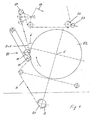
- the figures show a roll changer for web-fed rotary printing presses which is set up to receive two rolls of paper R1 and R2. It has a first roller arm 1 which rotatably supports the roller R1 about a rotation axis 4.
- the roller R1 forms a working roll from which a working web A drawn into the printing press unwinds.
- the other roller R2 is also rotatably mounted on a second roller arm 2 about an axis of rotation 5 formed by this roller arm 2.
- the second roll R2 is a supply roll of a supply web V, which is to replace the almost used work roll R1.
- a motor M1 forms a rotary drive for the work roll R1, which rotates the work roll R1 about the rotation axis 4 during operation of the machine.
- a similar motor M2 forms a rotary drive for the supply roll R2 in order to drive the supply roll R2 about its axis of rotation 5.
- the two roller arms 1 and 2 form aligned pivot arms about a common pivot axis 3.
- Another motor M3 forms a pivot drive for pivoting the roller arms 1 and 2 about the pivot axis 3.
- the roller arm 2 in the for the roller arm. 1 be pivoted in the figures shown pivot position.
- two guide rollers 9 are pivotable on pivot arms about the pivot axis 3.
- the pivot arms for the guide rollers 9 are torsionally rigidly connected to the roller arms 1 and 2 and form a cross with these.
- the reel changer comprises a connecting device 10, a pulling device 16 and a holding device 21 along a path formed for the working path A.
- the connecting device 10 is designed as an adhesive device. It comprises, as a joining element, an adhesive roller 14, which is rotatably mounted on a pivoting arm 11 of the supply roll R2 opposite.
- the pivot arm 11 is pivotable about a pivot axis 12 which is parallel to the axis of rotation 5 of the supply roll R2.
- the axis of rotation of the adhesive roller 14 has parallel to the axis of rotation 5.
- the adhesive roller 14 is, as in FIG. 1 indicated, by means of the pivoting movement about the pivot axis 12 to the supply roll R2 pressed.
- the pivoting movement towards the supply roll R2 and away from the supply roll R2 is effected by means of a pivot drive 13, which is formed by a piston-fluid-cylinder arrangement.
- the working web A is guided in the position of the work roll R1 shown in the figures between the supply roll R2 and the adhesive roll 14.
- the pulling device 16 In the path of the work A, immediately behind the connecting device 10, the pulling device 16 is arranged.
- the pulling device 16 comprises a cylinder body 17, which is pivotably mounted on a pivoting arm about a pivot axis 18.
- the cylinder body 17 is freely rotatably mounted about its longitudinal axis and is formed in the embodiment of a web-width roller body.
- the working path A wraps around the cylinder body 17 with a wrap angle of more than 90 ° and is deflected down the track of the cylinder body 17 about a guide roller 20.
- the working path A is freely stretched between the guide roller 9 of the roller bearing and the cylinder body 17, i. There are no other deflecting elements in this part of the railway.
- Only the connecting device 10 acts to produce the joint connection in this track section on the working path A. Basically, however, before and / or behind the connecting device 10 further deflecting be arranged.
- the cylinder body 17 preferably forms a per se known pendulum roller, as in the embodiment, which serves to compensate for web tension fluctuations.
- the cylinder body 17 is accordingly against a resilience of a return element, such as a compression spring or a fluidbeaufschlagter cylinder, pivotable about the pivot axis 18, wherein the cylinder body 17 is moved by the wrapping work A due to the web tension against the force of the return element.
- the traction device 16 is equipped with a drive 19, which corresponds to the example selected Pendelwalzenanssen is designed as a pivot drive.
- the drive 19 is preferably a piston-fluid cylinder arrangement and serves to pivot the cylinder body 17 about the pivot axis 18. In the figures, an average normal or nominal position and two positions of the cylinder body 17 located on both sides of the central position are shown.
- the holding device 21 includes a rotationally driven cylinder body 22 which is looped by the working line A.
- the cylinder body 22 as is preferred, a draw roller.
- the working path A is tensioned freely, i. In this track section, there are no further elements acting on the working track A. In principle, however, deflecting bodies can be arranged therebetween.
- the holding device 21 is preferably formed by a home-made pulling device, which is arranged between the tensioning and pulling device 16 and the closest in the web path printing unit of the machine.
- the train roller closest to the tensioning and pulling device 16 forms the cylinder body 22.
- the cylinder body 22 opposite a formed by a clamping element 23 blocking element is arranged, which can be turned off to the cylinder body 22 and from the cylinder body 22, for example by means of a pivotal mounting of the clamping element 23.
- the clamping element 23 when forming the cylinder body 22 as a roller preferably also formed by a roller body which is not rotatable for the purpose of fixing the working path A about its own longitudinal axis.
- the roll changer also comprises a sensor 7 directed onto the surface of the supply roll R2.
- the sensor 7 serves to detect a splice 6 on which a web start of the supply web V is glued to a next web layer of the supply roll R2.
- the control device 24 is used to control and preferably also control of the drives M1, M2, M3, 13 and 19, a rotary drive for the cylinder body 22 and a drive for switching on and off of the clamping element 23.
- the corresponding connections with the said drives for transmission the control signals are shown in dotted lines.
- the connection can in each case be wired or wireless, for example by radio or optical, executed.
- the roll change is carried out automatically at least after an optionally manual insertion of the supply roll R2 and removal of the old, for example, used work roll R1. This applies to a flying reel change during production and, according to the invention, also for a reel change to be performed at standstill of the reel changer.
- FIG. 1 shows the reel changer with retracted work A.
- the unwound from the work roll R1 working web A is first passed through the one of the guide rollers 9 and between the supply roll R2 and the connecting device 10 through to the tensioning and pulling device 16, wraps around the cylinder body 17 by about 140 °, is deflected immediately behind the cylinder body 17 from the guide roller 20 to the cylinder body 22 of the holding device 21, wraps around the cylinder body 22 by preferably at least 90 ° and is finally guided from there through the first printing nip of the printing press.
- FIG. 1 shows the reel changer with retracted work A.
- the pivot arm 11 with the adhesive roller 14 is in an initial position in which the working path A is not touched, that is, the working path A runs freely in the state shown between the supply roll R2 and the connecting device 10.
- the cylinder body 17 of the tensioning and pulling device 16 is held by the drive of the work roll R1 by means of the working web A, ie by their web tension, in a forward position in which the web path between the next adjacent guide rollers 9 and 20 on both sides of the cylinder body 17th has its smallest length.
- the working path A is already fixed by the holding device 21 by the clamping element 23 is pressed with a pressing force against the cylinder body 22 and the web A is firmly clamped in the nip formed between the cylinder body 22 and the surface preferably elastically resilient clamping member 23 formed.
- the supply roll R2 takes in the in FIG. 1 shown state of the reel changer already a defined rotational position.
- the supply roll R2 was previously rotated in the illustrated pivot position by means of the motor M2.
- the splice 6 was detected by means of the sensor 7 and determined by the control device 24.
- the motor M2 controlled by the controller 24 in the illustrated rotational angular position with the rotational position angle ⁇ rotated and preferably set in this rotational position.
- the rotational position angle ⁇ defining this rotational position is the Measured in angular degrees distance, the splice 6 from the contact point of the adhesive roller 14 has when the adhesive roller 14 is pressed against the supply roll R2.
- FIG. 2 shows the state of the roll changer after the adhesive roller 14 has been pivoted about the pivot axis 12 and turned against the supply roll R2 and is now pressed against its surface. Otherwise take all other elements of the roll changer including the holding device 21 still the same positions as in the state of FIG. 1 one. If necessary, the work roller R1 was rotated a little by pressing.
- FIG. 3 shows the entire arrangement, after the work path A by means of the pulling device 16 already a distance from the in FIG. 2 shown state has been deducted from the work roll R1.
- the cylinder body 17 of the drive 19 In order to exert the necessary tensile force on the work A, the cylinder body 17 of the drive 19 about the pivot axis 18 and against the web tension in the in FIG. 3 shown, middle target position pivoted. This setpoint position assumes the cylinder body 17 during operation also, but pivots freely according to the interaction of the web tension and the return element.
- the rotational movement of the work roll R1 by means of the motor M1 and / or a brake 8 is controlled so that adjusts a favorable web tension and Auszugs familia.
- an additional brake 8 is not required in this case. Rather, it is driven during the extraction of the working path A of the motor M1 at a defined speed or even works as a brake generator, and it is the cylinder body 17 acted upon by the drive 19 with a defined restoring force, so that the cylinder body 17 assumes the middle target position.
- the pull-out movement of the working line A is in FIG. 3 indicated with two solid arrows in the railway.
- the supply roll R1 is due to the friction caused by means of the pressing adhesive roller 14 from their in the FIGS. 1 and 2 shown angular position in the in FIG. 3 shown rotational position has been rotated, in which the splice 6 comes to rest under the adhesive roller 14. Since the splice 6 has been previously made “sharp", the working web A is pressed by the adhesive roller 14 firmly against the splice 6 having web start of the supply web V in the rotational angle position shown and thereby the web start of the supply web V glued to the work path A.
- the braking force of the brake 8 is adjusted by the control device 24 in accordance with the pivoting movement of the cylinder body 17 of the pulling device 16.
- the tuning is such that the braking force of the brake 8 is set so that the cylinder 17 of the pulling device 16 performs a pivoting movement at a defined speed up to a rear position, which in FIG. 4 is shown in a solid line.
- the motor M1 can be operated as a brake generator.
- a motor for both directions of rotation form the motor M1.
- Such a motor with reversible directions of rotation may additionally be designed as a brake generator.
- FIG. 4 shows in the sequence the state in which the cylinder body 17 assumes its rear position and the working path A has therefore been pulled out during the standstill roll change by the maximum extension length.
- the adhesive roller 14 is pressed against the supply roll R2. After making the connection, which is primarily in the in FIG. 3 shown state is effected by the further pressing of the adhesive roller 14 a clean detachment of the web start of the supply web V of the supply roll R2. In the in FIG. 4 shown state of the web beginning of the supply web V is already detached from the supply roll R2.
- FIG. 4 shows the old work A immediately after the cap.
- the connecting device 10 is again turned off by the supply roll R2. Subsequently, the cylinder body 17 by the drive M1 of the work roll R1 from his in FIG. 4 shown rear position back to the middle position (target position) moves, the cylinder body 17 also occupies the later operation of the machine or to which it oscillates in the event of web fluctuations.
- the work A is still fixed by the holding and pulling device 21 while.
- the supply roll R2 from which the working web subsequently unwinds, is turned back in order to keep the web tension constant or at least substantially constant.
- the reverse rotation is indicated by the indicated rotary arrow.
- the role change is in this, in FIG. 5 displayed state completed.
- the drive 19 is a pneumatic drive, it can also form the return element for the elastic compensation of web fluctuations. However, it has no elasticity, because it is formed for example by a hydraulic drive or electric drive, such a drive 19 is disengaged for the purpose of web tension compensation during machine operation.
Claims (13)
- Echangeur de rouleaux pour une machine d'usinage ou de traitement de bandes, qui est aménagé pour un déroulement d'une bande de travail (A), à usiner ou à traiter, depuis un rouleau de travail (R1), et pour un raccordement d'une bande de réserve (V), depuis un rouleau de réserve (R2), à la bande de travail (A), l'échangeur de rouleaux comprenant :a) un premier support (1, 4) pour le rouleau de travail (R1), et un deuxième support (2, 5) pour le rouleau de réserve (R2),b) un équipement de raccordement (10) pour le raccordement de la bande de réserve (V) à la bande de travail (A),c) un équipement de retenue (21) disposé en aval, sur la bande, de l'équipement de raccordement (10) pour une fixation de la bande de travail (A), caractérisé parun équipement de traction (16) qui est disposé sur une course de bande de la bande de travail (A) entre l'équipement de raccordement (10) et l'équipement de retenue (21), et qui est aménagé pour tirer la bande de travail (A), à partir de l'arrêt du rouleau de travail (R1), depuis le rouleau de travail (R1).
- Echangeur de rouleaux selon la revendication 1, caractérisé en ce qu'un équipement de tension, qui sert à compenser des variations de tension de bande pendant la production de la machine, forme l'équipement de traction (16).
- Echangeur de rouleaux selon une des revendications précédentes, caractérisé en ce que l'équipement de traction (16) comprend au moins un corps cylindrique (17) et un entraînement (19), au moyen duquel le corps cylindrique (17) est mobile transversalement à la bande de travail (A) pour tirer la bande de travail (A) depuis le rouleau de travail (R1).
- Echangeur de rouleaux selon la revendication précédente, caractérisé en ce que le corps cylindrique (17) est supporté de façon mobile, contre une force élastique d'un équipement de rappel, transversalement à son axe longitudinal, la force élastique agissant contre une force qui agit depuis la bande de travail (A) sur le corps cylindrique (17).
- Echangeur de rouleaux selon une des deux revendications précédentes, caractérisé en ce qu'un cylindre compensateur, qui est supporté de façon mobile, de préférence de façon pivotante, transversalement à la bande de travail (A), forme le corps cylindrique (17).
- Echangeur de rouleaux selon une des revendications précédentes, caractérisé en ce que l'équipement de raccordement (10) est disposé en face du rouleau de réserve (R2) situé dans une position d'assemblage, et est supporté de façon à pouvoir être posé contre le rouleau de réserve (R2).
- Echangeur de rouleaux selon une des revendications précédentes, caractérisé en ce que l'équipement de retenue (21) comprend un élément de traction (22) pour un déplacement de la bande de travail (A), ou bien est déjà formé uniquement de l'élément de traction (22).
- Echangeur de rouleaux selon la revendication précédente, caractérisé en ce que l'équipement de retenue (21) comprend un élément de serrage (23) pouvant être pressé contre l'élément de traction (22) pour la fixation de la bande de travail (A) provoquée par le serrage entre l'élément de traction (22) et l'élément de serrage (23).
- Echangeur de rouleaux selon une des revendications précédentes, caractérisé en ce qu'un équipement de traction, qui est disposé, sur la course de bande de la bande de travail (A), devant un équipement d'usinage ou de traitement de la machine suivant l'échangeur de rouleaux, forme l'équipement de retenue (21).
- Echangeur de rouleaux selon une des revendications précédentes, caractérisé en ce qu'un moteur (M1) pour un entraînement rotatif du rouleau de travail (R1) est constitué en tant que frein générateur.
- Procédé pour un changement automatique de rouleaux dans une machine d'usinage ou de traitement de bandes, dans lequel :a) un rouleau de réserve (R2) d'une bande de réserve (V) est déplacé jusque dans une position d'assemblage par rapport à une bande de travail (A) introduite dans la machine, et qui se déroule depuis un rouleau de travail (R1),b) la bande de travail (A) est pressée sur un début de bande du rouleau de réserve (R2), et est raccordée au début de bande,c) la bande de travail (A) est fixée en aval, sur la bande, du début de bande du rouleau de réserve (R2), caractérisé en ce qued) une force de traction est exercée sur la bande de travail (A) fixée, dans un emplacement entre le début de bande du rouleau de réserve (R2) et l'emplacement de la fixation, et à travers la bande de travail (A) est tirée du rouleau de travail (R1),e) le rouleau de réserve (R2) est tourné, lors de la traction de la bande de travail (A), par pression sur la bande de travail (A) ou par un entraînement propre,f) et la bande de travail (A) est sectionnée, après la réalisation du raccordement, dans un emplacement entre le rouleau de travail (R1) et le début de bande du rouleau de réserve (R2).
- Procédé selon la revendication précédente, caractérisé en ce que la bande de travail (A) pressée sur le rouleau de réserve (R2) est tendue par freinage ou par entraînement contrôlé du rouleau de travail (R1).
- Procédé selon une des revendications précédentes, caractérisé en ce que le rouleau de réserve (R2), après le sectionnement de la bande de travail (A), alors que persiste la fixation, est tourné en arrière à l'inverse du sens de déplacement de la bande de réserve (V) formant une nouvelle bande de travail, pour tendre la nouvelle bande de travail.
Applications Claiming Priority (2)
| Application Number | Priority Date | Filing Date | Title |
|---|---|---|---|
| DE10146631A DE10146631B4 (de) | 2001-09-21 | 2001-09-21 | Rollenwechsler und Verfahren für einen automatischen Rollenwechsel im Stillstand |
| DE10146631 | 2001-09-21 |
Publications (4)
| Publication Number | Publication Date |
|---|---|
| EP1295830A2 EP1295830A2 (fr) | 2003-03-26 |
| EP1295830A3 EP1295830A3 (fr) | 2005-01-26 |
| EP1295830B1 EP1295830B1 (fr) | 2007-03-21 |
| EP1295830B2 true EP1295830B2 (fr) | 2009-06-17 |
Family
ID=7699843
Family Applications (1)
| Application Number | Title | Priority Date | Filing Date |
|---|---|---|---|
| EP02405806A Expired - Lifetime EP1295830B2 (fr) | 2001-09-21 | 2002-09-17 | Echangeur de rouleaux et méthode pour le changement automatique de rouleaux pendat l'arrêt |
Country Status (5)
| Country | Link |
|---|---|
| US (1) | US6729573B2 (fr) |
| EP (1) | EP1295830B2 (fr) |
| AT (1) | ATE357395T1 (fr) |
| DE (2) | DE10146631B4 (fr) |
| ES (1) | ES2284804T5 (fr) |
Families Citing this family (8)
| Publication number | Priority date | Publication date | Assignee | Title |
|---|---|---|---|---|
| JP3539565B2 (ja) * | 2002-02-05 | 2004-07-07 | 株式会社東京機械製作所 | 輪転機のウェブ紙保持装置 |
| ITFI20040016A1 (it) * | 2004-01-21 | 2004-04-21 | Perini Fabio Spa | Dispositivo svolgitore per bobine di materiale nastriforme e relativo metodo |
| ITFI20060156A1 (it) * | 2006-06-21 | 2007-12-22 | Focus S R L | Apparato di alimentazione di un materiale in forma di nastro continuo ad una o piu' macchine operatrici |
| DE102008000242B3 (de) * | 2008-02-06 | 2009-01-22 | Koenig & Bauer Aktiengesellschaft | Verfahren zum Stillstandsrollenwechsel in einem für einen fliegenden Rollenwechsel ausgelegten Rollenwechsler |
| DE102008028165A1 (de) * | 2008-06-12 | 2009-12-17 | Manroland Ag | Rollenwechsler für eine Rollendruckmaschine und Verfahren zum Betreiben dessen |
| DE102011007457A1 (de) * | 2011-04-15 | 2012-10-18 | Robert Bosch Gmbh | Verfahren und Vorrichtung zur Verbindung von zwei Folienbahnen |
| DE102011084935A1 (de) * | 2011-10-21 | 2013-04-25 | Koenig & Bauer Aktiengesellschaft | Verfahren zum Einziehen zumindest einer Materialbahn in eine Verarbeitungsvorrichtung |
| PL3392029T3 (pl) | 2017-04-21 | 2022-04-25 | Held Technologie Gmbh | Podajnik do dwutaśmowej prasy, układ dwutaśmowej prasy i sposób użytkowania |
Citations (3)
| Publication number | Priority date | Publication date | Assignee | Title |
|---|---|---|---|---|
| US4453152A (en) † | 1983-01-10 | 1984-06-05 | The Singer Company | Sewing machine control |
| US5253819A (en) † | 1991-09-04 | 1993-10-19 | Butler Automatic, Inc. | Speed match splicing method and apparatus |
| EP1223134A2 (fr) † | 2000-12-07 | 2002-07-17 | Heidelberger Druckmaschinen Aktiengesellschaft | Changeur de bobines à la volée dans une imprimante rotative |
Family Cites Families (14)
| Publication number | Priority date | Publication date | Assignee | Title |
|---|---|---|---|---|
| BE639827A (fr) * | 1962-11-13 | |||
| US3279716A (en) * | 1963-09-09 | 1966-10-18 | William F Huck | Continuous web winding rollstand |
| US3326486A (en) * | 1965-09-02 | 1967-06-20 | Huck William F | Automatic controls for splicing rollstand |
| US3391877A (en) * | 1966-09-28 | 1968-07-09 | Hurletron Inc | Automatic preprint paster apparatus and method for using same |
| JPS5931244A (ja) * | 1982-08-09 | 1984-02-20 | Dainippon Printing Co Ltd | 給紙装置の紙継ぎ方法 |
| DE3440107A1 (de) * | 1984-11-02 | 1986-05-22 | Jagenberg AG, 4000 Düsseldorf | Verfahren und vorrichtung zum verbinden einer ersten, zu einer verarbeitungsmaschine ablaufenden materialbahn mit dem anfang einer aufgewickelten zweiten materialbahn |
| DE3601296A1 (de) * | 1986-01-17 | 1987-07-23 | Waertsilae Strecker Gmbh | Vorrichtung zum automatischen ansetzen einer warenbahn in einer beschickungsvorrichtung |
| DE3723600A1 (de) * | 1987-07-17 | 1989-01-26 | Voith Gmbh J M | Abwickelvorrichtung fuer papier- oder kartonbahn |
| DE3931852A1 (de) * | 1989-09-23 | 1991-04-04 | Erhardt & Leimer Gmbh | Rollenwechsler |
| DE4000745A1 (de) * | 1990-01-12 | 1991-07-18 | Roland Man Druckmasch | Rollenwechselvorrichtung fuer eine druckmaschine |
| US5064488A (en) * | 1990-03-27 | 1991-11-12 | Trine Manufacturing Company, Inc. | Apparatus and method for splicing film |
| JPH0671954B2 (ja) * | 1990-11-29 | 1994-09-14 | 株式会社東京機械製作所 | 紙継装置 |
| US5514237A (en) * | 1993-10-05 | 1996-05-07 | The Procter & Gamble Company | Heat splicing of thermoplastic film |
| JP2943106B1 (ja) * | 1998-05-18 | 1999-08-30 | 株式会社東京機械製作所 | 走行ウエブの制振方法、制振装置及び紙継ぎ補助装置 |
-
2001
- 2001-09-21 DE DE10146631A patent/DE10146631B4/de not_active Expired - Fee Related
-
2002
- 2002-09-17 ES ES02405806T patent/ES2284804T5/es not_active Expired - Lifetime
- 2002-09-17 EP EP02405806A patent/EP1295830B2/fr not_active Expired - Lifetime
- 2002-09-17 DE DE50209753T patent/DE50209753D1/de not_active Expired - Lifetime
- 2002-09-17 AT AT02405806T patent/ATE357395T1/de not_active IP Right Cessation
- 2002-09-19 US US10/247,133 patent/US6729573B2/en not_active Expired - Fee Related
Patent Citations (3)
| Publication number | Priority date | Publication date | Assignee | Title |
|---|---|---|---|---|
| US4453152A (en) † | 1983-01-10 | 1984-06-05 | The Singer Company | Sewing machine control |
| US5253819A (en) † | 1991-09-04 | 1993-10-19 | Butler Automatic, Inc. | Speed match splicing method and apparatus |
| EP1223134A2 (fr) † | 2000-12-07 | 2002-07-17 | Heidelberger Druckmaschinen Aktiengesellschaft | Changeur de bobines à la volée dans une imprimante rotative |
Also Published As
| Publication number | Publication date |
|---|---|
| EP1295830B1 (fr) | 2007-03-21 |
| ATE357395T1 (de) | 2007-04-15 |
| DE10146631B4 (de) | 2004-03-04 |
| DE10146631A1 (de) | 2003-04-10 |
| DE50209753D1 (de) | 2007-05-03 |
| ES2284804T5 (es) | 2009-10-15 |
| EP1295830A2 (fr) | 2003-03-26 |
| US20030057315A1 (en) | 2003-03-27 |
| US6729573B2 (en) | 2004-05-04 |
| ES2284804T3 (es) | 2007-11-16 |
| EP1295830A3 (fr) | 2005-01-26 |
Similar Documents
| Publication | Publication Date | Title |
|---|---|---|
| DE2430514C3 (de) | Vorrichtung zum Verbinden einer von einer Ersatzwickelrolle abgezogenen Materialbahn mit einer von einer Vorratswickelrolle ablaufenden Materialbahn | |
| DE3723601C2 (fr) | ||
| DE4141242C2 (fr) | ||
| DE2644298A1 (de) | Vorrichtung zum anschliessen einer bobine aus papier oder einem anderen material an eine andere bobine | |
| DE19608842B4 (de) | Vorrichtung und Verfahren für den Bahneinzug | |
| DE102006015477B3 (de) | Vorrichtung zum Ersetzen einer ersten Materialbahn durch eine zweite Materialbahn | |
| EP1295830B2 (fr) | Echangeur de rouleaux et méthode pour le changement automatique de rouleaux pendat l'arrêt | |
| EP0578956A1 (fr) | Dispositif de raccordement de deux bandes | |
| EP2465362A2 (fr) | Dispositif de traitement d'une bande de papier à utiliser pour la fabrication d'articles à fumer en forme de tiges | |
| DE102006042217B4 (de) | In einem Rollenwechsler für eine Rollendruckmaschine durchgeführtes Verfahren zum Verbinden einer ersten Materialbahn mit einer zweiten Materialbahn | |
| DE2344870C3 (de) | Vorrichtung zur endweisen Verbindung zweier Bahnen | |
| DE102008000242B3 (de) | Verfahren zum Stillstandsrollenwechsel in einem für einen fliegenden Rollenwechsel ausgelegten Rollenwechsler | |
| DE69914868T2 (de) | Automatischer Spleisser für Abwickler | |
| EP2285719B1 (fr) | Procédé et dispositif de déroulement de matériau en forme de bande et machine de traitement de bande | |
| DE19704332B4 (de) | Vorrichtung zum Bearbeiten von mindestens zwei Materialbahnen aus Papier oder Kunststoffolie | |
| DE3440107C2 (fr) | ||
| DE2417515C2 (de) | Vorrichtung zum Zuführen einer Hüllmaterialbahn zu einem Förderer in einer Zigarettenverpackungsmaschine | |
| EP0963909A1 (fr) | Procédé et dispositif pour fabriquer un rouleau de matériau en bande emballée circonférenciellement, et un rouleau de matériau en bande | |
| EP1335872B1 (fr) | Dispositif pour assembler deux bandes de materiau | |
| DE10219611B4 (de) | Rollenwechsler | |
| DE102013209559B4 (de) | Vorrichtung zum Aufrollen einer Materialbahn zu einer Rolle und Verfahren zur Verwendung dieser Vorrichtung | |
| DE102008022702B4 (de) | Verfahren und eine Vorrichtung zum Abwickeln und zum Speichern von bahnförmigem Material | |
| DE10058437B4 (de) | Vorrichtungen zum Verbinden zweier Materialbahnen | |
| EP3405421B1 (fr) | Dispositif et procédé de changement d'une bobine et de liaison d'une nouvelle bande de matériau à une extrémité d'une ancienne bande de matériau | |
| EP1048599A2 (fr) | Dispositif pour alimenter un matériau continu vers une machine à imprimer |
Legal Events
| Date | Code | Title | Description |
|---|---|---|---|
| PUAI | Public reference made under article 153(3) epc to a published international application that has entered the european phase |
Free format text: ORIGINAL CODE: 0009012 |
|
| AK | Designated contracting states |
Kind code of ref document: A2 Designated state(s): AT BE BG CH CY CZ DE DK EE ES FI FR GB GR IE IT LI LU MC NL PT SE SK TR |
|
| AX | Request for extension of the european patent |
Extension state: AL LT LV MK RO SI |
|
| PUAL | Search report despatched |
Free format text: ORIGINAL CODE: 0009013 |
|
| AK | Designated contracting states |
Kind code of ref document: A3 Designated state(s): AT BE BG CH CY CZ DE DK EE ES FI FR GB GR IE IT LI LU MC NL PT SE SK TR |
|
| AX | Request for extension of the european patent |
Extension state: AL LT LV MK RO SI |
|
| 17P | Request for examination filed |
Effective date: 20050726 |
|
| AKX | Designation fees paid |
Designated state(s): AT BE BG CH CY CZ DE DK EE ES FI FR GB GR IE IT LI LU MC NL PT SE SK TR |
|
| GRAP | Despatch of communication of intention to grant a patent |
Free format text: ORIGINAL CODE: EPIDOSNIGR1 |
|
| GRAS | Grant fee paid |
Free format text: ORIGINAL CODE: EPIDOSNIGR3 |
|
| GRAA | (expected) grant |
Free format text: ORIGINAL CODE: 0009210 |
|
| AK | Designated contracting states |
Kind code of ref document: B1 Designated state(s): AT BE BG CH CY CZ DE DK EE ES FI FR GB GR IE IT LI LU MC NL PT SE SK TR |
|
| PG25 | Lapsed in a contracting state [announced via postgrant information from national office to epo] |
Ref country code: IE Free format text: LAPSE BECAUSE OF FAILURE TO SUBMIT A TRANSLATION OF THE DESCRIPTION OR TO PAY THE FEE WITHIN THE PRESCRIBED TIME-LIMIT Effective date: 20070321 |
|
| REG | Reference to a national code |
Ref country code: GB Ref legal event code: FG4D Free format text: NOT ENGLISH |
|
| REG | Reference to a national code |
Ref country code: CH Ref legal event code: EP |
|
| REF | Corresponds to: |
Ref document number: 50209753 Country of ref document: DE Date of ref document: 20070503 Kind code of ref document: P |
|
| REG | Reference to a national code |
Ref country code: IE Ref legal event code: FG4D Free format text: LANGUAGE OF EP DOCUMENT: GERMAN |
|
| GBT | Gb: translation of ep patent filed (gb section 77(6)(a)/1977) |
Effective date: 20070531 |
|
| REG | Reference to a national code |
Ref country code: SE Ref legal event code: TRGR |
|
| ET | Fr: translation filed | ||
| PG25 | Lapsed in a contracting state [announced via postgrant information from national office to epo] |
Ref country code: PT Free format text: LAPSE BECAUSE OF FAILURE TO SUBMIT A TRANSLATION OF THE DESCRIPTION OR TO PAY THE FEE WITHIN THE PRESCRIBED TIME-LIMIT Effective date: 20070821 |
|
| REG | Reference to a national code |
Ref country code: IE Ref legal event code: FD4D |
|
| REG | Reference to a national code |
Ref country code: ES Ref legal event code: FG2A Ref document number: 2284804 Country of ref document: ES Kind code of ref document: T3 |
|
| PG25 | Lapsed in a contracting state [announced via postgrant information from national office to epo] |
Ref country code: SK Free format text: LAPSE BECAUSE OF FAILURE TO SUBMIT A TRANSLATION OF THE DESCRIPTION OR TO PAY THE FEE WITHIN THE PRESCRIBED TIME-LIMIT Effective date: 20070321 |
|
| PG25 | Lapsed in a contracting state [announced via postgrant information from national office to epo] |
Ref country code: CZ Free format text: LAPSE BECAUSE OF FAILURE TO SUBMIT A TRANSLATION OF THE DESCRIPTION OR TO PAY THE FEE WITHIN THE PRESCRIBED TIME-LIMIT Effective date: 20070321 |
|
| PLBI | Opposition filed |
Free format text: ORIGINAL CODE: 0009260 |
|
| PLAX | Notice of opposition and request to file observation + time limit sent |
Free format text: ORIGINAL CODE: EPIDOSNOBS2 |
|
| PG25 | Lapsed in a contracting state [announced via postgrant information from national office to epo] |
Ref country code: DK Free format text: LAPSE BECAUSE OF FAILURE TO SUBMIT A TRANSLATION OF THE DESCRIPTION OR TO PAY THE FEE WITHIN THE PRESCRIBED TIME-LIMIT Effective date: 20070321 |
|
| 26 | Opposition filed |
Opponent name: MAN ROLAND DRUCKMASCHINEN AG Effective date: 20071220 |
|
| BERE | Be: lapsed |
Owner name: MASCHINENFABRIK WIFAG Effective date: 20070930 |
|
| NLR1 | Nl: opposition has been filed with the epo |
Opponent name: MAN ROLAND DRUCKMASCHINEN AG |
|
| PG25 | Lapsed in a contracting state [announced via postgrant information from national office to epo] |
Ref country code: GR Free format text: LAPSE BECAUSE OF FAILURE TO SUBMIT A TRANSLATION OF THE DESCRIPTION OR TO PAY THE FEE WITHIN THE PRESCRIBED TIME-LIMIT Effective date: 20070622 Ref country code: MC Free format text: LAPSE BECAUSE OF NON-PAYMENT OF DUE FEES Effective date: 20070930 |
|
| PLBB | Reply of patent proprietor to notice(s) of opposition received |
Free format text: ORIGINAL CODE: EPIDOSNOBS3 |
|
| PLAB | Opposition data, opponent's data or that of the opponent's representative modified |
Free format text: ORIGINAL CODE: 0009299OPPO |
|
| PG25 | Lapsed in a contracting state [announced via postgrant information from national office to epo] |
Ref country code: BE Free format text: LAPSE BECAUSE OF NON-PAYMENT OF DUE FEES Effective date: 20070930 |
|
| PLAB | Opposition data, opponent's data or that of the opponent's representative modified |
Free format text: ORIGINAL CODE: 0009299OPPO |
|
| R26 | Opposition filed (corrected) |
Opponent name: MANROLAND AG Effective date: 20071220 |
|
| PG25 | Lapsed in a contracting state [announced via postgrant information from national office to epo] |
Ref country code: AT Free format text: LAPSE BECAUSE OF NON-PAYMENT OF DUE FEES Effective date: 20070917 |
|
| NLR1 | Nl: opposition has been filed with the epo |
Opponent name: MANROLAND AG |
|
| PG25 | Lapsed in a contracting state [announced via postgrant information from national office to epo] |
Ref country code: EE Free format text: LAPSE BECAUSE OF FAILURE TO SUBMIT A TRANSLATION OF THE DESCRIPTION OR TO PAY THE FEE WITHIN THE PRESCRIBED TIME-LIMIT Effective date: 20070321 |
|
| PGFP | Annual fee paid to national office [announced via postgrant information from national office to epo] |
Ref country code: SE Payment date: 20080923 Year of fee payment: 7 |
|
| RAP2 | Party data changed (patent owner data changed or rights of a patent transferred) |
Owner name: WIFAG MASCHINENFABRIK AG |
|
| PUAH | Patent maintained in amended form |
Free format text: ORIGINAL CODE: 0009272 |
|
| STAA | Information on the status of an ep patent application or granted ep patent |
Free format text: STATUS: PATENT MAINTAINED AS AMENDED |
|
| REG | Reference to a national code |
Ref country code: CH Ref legal event code: PFA Owner name: WIFAG MASCHINENFABRIK AG Free format text: MASCHINENFABRIK WIFAG#WYLERRINGSTRASSE 39 POSTFACH#3001 BERN (CH) -TRANSFER TO- WIFAG MASCHINENFABRIK AG#WYLERRINGSTRASSE 39 POSTFACH 8865#3001 BERN (CH) |
|
| NLT2 | Nl: modifications (of names), taken from the european patent patent bulletin |
Owner name: WIFAG MASCHINENFABRIK AG Effective date: 20090408 |
|
| 27A | Patent maintained in amended form |
Effective date: 20090617 |
|
| AK | Designated contracting states |
Kind code of ref document: B2 Designated state(s): AT BE BG CH CY CZ DE DK EE ES FI FR GB GR IE IT LI LU MC NL PT SE SK TR |
|
| REG | Reference to a national code |
Ref country code: CH Ref legal event code: AEN Free format text: AUFRECHTERHALTUNG DES PATENTES IN GEAENDERTER FORM |
|
| PG25 | Lapsed in a contracting state [announced via postgrant information from national office to epo] |
Ref country code: CY Free format text: LAPSE BECAUSE OF FAILURE TO SUBMIT A TRANSLATION OF THE DESCRIPTION OR TO PAY THE FEE WITHIN THE PRESCRIBED TIME-LIMIT Effective date: 20070321 |
|
| NLR2 | Nl: decision of opposition |
Effective date: 20090617 |
|
| PG25 | Lapsed in a contracting state [announced via postgrant information from national office to epo] |
Ref country code: LU Free format text: LAPSE BECAUSE OF NON-PAYMENT OF DUE FEES Effective date: 20070917 Ref country code: BG Free format text: LAPSE BECAUSE OF FAILURE TO SUBMIT A TRANSLATION OF THE DESCRIPTION OR TO PAY THE FEE WITHIN THE PRESCRIBED TIME-LIMIT Effective date: 20070621 |
|
| PG25 | Lapsed in a contracting state [announced via postgrant information from national office to epo] |
Ref country code: TR Free format text: LAPSE BECAUSE OF FAILURE TO SUBMIT A TRANSLATION OF THE DESCRIPTION OR TO PAY THE FEE WITHIN THE PRESCRIBED TIME-LIMIT Effective date: 20070321 |
|
| NLR3 | Nl: receipt of modified translations in the netherlands language after an opposition procedure | ||
| REG | Reference to a national code |
Ref country code: ES Ref legal event code: DC2A Date of ref document: 20090728 Kind code of ref document: T5 |
|
| PGFP | Annual fee paid to national office [announced via postgrant information from national office to epo] |
Ref country code: ES Payment date: 20090928 Year of fee payment: 8 |
|
| PGFP | Annual fee paid to national office [announced via postgrant information from national office to epo] |
Ref country code: FI Payment date: 20090923 Year of fee payment: 8 Ref country code: GB Payment date: 20090922 Year of fee payment: 8 Ref country code: NL Payment date: 20090921 Year of fee payment: 8 |
|
| PGFP | Annual fee paid to national office [announced via postgrant information from national office to epo] |
Ref country code: CH Payment date: 20091221 Year of fee payment: 8 |
|
| PGFP | Annual fee paid to national office [announced via postgrant information from national office to epo] |
Ref country code: IT Payment date: 20090925 Year of fee payment: 8 |
|
| REG | Reference to a national code |
Ref country code: NL Ref legal event code: V1 Effective date: 20110401 |
|
| REG | Reference to a national code |
Ref country code: CH Ref legal event code: PL |
|
| GBPC | Gb: european patent ceased through non-payment of renewal fee |
Effective date: 20100917 |
|
| PG25 | Lapsed in a contracting state [announced via postgrant information from national office to epo] |
Ref country code: IT Free format text: LAPSE BECAUSE OF NON-PAYMENT OF DUE FEES Effective date: 20100917 Ref country code: FI Free format text: LAPSE BECAUSE OF NON-PAYMENT OF DUE FEES Effective date: 20100917 |
|
| REG | Reference to a national code |
Ref country code: FR Ref legal event code: ST Effective date: 20110531 |
|
| PG25 | Lapsed in a contracting state [announced via postgrant information from national office to epo] |
Ref country code: CH Free format text: LAPSE BECAUSE OF NON-PAYMENT OF DUE FEES Effective date: 20100930 Ref country code: LI Free format text: LAPSE BECAUSE OF NON-PAYMENT OF DUE FEES Effective date: 20100930 Ref country code: FR Free format text: LAPSE BECAUSE OF NON-PAYMENT OF DUE FEES Effective date: 20100930 |
|
| PG25 | Lapsed in a contracting state [announced via postgrant information from national office to epo] |
Ref country code: NL Free format text: LAPSE BECAUSE OF NON-PAYMENT OF DUE FEES Effective date: 20110401 Ref country code: GB Free format text: LAPSE BECAUSE OF NON-PAYMENT OF DUE FEES Effective date: 20100917 |
|
| PGFP | Annual fee paid to national office [announced via postgrant information from national office to epo] |
Ref country code: FR Payment date: 20091005 Year of fee payment: 8 |
|
| REG | Reference to a national code |
Ref country code: ES Ref legal event code: FD2A Effective date: 20111019 |
|
| PG25 | Lapsed in a contracting state [announced via postgrant information from national office to epo] |
Ref country code: ES Free format text: LAPSE BECAUSE OF NON-PAYMENT OF DUE FEES Effective date: 20100918 |
|
| PG25 | Lapsed in a contracting state [announced via postgrant information from national office to epo] |
Ref country code: SE Free format text: LAPSE BECAUSE OF NON-PAYMENT OF DUE FEES Effective date: 20090918 |
|
| PGFP | Annual fee paid to national office [announced via postgrant information from national office to epo] |
Ref country code: DE Payment date: 20190923 Year of fee payment: 18 |
|
| REG | Reference to a national code |
Ref country code: DE Ref legal event code: R119 Ref document number: 50209753 Country of ref document: DE |
|
| PG25 | Lapsed in a contracting state [announced via postgrant information from national office to epo] |
Ref country code: DE Free format text: LAPSE BECAUSE OF NON-PAYMENT OF DUE FEES Effective date: 20210401 |