EP2465362A2 - Dispositif de traitement d'une bande de papier à utiliser pour la fabrication d'articles à fumer en forme de tiges - Google Patents
Dispositif de traitement d'une bande de papier à utiliser pour la fabrication d'articles à fumer en forme de tiges Download PDFInfo
- Publication number
- EP2465362A2 EP2465362A2 EP11193451A EP11193451A EP2465362A2 EP 2465362 A2 EP2465362 A2 EP 2465362A2 EP 11193451 A EP11193451 A EP 11193451A EP 11193451 A EP11193451 A EP 11193451A EP 2465362 A2 EP2465362 A2 EP 2465362A2
- Authority
- EP
- European Patent Office
- Prior art keywords
- embossing
- paper web
- printing unit
- roller
- unit
- Prior art date
- Legal status (The legal status is an assumption and is not a legal conclusion. Google has not performed a legal analysis and makes no representation as to the accuracy of the status listed.)
- Withdrawn
Links
Images


Classifications
-
- A—HUMAN NECESSITIES
- A24—TOBACCO; CIGARS; CIGARETTES; SIMULATED SMOKING DEVICES; SMOKERS' REQUISITES
- A24C—MACHINES FOR MAKING CIGARS OR CIGARETTES
- A24C5/00—Making cigarettes; Making tipping materials for, or attaching filters or mouthpieces to, cigars or cigarettes
- A24C5/14—Machines of the continuous-rod type
- A24C5/20—Reels; Supports for bobbins; Other accessories
-
- A—HUMAN NECESSITIES
- A24—TOBACCO; CIGARS; CIGARETTES; SIMULATED SMOKING DEVICES; SMOKERS' REQUISITES
- A24C—MACHINES FOR MAKING CIGARS OR CIGARETTES
- A24C5/00—Making cigarettes; Making tipping materials for, or attaching filters or mouthpieces to, cigars or cigarettes
- A24C5/005—Treatment of cigarette paper
Definitions
- the invention relates to an apparatus for processing a paper web to be used for the production of tipping paper and / or cigarette paper for the production of rod-shaped smoking articles, preferably cigarettes, having a first interface for connection to a Bobinenabrollvoriques and for taking over a paper web from the Bobinenabrollvoriques, at least one Processing device for processing the paper web, a second interface for connection to a downstream production machine for the production of rod-shaped smoking articles and for transferring the processed paper web or its sections to the production machine, a guide device for guiding the paper web along a transport path from the first interface to the at least one processing device over to the second interface, wherein the guide device has a feed speed of the paper web affecting first draw roller.
- the filter section In the tobacco processing industry is for the production of a filter section and a tobacco portion having filter cigarette in a filter attachment the filter section is positioned at one end against one end of the tobacco section and the arrangement of the filter section and tobacco section thus formed is enveloped and connected to one another by a covering paper section which overlaps and glues over both sections.
- a paper web is used, which is wound on a paper base and deducted from it for the processing process and fed to the processing process.
- the paper bobbins which are usually supplied by an external manufacturer, is held in a Bobinenabrollstation provided for this purpose, which is connected upstream of the processing device in question here.
- the WO 2009/141217 A1 therefore proposes the use of an embossing device for embossing a paper web in connection with the production of rod-shaped smoking articles in order to produce a filter cigarette with an embossed tipping paper.
- a device for processing a paper web to be used for the production of tipping paper and / or cigarette paper for the production of rod-shaped smoking articles, preferably cigarettes with a first interface for connection to a bobbin roll-off device and for taking over a paper web from the bobbin roll-off device, at least one processing device for processing the paper web, a second interface for connection to a downstream production machine for the production of the rod-shaped smoking article and for transferring the processed Paper web or from its sections to the production machine, a guide device for guiding the paper web along a transport path from the first interface to the at least one processing device over to the second interface, wherein the guide means has a feed speed of the paper web influencing first draw roller, characterized in that the Processing device comprises a stamping and / or printing unit and the first drawing roller is part of the embossing and / or printing unit and in addition to influencing the feed rate of the paper web and to participate in the embossing and / or printing performed by the emboss
- the draw roller is integrated in the embossing and / or printing unit.
- an otherwise provided otherwise in the prior art draw roller is replaced by an existing in the embossing and / or printing unit roller, so that in the invention, the embossing and / or printing unit generates the machine cycle.
- the invention makes use of the knowledge that the implementation of an embossing and / or printing process with the required precision requires the use of a driven roller or roller, whereby a feed is generated in the conveying direction, so as to promote the paper web in the direction of movement.
- the online mode of operation also allows a simple synchronization of printing and / or stamping marks with the further production process.
- the surface of a hitherto unprocessed paper web can be embossed and / or printed with a relatively low constructional outlay and, however, high production output, high flexibility and demanding quality.
- the embossing and / or printing unit provided according to the invention can be designed so that it can only emboss or print, or it can be designed so that it only embosses or only prints as required or a combined embossing unit. and can do printing.
- an embossing tool having an embossing pattern usually formed by protrusions and depressions is used.
- the embossing tool can be provided in its engagement region with a plurality of spaced-apart embossing pattern.
- the desired embossing pattern can then be brought into engagement with the paper web by non-uniform acceleration and / or deceleration of the desired embossing pattern having the paper web, while the paper web is guided past the other engagement region containing non-desired embossing pattern without interference, for example by using a counter-pressure tool with a correspondingly corresponding surface configuration or the embossing tool is temporarily brought at a distance from the paper web with the non-desired embossing pattern-containing portion of its engagement region.
- ultrasound may alternatively or additionally be used.
- the alternative or additional use of a laser device is possible, in particular if a perforation in the paper web is to be produced with the embossing process.
- a gravure printing device can be used for the printing process.
- printing tools can preferably be used pressure rollers.
- the printing process can also be used, for example, for the application of fire retardants.
- the first interface is provided for connection to an external Bobinenabrollvortechnische and to take over a paper web from the Bobinenabrollvortechnische and thus serves as a paper feed.
- the second interface is provided for connection to a downstream production machine for the production of rod-shaped smoking articles and for transferring the processed paper web or its sections to this production machine.
- the downstream production machine to be connected to the second interface may be an external or separate device or station.
- the embossing and / or printing unit is designed for punch-free or perforation-free embossing and / or printing of the paper web, in order to feed the embossed and / or printing unit embossed and / or printed paper web to the downstream production machine in a perforated or perforation-free manner.
- a possibility is created to mark a paper web without perforation and perforation and thereby apply a desired by the customer embossing and / or printing pattern on the paper web.
- the paper web thus processed is used in particular as a tipping paper or wrapping paper for the production of a cigarette, wherein the embossing and / or printing pattern of the cigarette gives a higher-quality, aesthetic appearance, without influencing the degree of ventilation or draw resistance. Because the fact that the embossing and / or printing unit is designed for punch-free or perforation-free embossing and / or printing, the degree of ventilation and the draw resistance of the rod-shaped article of smoking remain unaffected by the embossing or printing process.
- a perforated paper web can be used or, in addition, a perforating device which operates, for example, with a laser be provided for perforating the paper web before or after the embossing and / or printing unit.
- the first draw roller may be formed simultaneously as embossing and / or pressure roller.
- the tension roller is replaced in this preferred embodiment by the embossing and / or pressure roller, which also takes on the feed function of a tension roller in addition to the embossing and / or printing function.
- the embossing and / or pressure unit may comprise at least one embossing and / or pressure element and adjacent thereto, the first tension roller may be arranged as a counter-roller.
- the at least one embossing and / or pressure element should be an embossing and / or pressure roller which is arranged so that it presses the paper web against the intended as a counter-roller draw roller.
- the tension roller is replaced by the counter-roller, which is thus not only used as a support roller for the embossing and / or printing process, but at the same time takes over the feed function of a tension roller.
- the embossing and / or printing unit can be selectively activated or deactivated.
- the embossing and / or printing unit can be selectively activated or deactivated.
- the first tension roller is optionally in a working position for embossing and / or printing the paper web, thus activating the embossing and / or printing unit is, or in an embossing or pressure-free pass let the rest of the paper web, in which thus the embossing and / or printing unit is deactivated, can be brought.
- the tension roller is used as a counter roller in the embossing and / or printing unit
- the embossing and / or pressure element optionally in a working position for embossing and / or printing the paper web, in the thus the embossing and / or printing unit is activated, or in a the embossment or pressure-free let the paper web pass rest position, in which thus the embossing and / or printing unit is deactivated, can be brought.
- the adjustment between the working position and the rest position is preferably realized by a rotation mechanism and / or a translation mechanism.
- a further preferred embodiment of the invention in which the guide device has, in addition to the already mentioned first draw roller, a second draw roller which influences the feed speed of the paper web, is characterized in that the second draw roller can be selectively activated or deactivated. This allows a more flexible operation of the processing device.
- the second tension roller is either in an engaging with the paper web producing working position in which the second tension roller is activated, or in a paper web without engagement pass let rest position in which the second tension roller is disabled, be brought.
- the adjustment between the working position and the rest position is preferably realized by a rotation mechanism and / or a translation mechanism.
- a further development of this embodiment has a control mechanism which deactivates the second draw roller when the embossing and / or printing unit is activated and activates the second draw roller when the embossing and / or printing unit is deactivated.
- the guide device has a, preferably switchable, first paper web edge control unit which, viewed in the direction of movement of the paper web from the first interface to the second interface, upstream of the embossing and / or printing unit.
- first paper web edge control unit which, viewed in the direction of movement of the paper web from the first interface to the second interface, upstream of the embossing and / or printing unit.
- a further preferred embodiment of the invention in which the processing device has an adhesive unit for applying adhesive to the paper web, is characterized in that the embossing and / or printing unit, viewed in the direction of movement of the paper web from the first interface to the second interface, upstream the gluing unit is located.
- the guide device has a, preferably switchable, second paper web edge control unit
- the second paper web edge control unit is located between the embossing and / or printing unit and the gluing unit.
- the processing means comprises a pad unit comprising a roller, preferably a suction roller, and a cutting element arranged downstream of said roller for moving the paper web in the direction of movement of the paper web from the first interface to the second interface discrete sections for the formation of tipping paper
- the embossing and / or printing unit viewed in the direction of movement of the paper web from the first interface to the second interface, upstream of the covering unit. While the cutting element for the production of separate Tamping paper sections from the paper web, the roller keeps the paper web downstream of the embossing and / or printing unit to voltage.
- the aforementioned adhesive unit is located between the embossing and / or printing unit and the covering unit.
- a breaker unit upstream can lie before the second draw roller.
- a suction device can preferably be connected to the embossing and / or printing unit in order to remove the paper web from the embossing and / or printing process of possibly present dust and dirt particles.
- the embossing and / or printing unit has a housing through which the paper web is guided and which is connected to a compressed air source.
- the housing forms a shield of the space in which the embossing and / or printing takes place, against the environment and in particular the other components of the device and also with respect to the downstream production machine and is held by the compressed air source under slight overpressure, whereby a penetration of Tabakkrümeln , Dirt particles and other particles and thus a negative influence on the embossing and / or printing image is prevented by such particles.
- the guide means may comprise a buffer store, preferably a loop box.
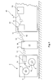
- Fig. 1 is shown schematically in side view part of a plant according to a first embodiment for the production of filter cigarettes, wherein the illustrated part of this Appendix is provided for the processing of a paper web, which is used to form tipping paper and / or cigarette paper for the wrapping of cigarettes.
- the Bobinenabrollstation 2 includes a reel holder with a first bearing pin 4 for receiving and rotatably supporting a first reel 6 and a spaced second bearing pin 8 for receiving and rotatable Storage of a second reel 10.
- a first paper web 12 and on the second reel 10 a second paper web is wound.
- the first paper web 12 is deflected after removal from the first reel 6 on a guide roller 14 and guided to a connection unit 16, which is hereinafter referred to as splicing station.
- the splicing station 16 is intended to connect the trailing end of a paper web from an empty bobbin to the leading end of a paper web from a new bobbin.
- the connection takes place by gluing or knurling.
- the first reel 6 is still relatively full and thus the first paper web 12 has been deducted so far only to a small length. Accordingly, the first bobbin 6 on the in Fig.
- first paper web 12 is hereinafter referred to only as "paper web 12".
- the second reel 10 is a full and unused bobbin whose second paper web is not yet removed and thus unused and not active. Accordingly, in this situation, no deduction movement of the second paper web, which incidentally in Fig.
- the second reel 10 is correspondingly quiet, this state, of course, only lasts until the first paper web 12 has been completely deducted from the first reel 6.
- the trailing end of the first paper web 12 is connected to the leading end or the beginning of the second paper web to be peeled off from the second reel 10, so that subsequently the second paper web forms the active paper web.
- the then empty reel 4 is replaced with a new full reel 6 on the first journal.
- the paper web 12 from the Bobinenabrollstation 2 After leaving the splicing station 16 occurs in the illustrated embodiment, the paper web 12 from the Bobinenabrollstation 2 and is guided to an inlet 18 of an embossing and / or printing station 20, which is the Bobinenabrollstation 2 downstream and another structurally separate component of in Fig. 1 forms shown plant.
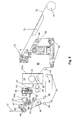
- the embossing and / or printing station 20, which in Fig. 2 is shown in a more detailed single view, is used in the illustrated embodiment to stamp the hitherto unprocessed paper web 12 hole or perforation-free and / or print to apply a desired by the customer embossing and / or printing pattern on the paper web 12.
- the paper web thus processed is used in particular as a tipping paper or wrapping paper for the production of a cigarette, wherein the embossing and / or printing pattern of the cigarette lends a higher-quality, aesthetic appearance, without influencing its degree of ventilation or draw resistance. Accordingly, with the embossing and / or printing station 20, the paper web 12 is not perforated or perforated and the elevations produced by the embossing and / or printing process in the paper web 12 (not shown in the figures) are not opened into holes or perforations. neither in the context of the embossing and / or printing process by the embossing and / or printing station 20, nor in a subsequent process step or in a downstream processing station.
- a perforated paper web can be used if required, or additionally a perforation device, for example, working with a laser, can be provided for perforating the paper web before or after the embossing and / or printing unit.
- the paper web 12 enters through the inlet 18 in the embossing and / or printing station 20 and runs there via a guide roller 22 in a stamping and / or printing unit 24.
- Fig. 2 schematically and in Fig. 3 in an enlarged fragmentary illustration two rollers 25, 26 shown, which may be included in the embossing and / or printing unit 24.
- the two rollers shown by way of example 25, 26, 12 lead the paper web between them and thus on both sides of this for the embossing and / or Pressure applied under a certain contact pressure, one roller is provided as embossing and / or pressure roller and the other roller as a support or counter-roller.
- the roller serving as embossing and / or pressure roller is provided with an embossing pattern usually formed by protrusions or depressions for the embossing process, which is not shown in detail in the figures.
- the intended as embossing and / or pressure roller roller is driven by a drive, not shown, and thus acts on the paper web 12 with a feed to perform the embossing and / or printing process with the required precision.
- a pull roll otherwise provided separately in the prior art is replaced, so that the embossing and / or pressure roller generates the machine cycle.
- the driven embossing and / or pressure roller has the same function as that of a separately provided, the feed speed of the paper web 12 influencing draw roller, so that a separately provided draw roller is basically superfluous.
- rollers 25, 26 are embossing and / or pressure rollers.
- both rollers 25, 26 can be driven jointly or simultaneously by associated drives, not shown in the figures, or a common drive become.
- the roller 26 is optionally in a working position A or a rest position R can be brought.
- the roller 26 In the working position A, the roller 26 is in engagement with the paper web 12, whereby the embossing and / or printing operation is triggered and thus the embossing and / or printing unit 24 is activated.
- the roller 26 In the rest position R, however, the roller 26 is at a distance from the paper web 12; regardless of whether the roller 26 is the embossing and / or pressure roller or the backup roller in the rest position R by the lack of engagement of the roller 26 with the one side of the paper web 12 and an engagement of the roller 25 with the other side of the paper web 12 does not take place, whereby a stamping and / or printing operation is not possible and the embossing and / or printing unit 24 is disabled.
- the roller 26 In the illustrated embodiment according to Fig. 3 the roller 26 is seated at the free end of a pivoting lever 27, which in Fig. 3 only schematically indicated by a dash.
- the pivot lever 27 is pivotally mounted about a stationary pivot bearing 27 a and pivotable by means of a drive, not shown, either in the working position A or the rest position R.
- rollers 25, 26 can be used for the embossing process, in principle, other types of stamping tools with an embossing pattern usually formed by projections and depressions.
- the embossing tool can be provided in its engagement region with a multiplicity of embossed patterns arranged at a distance from one another.
- the desired embossing pattern can then be brought into engagement with the paper web 12 by non-uniform acceleration and / or deceleration of the desired embossing pattern having the paper web 12, while the paper web is guided past the other engagement region containing the unwanted embossing pattern without interference, for example by at the in Fig. 3
- the roller 26 is at least temporarily spent in its rest position R.
- ultrasound may alternatively or additionally be used.
- the alternative or additional use of a laser device is possible, in particular if a perforation in the paper web 12 is to be produced with the embossing process.
- a gravure printing device which is part of the embossing and / or printing unit can be used for the printing process.
- the printing process can also be used, for example, for the application of fire retardants.
- the embossing and / or printing unit 24 can be designed depending on the particular application required so that they can only emboss or only print, or it can be configured so that they only emboss or only print as needed or a combined embossing - And / or printing can perform.
- the embossing and / or printing station 20 should be designed with the embossing and / or printing unit 24 so that it allows unimpeded insertion or removal of the paper web 12, for example, by a quick release and a flying storage of at least a portion of the components the embossing and / or printing unit 24 such as one of the in the FIGS. 2 and 3 schematically shown rollers 25, 26 or both rollers 25, 26 is provided.
- a suction device not shown in the figures may be provided upstream of the embossing and / or printing unit 24 in the embossing and / or printing station 20 to the paper web 12 before the embossing and / or printing of any dust and dirt particles present remove.
- the embossing and / or printing unit 24 has a housing 24a, through which the paper web 12 is guided and which is connected to a compressed air source, also not shown in the figures.
- the housing 24a forms a shield of the space in which the embossing and / or printing takes place, with respect to the environment and in particular with respect to the other components of the embossing and / or printing station 20, the other components of Fig.
- Fig. 2 can also be seen in the embossing and / or printing station 20 shown by way of example downstream after the embossing and / or printing unit 24, a tension compensation device 28 is arranged.
- the Switzerlandwoodsaus GmbHs Republic 28 has a stationary mounted first guide roller 29, a second guide roller 30 which sits at the free end of a pivot axis 31 pivotally mounted pivot arm 32, and a downstream and stationary second deflection roller 33.
- the paper web 12 is guided in the form of a loop, such as Fig. 2 also shows.
- This loop can be extended or shortened by corresponding pivoting of the pivot arm 32, whereby speed and thus tension differences in the paper web 12 are compensated in a known manner.
- the pivot arm 32 is resiliently biased.
- the tension compensation device 28 the influences of the embossing and / or printing unit 24 and a subordinate in the secondary web run and in Fig. 1 schematically shown further processing device 40 decoupled and thus the web tension in the paper web 12 is kept substantially constant.
- the paper web 12 After leaving the tension compensation device 28, the paper web 12 passes another guide roller 22, which in the illustrated embodiment according to Fig. 2 selectively redirecting the paper web 12 to an outlet 36 disposed in an upper position or to an alternative outlet 36a in a lower position, as in FIG Fig. 2 is indicated by a by the reference numeral "12a" marked and dashed line.
- the outlet 36 or 36a is an interface for connection to the in Fig. 1 shown further processing device 40th
- rollers 22, 29, 30 and 33 thus define in the embossing and / or printing station 20 in the figures unspecified transport path and guide means for the movement and guidance of the paper web 12 from the inlet 18 to the outlet 36 and 36a.
- this unspecified transport path and guide device can for temporary storage of the paper web 12, in particular for the purpose of a strain relief, still be a buffer, which is preferably designed as a loop box, but not shown in the figures. Conveniently, such a buffer between the inlet 18 and the embossing and / or printing unit 24 is to be arranged.
- Fig. 1 can be seen schematically, after exiting the outlet 36 of the embossing and / or printing station 20, the paper web 12 is passed into the inlet 42 of the downstream further processing device 40 to be further processed there. After passing through an input station 44 contained in the processing device 40, which has guide rollers and in Fig. 1 2, in the processing device 40, the paper web 12 is subjected to further processing, in particular by gluing it on and, in a coating apparatus 76, cutting it into discrete sections to form tipping paper or cigarette paper.
- the processing device 40 may include a filter tappet, not shown in the figures, in which a filter section is positioned with one end against one end of a tobacco section and the filter section and tobacco section arrangement thus formed with a tipping paper cut from the paper web 12 and glued over both sections wrapped and connected.
- the Filteransetzer is arranged downstream of the processing device 40 as a separate station.
- FIGS. 4 and 5 schematically a processing device 40 is shown according to another embodiment.
- the second embodiment differs according to Fig. 4 from the first embodiment according to Fig. 1 in that the embossing and / or printing station 20 is not connected upstream of the processing device 40 as a separate station, but is integrated into it and thus forms a component of the further processing device 40.
- the inlet of the processing device 40 is directly at the outlet of in Fig. 1 Bobinenabrollstation 2 shown connected.
- FIG Fig. 5 The structure of such a processing apparatus 40 according to the second embodiment is exemplified in FIG Fig. 5 shown.
- the paper web 12 in the illustrated embodiment according to Fig. 5 passed over an input roller 44 forming the input station. From the input roller 44, the paper web 12 runs past a splice detection device 46 to a guide roller 48, from which it is passed through a switchable first paper web edge control unit 50, which in Fig. 5 only schematically indicated by two rollers. Downstream of the first paper web edge control unit 50, the paper web 12, after deflection via further guide rollers 48, passes through a suction device 52 in order to remove the paper web 12 from any dust or dirt particles that may be present.
- the paper web 12 passes between a first Switzerlandwalzencru 54, from the rollers at least one roller is rotated by a drive, not shown in rotation to subject the paper web 12 of a feed movement.
- Fig. 5 can recognize the one roller 54a of the first Werwalzencrues 54 at the free end of a pivot axis 55 pivotally mounted pivot lever 56 is rotatably arranged.
- the pivot lever 56 is between a in Fig. 5 shown working position in which the roller 54a is applied under slight contact pressure on the roller 54b with guided therebetween paper web 12, and a in Fig. 5 Not shown rest position in which the roller 54a is located at a distance from the roller 54b, pivotable by a drive 57 shown schematically.
- the first Switzerlandwalzencrurect 54 is activated while it is deactivated in the rest position of the pivot lever 56 and generates no feed movement.
- the paper web 12 After deflection on the roller 54b of the first Switzerlandwalzenpases 54, the paper web 12 passes to a switchable breaker unit 58 and is sharply deflected there at a crusher blade 59 to produce a Vorkrümmung in the paper web 12 and thus also in the tiling paper to be formed therefrom.
- the paper web 12 is guided by a crusher relief device 60, which has a deflection roller 61, on which the paper web 12 is deflected and which sits at the free end of a swivel axis pivotally mounted about a pivot arm 62.
- the pivot arm 62 which is also referred to as dancer lever, can be pivoted by a drive, not shown.
- the pivot arm 62 may be resiliently biased. Characterized that relieved by appropriate pivoting of the pivot arm 62, the paper web 12 and thus the tension in the paper web 12 and the pressure of the paper web 12 against the crusher blade 59 of the breaker unit 58 repealed or at least significantly reduced, can be with the help of the crusher relief device 60, the effect the breaker unit 58 at least temporarily cancel. This is particularly necessary when a splice point, by which an old paper web is connected to a new paper web, passes by the breaker blade 59 of the breaker unit 58 in order to avoid tearing of the paper web. Therefore, the control of the crusher relief device 60 is performed in cooperation with the splice point detection device 46.
- the second Switzerlandwalzencru 64 can be constructed as the first Switzerlandwalzencru 54 and also activated and deactivated so that reference is made to avoid repetition of the above description of the first Switzerlandwalzencrues 54.
- the paper web 12 After deflection at the second Switzerlandwalzencru 64, the paper web 12 then passes into the embossing and / or printing unit 24.
- the embossing and / or printing unit 24 corresponds in terms of their construction and their mode of action in the FIGS. 2 and 3 shown embossing and / or printing unit 24, so that in order to avoid repetition on the previously using the FIGS. 2 and 3 description is made of the embossing and / or printing unit 24 shown there.
- the suction device 52 can alternatively also be arranged in the region of the inlet of the embossing and / or printing unit 24.
- the first paper web edge control unit 50 ensures that the paper web 12 is aligned correctly for the embossing and / or printing process in the subsequent embossing and / or printing unit 24 and, in addition, counteracts undesired wave formation of the paper web.
- the paper web 12 After exiting the embossing and / or printing unit 24, the paper web 12 passes after deflection at a further guide roller 48 in a second paper web edge control unit 66. After passing through this second paper web edge control unit 66, the paper web 12 via another guide roller 48 to a Glimapparat 68, the Outside the paper web 12 provides an adhesive layer, and then fed to an oscillator unit 70 and runs after deflection in the oscillator unit 70 on a grinding heater 72 over to a suction roll 74.
- the second paper web edge control unit 66 between the embossing and / or printing unit 24th and the sizing apparatus 68 is arranged is achieved in an advantageous manner that the already embossed and / or printed, but not glued paper web 12 is again aligned accordingly for the subsequent bonding process.
- the suction roll 74 holds by slipping the paper web 12, in particular in the area after the second pair of drawing rollers 64 or the embossing and / or printing unit 24, to tension.
- the suction roller 74 is part of a in Fig. 4
- the coating apparatus 76 also has a cutting device (not shown) with which the tipping paper previously glued by the sizing apparatus 68 is cut into tipping paper sections. As Fig. 4 Furthermore, it can be seen schematically that the covering paper sections cut from the paper web 12 in the coating apparatus 76 are transferred via an outlet 78 to a downstream filter piecing device, not shown in the figures.
- the embossing and / or printing unit 24 should be positioned in the machine center. Furthermore, they should be arranged so that the path of the paper web 12 to the sizing apparatus 68 is as short as possible.
- rollers 44 and 48 define together with the Wegwalzencruen 54, 64 and the suction roller 74 in Fig. 5 Unspecified transport path and guide means for the movement and guidance of the paper web 12 from the inlet 42 of the further processing device 40 to the outlet 78th
- the filter piecemeal can be part of a subordinate production machine, likewise not shown, for the production of filter cigarettes.
- the Filteransetzer additionally in the processing device 40 of Fig. 4 to integrate and to arrange for this purpose between the pad 76 and the outlet 78.
- Fig. 4 shown device 40 with a downstream production machine, which includes, inter alia, the filter attachment to connect to a common integrated unit.
- the embossing and / or printing unit 24 may be formed with its housing 24a as a module which in the in Fig. 5 Example shown in a processing device 40 can be arranged.
- a processing device 40 in a conventional design forms components shown.
- a conventional processing device 50 of the type in question without at least one embossing and / or printing station has at least one pair of drawing rollers for advancing the paper web, explains that the further processing device 40 of FIG Fig. 5 illustrated embodiment, the Switzerlandwalzencrue 54 and 64 has.
- FIG. 6 shows, in perspective, a section of a cigarette 80 which is enveloped by a tipping paper 82, which is made using the in the FIGS. 1 to 4 shown devices has been made from the paper web 12.
- the tipping paper 82 is provided in the illustrated embodiment with extending in the longitudinal direction of the cigarette 80, strip-shaped embossing or printing patterns 82a, which are spaced apart and separated by embossing or pressure-free sections 82b.
Landscapes
- Replacement Of Web Rolls (AREA)
Applications Claiming Priority (1)
| Application Number | Priority Date | Filing Date | Title |
|---|---|---|---|
| DE102010063466A DE102010063466A1 (de) | 2010-12-17 | 2010-12-17 | Vorrichtung zur Verarbeitung einer für die Herstellung von stabförmigen Rauchartikeln zu verwendenden Papierbahn |
Publications (2)
| Publication Number | Publication Date |
|---|---|
| EP2465362A2 true EP2465362A2 (fr) | 2012-06-20 |
| EP2465362A3 EP2465362A3 (fr) | 2015-11-25 |
Family
ID=45319000
Family Applications (1)
| Application Number | Title | Priority Date | Filing Date |
|---|---|---|---|
| EP11193451.9A Withdrawn EP2465362A3 (fr) | 2010-12-17 | 2011-12-14 | Dispositif de traitement d'une bande de papier à utiliser pour la fabrication d'articles à fumer en forme de tiges |
Country Status (3)
| Country | Link |
|---|---|
| EP (1) | EP2465362A3 (fr) |
| CN (1) | CN102652578B (fr) |
| DE (1) | DE102010063466A1 (fr) |
Cited By (3)
| Publication number | Priority date | Publication date | Assignee | Title |
|---|---|---|---|---|
| IT201800006360A1 (it) * | 2018-06-18 | 2019-12-18 | Metodo per la lavorazione di un nastro di materiale di incarto per realizzare articoli da fumo | |
| WO2021037833A1 (fr) * | 2019-08-28 | 2021-03-04 | Jt International Sa | Appareil de fabrication de produit de tabac ayant un ensemble de traitement de papier d'emballage en ligne |
| IT201900018302A1 (it) * | 2019-10-09 | 2021-04-09 | Gd Spa | Macchina per la lavorazione di prodotti o semilavorati del settore del tabacco |
Families Citing this family (3)
| Publication number | Priority date | Publication date | Assignee | Title |
|---|---|---|---|---|
| JP6331104B2 (ja) * | 2012-10-02 | 2018-05-30 | フィリップ・モーリス・プロダクツ・ソシエテ・アノニム | ロッド状の物品の製造に使用するための装置および方法 |
| DE102017124562A1 (de) | 2017-10-20 | 2019-04-25 | Maschinenfabrik Rieter Ag | Textilmaschinenverbund mit einer Bandspeichereinheit zum Zwischenspeichern von Faserband |
| CN109203582A (zh) * | 2018-11-15 | 2019-01-15 | 湖北黄鹤楼特色包装材料有限公司 | 一种剥离压纹一体生产设备 |
Citations (1)
| Publication number | Priority date | Publication date | Assignee | Title |
|---|---|---|---|---|
| WO2009141217A1 (fr) | 2008-05-20 | 2009-11-26 | British American Tobacco (Investments) Limited | Appareil et procédé de fabrication d’un article à fumer |
Family Cites Families (5)
| Publication number | Priority date | Publication date | Assignee | Title |
|---|---|---|---|---|
| DE3903783A1 (de) * | 1989-02-09 | 1990-08-16 | Hauni Werke Koerber & Co Kg | Vorrichtung zum foerdern eines flachen gegenstandes |
| US5249587A (en) * | 1992-01-21 | 1993-10-05 | Philip Morris Incorporated | Gear transmission for printer die in cigarette making machine |
| DE19503123A1 (de) * | 1995-02-01 | 1996-08-08 | Hauni Maschinenbau Ag | Verfahren und Vorrichtung zum Herstellen von Filterzigaretten |
| DE19928867A1 (de) * | 1999-06-24 | 2000-12-28 | Hauni Maschinenbau Ag | Transporteinrichtung für einen von einer Bobine abgezogenen Hüllmaterialstreifen der tabakverarbeitenden Industrie |
| US7281540B2 (en) * | 2002-12-20 | 2007-10-16 | R.J. Reynolds Tobacco Company | Equipment and methods for manufacturing cigarettes |
-
2010
- 2010-12-17 DE DE102010063466A patent/DE102010063466A1/de not_active Ceased
-
2011
- 2011-12-14 EP EP11193451.9A patent/EP2465362A3/fr not_active Withdrawn
- 2011-12-16 CN CN201110463216.8A patent/CN102652578B/zh not_active Expired - Fee Related
Patent Citations (1)
| Publication number | Priority date | Publication date | Assignee | Title |
|---|---|---|---|---|
| WO2009141217A1 (fr) | 2008-05-20 | 2009-11-26 | British American Tobacco (Investments) Limited | Appareil et procédé de fabrication d’un article à fumer |
Cited By (4)
| Publication number | Priority date | Publication date | Assignee | Title |
|---|---|---|---|---|
| IT201800006360A1 (it) * | 2018-06-18 | 2019-12-18 | Metodo per la lavorazione di un nastro di materiale di incarto per realizzare articoli da fumo | |
| WO2019244003A1 (fr) * | 2018-06-18 | 2019-12-26 | G.D S.P.A. | Procédé de traitement d'une bande de matériau d'emballage utilisée pour fabriquer des articles à fumer |
| WO2021037833A1 (fr) * | 2019-08-28 | 2021-03-04 | Jt International Sa | Appareil de fabrication de produit de tabac ayant un ensemble de traitement de papier d'emballage en ligne |
| IT201900018302A1 (it) * | 2019-10-09 | 2021-04-09 | Gd Spa | Macchina per la lavorazione di prodotti o semilavorati del settore del tabacco |
Also Published As
| Publication number | Publication date |
|---|---|
| DE102010063466A1 (de) | 2012-06-21 |
| EP2465362A3 (fr) | 2015-11-25 |
| CN102652578B (zh) | 2015-10-07 |
| CN102652578A (zh) | 2012-09-05 |
Similar Documents
| Publication | Publication Date | Title |
|---|---|---|
| EP3088308B1 (fr) | Procede et dispositif de fabrication de sections pour le remplissage d'un groupe de cigarettes | |
| EP1181152B1 (fr) | Dispositif pour gaufrer et glacer des feuilles d'emballage | |
| EP2465362A2 (fr) | Dispositif de traitement d'une bande de papier à utiliser pour la fabrication d'articles à fumer en forme de tiges | |
| DE3716188A1 (de) | Verfahren und system zum behandeln mindestens einer materialbahn | |
| DE3217628A1 (de) | Verfahren und vorrichtung zum aufwickeln einer papierbahn oder dergl. werkstoff | |
| EP1837136A1 (fr) | Dispositif et procédé destinés à la coupe de sections de matériau plat d'une feuille de matériau plat | |
| EP0176789A2 (fr) | Procédé et dispositif de changement des bobines relatif aux machines d'emballage | |
| DE3411398A1 (de) | Vorrichtung zum verbinden von materialbahnen | |
| EP0744365A2 (fr) | Méthode pour changer le rouleau dans une machine à enrouler et machine à enrouler pour l'application de cette méthode | |
| EP1842814A2 (fr) | Dispositif pour remplacer une première bande de matériau par une deuxième bande de matériau | |
| EP2465363A2 (fr) | Dispositif d'enroulement de bobines de l'industrie de traitement du tabac | |
| EP2276613A1 (fr) | Cylindre à aiguilles | |
| DE60009917T2 (de) | Verfahren zum kontinuierlichen aufwickeln von papier und wickler | |
| EP1295830B2 (fr) | Echangeur de rouleaux et méthode pour le changement automatique de rouleaux pendat l'arrêt | |
| DE102019102297A1 (de) | Vorrichtung zum Verbinden von Materialbahnen der Tabak verarbeitenden Industrie | |
| DE2805076A1 (de) | Vorrichtung zum spleissen zweier streifen | |
| EP1179630B1 (fr) | Procédé et dispositif pour la production de rouleaux de papier | |
| DE102020118023A1 (de) | Rollenabwickler, Rollendruckmaschine sowie Verfahren zum Betreiben eines Rollenabwicklers | |
| EP2082982B1 (fr) | Dispositif d'enroulement | |
| EP1557386B1 (fr) | Procédé et dispositif pour enrouler une bande de papier | |
| DE3404225A1 (de) | Wickelvorrichtung | |
| CH657349A5 (de) | Verfahren und einrichtung zur korrektur, beziehungsweise verhinderung des vorwaerts- oder rueckwaerts-ueberhanges eines aus einer papierbahn in zick-zack gefalteten stapels von endlosformularen. | |
| EP0873940B1 (fr) | Machine de coupe de rouleaux avec dispositif d'emballage | |
| DE102021115984A1 (de) | Vorrichtung und Verfahren der Tabak verarbeitenden Industrie zum Verbinden zweier Materialbahnen | |
| EP2151389B1 (fr) | Procédé et dispositif d'emballage du côté frontal de rouleaux de bandes de matériaux |
Legal Events
| Date | Code | Title | Description |
|---|---|---|---|
| PUAI | Public reference made under article 153(3) epc to a published international application that has entered the european phase |
Free format text: ORIGINAL CODE: 0009012 |
|
| AK | Designated contracting states |
Kind code of ref document: A2 Designated state(s): AL AT BE BG CH CY CZ DE DK EE ES FI FR GB GR HR HU IE IS IT LI LT LU LV MC MK MT NL NO PL PT RO RS SE SI SK SM TR |
|
| AX | Request for extension of the european patent |
Extension state: BA ME |
|
| PUAL | Search report despatched |
Free format text: ORIGINAL CODE: 0009013 |
|
| AK | Designated contracting states |
Kind code of ref document: A3 Designated state(s): AL AT BE BG CH CY CZ DE DK EE ES FI FR GB GR HR HU IE IS IT LI LT LU LV MC MK MT NL NO PL PT RO RS SE SI SK SM TR |
|
| AX | Request for extension of the european patent |
Extension state: BA ME |
|
| RIC1 | Information provided on ipc code assigned before grant |
Ipc: A24C 5/20 20060101ALI20151022BHEP Ipc: A24C 5/00 20060101AFI20151022BHEP |
|
| 17P | Request for examination filed |
Effective date: 20160525 |
|
| RBV | Designated contracting states (corrected) |
Designated state(s): AL AT BE BG CH CY CZ DE DK EE ES FI FR GB GR HR HU IE IS IT LI LT LU LV MC MK MT NL NO PL PT RO RS SE SI SK SM TR |
|
| RAP1 | Party data changed (applicant data changed or rights of an application transferred) |
Owner name: HAUNI MASCHINENBAU GMBH |
|
| 17Q | First examination report despatched |
Effective date: 20180209 |
|
| GRAP | Despatch of communication of intention to grant a patent |
Free format text: ORIGINAL CODE: EPIDOSNIGR1 |
|
| INTG | Intention to grant announced |
Effective date: 20200331 |
|
| STAA | Information on the status of an ep patent application or granted ep patent |
Free format text: STATUS: THE APPLICATION IS DEEMED TO BE WITHDRAWN |
|
| 18D | Application deemed to be withdrawn |
Effective date: 20200811 |