EP1294630B1 - Wickelwelle und wickler zum wickeln einer papierbahn - Google Patents
Wickelwelle und wickler zum wickeln einer papierbahn Download PDFInfo
- Publication number
- EP1294630B1 EP1294630B1 EP01944077A EP01944077A EP1294630B1 EP 1294630 B1 EP1294630 B1 EP 1294630B1 EP 01944077 A EP01944077 A EP 01944077A EP 01944077 A EP01944077 A EP 01944077A EP 1294630 B1 EP1294630 B1 EP 1294630B1
- Authority
- EP
- European Patent Office
- Prior art keywords
- reel
- sleeve
- reel shaft
- shaft
- paper
- Prior art date
- Legal status (The legal status is an assumption and is not a legal conclusion. Google has not performed a legal analysis and makes no representation as to the accuracy of the status listed.)
- Expired - Lifetime
Links
- 229920002430 Fibre-reinforced plastic Polymers 0.000 claims abstract description 9
- 239000011151 fibre-reinforced plastic Substances 0.000 claims abstract description 9
- 239000004033 plastic Substances 0.000 claims description 13
- 229920003023 plastic Polymers 0.000 claims description 13
- 230000002787 reinforcement Effects 0.000 claims description 6
- OKTJSMMVPCPJKN-UHFFFAOYSA-N Carbon Chemical compound [C] OKTJSMMVPCPJKN-UHFFFAOYSA-N 0.000 claims description 4
- 229910052799 carbon Inorganic materials 0.000 claims description 4
- 239000004760 aramid Substances 0.000 claims description 3
- 229920003235 aromatic polyamide Polymers 0.000 claims description 3
- 230000001427 coherent effect Effects 0.000 claims description 3
- 239000003365 glass fiber Substances 0.000 claims description 3
- 230000015572 biosynthetic process Effects 0.000 claims 2
- 229920001187 thermosetting polymer Polymers 0.000 claims 2
- 230000000306 recurrent effect Effects 0.000 claims 1
- 229910000831 Steel Inorganic materials 0.000 description 40
- 239000010959 steel Substances 0.000 description 40
- 239000002184 metal Substances 0.000 description 10
- 239000002131 composite material Substances 0.000 description 8
- 239000000463 material Substances 0.000 description 7
- 238000004519 manufacturing process Methods 0.000 description 5
- 238000000034 method Methods 0.000 description 5
- 239000000835 fiber Substances 0.000 description 3
- 230000002349 favourable effect Effects 0.000 description 2
- 238000011144 upstream manufacturing Methods 0.000 description 2
- 230000006835 compression Effects 0.000 description 1
- 238000007906 compression Methods 0.000 description 1
- 238000001035 drying Methods 0.000 description 1
- 230000001747 exhibiting effect Effects 0.000 description 1
- 238000000605 extraction Methods 0.000 description 1
- 239000003292 glue Substances 0.000 description 1
- 230000000149 penetrating effect Effects 0.000 description 1
- 230000002093 peripheral effect Effects 0.000 description 1
- 238000004804 winding Methods 0.000 description 1
Images



Classifications
-
- B—PERFORMING OPERATIONS; TRANSPORTING
- B65—CONVEYING; PACKING; STORING; HANDLING THIN OR FILAMENTARY MATERIAL
- B65H—HANDLING THIN OR FILAMENTARY MATERIAL, e.g. SHEETS, WEBS, CABLES
- B65H18/00—Winding webs
- B65H18/08—Web-winding mechanisms
-
- D—TEXTILES; PAPER
- D21—PAPER-MAKING; PRODUCTION OF CELLULOSE
- D21F—PAPER-MAKING MACHINES; METHODS OF PRODUCING PAPER THEREON
- D21F11/00—Processes for making continuous lengths of paper, or of cardboard, or of wet web for fibre board production, on paper-making machines
- D21F11/14—Making cellulose wadding, filter or blotting paper
-
- B—PERFORMING OPERATIONS; TRANSPORTING
- B65—CONVEYING; PACKING; STORING; HANDLING THIN OR FILAMENTARY MATERIAL
- B65H—HANDLING THIN OR FILAMENTARY MATERIAL, e.g. SHEETS, WEBS, CABLES
- B65H18/00—Winding webs
- B65H18/02—Supporting web roll
-
- B—PERFORMING OPERATIONS; TRANSPORTING
- B65—CONVEYING; PACKING; STORING; HANDLING THIN OR FILAMENTARY MATERIAL
- B65H—HANDLING THIN OR FILAMENTARY MATERIAL, e.g. SHEETS, WEBS, CABLES
- B65H18/00—Winding webs
- B65H18/08—Web-winding mechanisms
- B65H18/14—Mechanisms in which power is applied to web roll, e.g. to effect continuous advancement of web
-
- B—PERFORMING OPERATIONS; TRANSPORTING
- B65—CONVEYING; PACKING; STORING; HANDLING THIN OR FILAMENTARY MATERIAL
- B65H—HANDLING THIN OR FILAMENTARY MATERIAL, e.g. SHEETS, WEBS, CABLES
- B65H18/00—Winding webs
- B65H18/08—Web-winding mechanisms
- B65H18/26—Mechanisms for controlling contact pressure on winding-web package, e.g. for regulating the quantity of air between web layers
-
- B—PERFORMING OPERATIONS; TRANSPORTING
- B65—CONVEYING; PACKING; STORING; HANDLING THIN OR FILAMENTARY MATERIAL
- B65H—HANDLING THIN OR FILAMENTARY MATERIAL, e.g. SHEETS, WEBS, CABLES
- B65H75/00—Storing webs, tapes, or filamentary material, e.g. on reels
- B65H75/02—Cores, formers, supports, or holders for coiled, wound, or folded material, e.g. reels, spindles, bobbins, cop tubes, cans, mandrels or chucks
- B65H75/04—Kinds or types
- B65H75/08—Kinds or types of circular or polygonal cross-section
- B65H75/10—Kinds or types of circular or polygonal cross-section without flanges, e.g. cop tubes
-
- B—PERFORMING OPERATIONS; TRANSPORTING
- B65—CONVEYING; PACKING; STORING; HANDLING THIN OR FILAMENTARY MATERIAL
- B65H—HANDLING THIN OR FILAMENTARY MATERIAL, e.g. SHEETS, WEBS, CABLES
- B65H75/00—Storing webs, tapes, or filamentary material, e.g. on reels
- B65H75/02—Cores, formers, supports, or holders for coiled, wound, or folded material, e.g. reels, spindles, bobbins, cop tubes, cans, mandrels or chucks
- B65H75/18—Constructional details
- B65H75/185—End caps, plugs or adapters
-
- B—PERFORMING OPERATIONS; TRANSPORTING
- B65—CONVEYING; PACKING; STORING; HANDLING THIN OR FILAMENTARY MATERIAL
- B65H—HANDLING THIN OR FILAMENTARY MATERIAL, e.g. SHEETS, WEBS, CABLES
- B65H75/00—Storing webs, tapes, or filamentary material, e.g. on reels
- B65H75/02—Cores, formers, supports, or holders for coiled, wound, or folded material, e.g. reels, spindles, bobbins, cop tubes, cans, mandrels or chucks
- B65H75/18—Constructional details
- B65H75/28—Arrangements for positively securing ends of material
-
- D—TEXTILES; PAPER
- D21—PAPER-MAKING; PRODUCTION OF CELLULOSE
- D21F—PAPER-MAKING MACHINES; METHODS OF PRODUCING PAPER THEREON
- D21F11/00—Processes for making continuous lengths of paper, or of cardboard, or of wet web for fibre board production, on paper-making machines
- D21F11/14—Making cellulose wadding, filter or blotting paper
- D21F11/145—Making cellulose wadding, filter or blotting paper including a through-drying process
-
- D—TEXTILES; PAPER
- D21—PAPER-MAKING; PRODUCTION OF CELLULOSE
- D21F—PAPER-MAKING MACHINES; METHODS OF PRODUCING PAPER THEREON
- D21F3/00—Press section of machines for making continuous webs of paper
-
- D—TEXTILES; PAPER
- D21—PAPER-MAKING; PRODUCTION OF CELLULOSE
- D21F—PAPER-MAKING MACHINES; METHODS OF PRODUCING PAPER THEREON
- D21F5/00—Dryer section of machines for making continuous webs of paper
-
- D—TEXTILES; PAPER
- D21—PAPER-MAKING; PRODUCTION OF CELLULOSE
- D21G—CALENDERS; ACCESSORIES FOR PAPER-MAKING MACHINES
- D21G9/00—Other accessories for paper-making machines
- D21G9/0063—Devices for threading a web tail through a paper-making machine
-
- B—PERFORMING OPERATIONS; TRANSPORTING
- B65—CONVEYING; PACKING; STORING; HANDLING THIN OR FILAMENTARY MATERIAL
- B65H—HANDLING THIN OR FILAMENTARY MATERIAL, e.g. SHEETS, WEBS, CABLES
- B65H2301/00—Handling processes for sheets or webs
- B65H2301/40—Type of handling process
- B65H2301/41—Winding, unwinding
- B65H2301/413—Supporting web roll
- B65H2301/4134—Both ends type arrangement
- B65H2301/41346—Both ends type arrangement separate elements engaging each end of the roll (e.g. chuck)
-
- B—PERFORMING OPERATIONS; TRANSPORTING
- B65—CONVEYING; PACKING; STORING; HANDLING THIN OR FILAMENTARY MATERIAL
- B65H—HANDLING THIN OR FILAMENTARY MATERIAL, e.g. SHEETS, WEBS, CABLES
- B65H2301/00—Handling processes for sheets or webs
- B65H2301/40—Type of handling process
- B65H2301/41—Winding, unwinding
- B65H2301/413—Supporting web roll
- B65H2301/4136—Mounting arrangements not otherwise provided for
- B65H2301/41366—Mounting arrangements not otherwise provided for arrangements for mounting and supporting and -preferably- driving the (un)winding shaft
-
- B—PERFORMING OPERATIONS; TRANSPORTING
- B65—CONVEYING; PACKING; STORING; HANDLING THIN OR FILAMENTARY MATERIAL
- B65H—HANDLING THIN OR FILAMENTARY MATERIAL, e.g. SHEETS, WEBS, CABLES
- B65H2301/00—Handling processes for sheets or webs
- B65H2301/40—Type of handling process
- B65H2301/41—Winding, unwinding
- B65H2301/413—Supporting web roll
- B65H2301/4137—Supporting web roll on its outer circumference
- B65H2301/41372—Supporting web roll on its outer circumference rollers or balls arrangement
- B65H2301/41376—Supporting web roll on its outer circumference rollers or balls arrangement arranged in a non-stationary manner, i.e. changing according to actual roll diameter
-
- B—PERFORMING OPERATIONS; TRANSPORTING
- B65—CONVEYING; PACKING; STORING; HANDLING THIN OR FILAMENTARY MATERIAL
- B65H—HANDLING THIN OR FILAMENTARY MATERIAL, e.g. SHEETS, WEBS, CABLES
- B65H2301/00—Handling processes for sheets or webs
- B65H2301/40—Type of handling process
- B65H2301/41—Winding, unwinding
- B65H2301/414—Winding
- B65H2301/41419—Starting winding process
- B65H2301/41426—Starting winding process involving suction means, e.g. core with vacuum supply
-
- B—PERFORMING OPERATIONS; TRANSPORTING
- B65—CONVEYING; PACKING; STORING; HANDLING THIN OR FILAMENTARY MATERIAL
- B65H—HANDLING THIN OR FILAMENTARY MATERIAL, e.g. SHEETS, WEBS, CABLES
- B65H2301/00—Handling processes for sheets or webs
- B65H2301/40—Type of handling process
- B65H2301/41—Winding, unwinding
- B65H2301/417—Handling or changing web rolls
- B65H2301/418—Changing web roll
- B65H2301/4181—Core or mandrel supply
- B65H2301/41816—Core or mandrel supply by core magazine within winding machine, i.e. horizontal or inclined ramp holding cores
-
- B—PERFORMING OPERATIONS; TRANSPORTING
- B65—CONVEYING; PACKING; STORING; HANDLING THIN OR FILAMENTARY MATERIAL
- B65H—HANDLING THIN OR FILAMENTARY MATERIAL, e.g. SHEETS, WEBS, CABLES
- B65H2301/00—Handling processes for sheets or webs
- B65H2301/40—Type of handling process
- B65H2301/41—Winding, unwinding
- B65H2301/417—Handling or changing web rolls
- B65H2301/418—Changing web roll
- B65H2301/4181—Core or mandrel supply
- B65H2301/41818—Core or mandrel supply mandrels circulating (cycling) in machine or system
-
- B—PERFORMING OPERATIONS; TRANSPORTING
- B65—CONVEYING; PACKING; STORING; HANDLING THIN OR FILAMENTARY MATERIAL
- B65H—HANDLING THIN OR FILAMENTARY MATERIAL, e.g. SHEETS, WEBS, CABLES
- B65H2401/00—Materials used for the handling apparatus or parts thereof; Properties thereof
- B65H2401/10—Materials
- B65H2401/11—Polymer compositions
- B65H2401/112—Fibre reinforced
-
- B—PERFORMING OPERATIONS; TRANSPORTING
- B65—CONVEYING; PACKING; STORING; HANDLING THIN OR FILAMENTARY MATERIAL
- B65H—HANDLING THIN OR FILAMENTARY MATERIAL, e.g. SHEETS, WEBS, CABLES
- B65H2701/00—Handled material; Storage means
- B65H2701/50—Storage means for webs, tapes, or filamentary material
- B65H2701/51—Cores or reels characterised by the material
- B65H2701/512—Cores or reels characterised by the material moulded
- B65H2701/5122—Plastics
Definitions
- the present invention relates to a reel shaft for reeling a paper web in a reel-up in a paper machine, which reel-up includes at least one unit that is mobile in the longitudinal direction of the paper machine and supports a pair of opposite engagement members, each of which includes an engagement part, which engagement parts are arranged for rotatably carrying and detachably engaging the reel shaft during reeling.
- the invention also relates to a reel-up in a paper machine, in which paper is continuously manufactured in a coherent web that is wound onto reel shafts in the reel-up to form paper rolls, in which the reel shafts constitute reeling cores, which reel-up comprises
- reel spools comprise a hollow steel reel spool.
- the steel reel spool usually has protruding shaft journals, intended to support the steel reel spool rotatably in the reel-up.
- a paper core is detachably attached to the envelope surface of the steel reel spool by means of a locking device.
- the steel reel spool acts as a support shaft for the paper core and, once the paper web has been wound onto the reel spool, the locking device is disengaged from the paper core, whereupon the steel reel spool is extracted from paper core with the aid of an extraction device.
- the exposed steel reel spool is thereupon provided with a new paper core and returned to a stock located by the reel-up and consisting of steel reel spools provided with paper cores to be used in a subsequent reeling sequence. Accordingly, the paper core forms the core of the wound paper roll and thus accompanies the wound paper to subsequent processing procedures.
- an uncovered steel reel spool is inserted into the paper core and thereafter placed in the stock of steel reel spools provided with paper cores for the reel-up.
- a vacuum pump is connected to the shaft journal exhibiting the through-running channel, or to both shaft journals if both shaft journals exhibit through-running channels, to generate a negative pressure inside the steel reel spool.
- the negative pressure creates a flow of air in through the holes in the envelope surface of the steel reel spool, which flow of air unsettles the film of air surrounding the paper web so that the paper web can be adjoined to the steel reel spool more easily, thereby facilitating the wrapping of the paper web on the steel reel spool.
- the steel reel spool must accompany the wound paper to subsequent processing procedures, as the steel reel spool cannot normally be withdrawn from the paper roll without difficulties.
- the paper in due course is unreeled from the steel reel spool, the same is returned to the stock of steel reel spools in the reel-up to be used in a subsequent reeling sequence.
- a reel spool comprising a steel reel spool entails numerous problems, however.
- a reel spool must be dimensioned to satisfy predetermined strength criteria, and, because of the strength criteria, the steel reel spool must be fashioned with a large diameter and substantial material thickness. Consequently, a conventional reel spool has considerable mass and a great moment of inertia with respect to its rotational axis. This makes it very difficult to balance a conventional reel spool and it is almost inevitable that the reel spool must exceed at least one rotational speed that is critical as regards self-oscillation to achieve normal rotational speed for reeling. This subjects both the reel-up and the reel spool to very considerable mechanical stress.
- the great mass and moment of inertia of the conventional reel spool require the reel-up to have sturdy dimensions to support, control, accelerate and decelerate the reel spool.
- the great mass of the conventional reel spool also makes it very difficult to regulate the linear load in the paper web, especially in the initial phase of the reeling, as the weight of the reel spool greatly outweighs the linear load.
- a further problem arises in such cases where the finished paper roll rests on a plane surface with the reel spool still in place at the centre of the paper roll, as sometimes occurs. In such cases, the paper roll can be deformed under the weight of the reel spool.
- a further problem can arise when using a reel spool of the type described above, which is that a gap can arise between the steel reel spool and the paper or plastic composite core covering the steel reel spool during reeling. When such a gap arises, balancing faults occur, which make it difficult to regulate the linear load. This is a problem particularly when using paper cores, as paper cores can be difficult to manufacture within the margins of tolerance that ensure a good fit between the paper core and the steel reel spool. Further, paper cores are not particularly stable in shape, which means that they can lose their original shape during the course of processing.
- a main object of the present invention is to provide a reel shaft for reeling a paper web that at least substantially alleviates the problems associated with the great mass and moment of inertia of conventional reel shafts.
- a further object of the invention is to provide a reel shaft that completely eliminates the above-mentioned problems with a loose-fitting paper or plastic composite core.
- Another object of the invention is to provide a reel shaft that at least substantially alleviates the problem that arises during initial wrapping aided by negative pressure due to the great mass and moment of inertia of conventional reel shafts.
- the reel shaft and the reel-up in accordance with the invention are characterized in that the reel shaft is free of a support shaft and includes a self-supporting, tubular sleeve, substantially consisting of fibre-reinforced plastic, which sleeve has an envelope surface, on which the initial wrapping of the paper web shall be performed, and also an internal surface, defining an axial channel in the sleeve, terminating in axial openings at the ends of the reel shaft.
- the reel shaft lacks a support shaft here denotes that it does not have a shaft running through it axially to give the sleeve radial support. Accordingly, the sleeve is self-supporting, that is to say that it in itself features the requisite strength for reeling machine reels, which means that the sleeve features a strength that is on a par with the strength featured by steel reel spools in known reel shafts.
- the reel shaft being manufactured of fibre material impregnated with a plastic material, the reel shaft is considerably lighter than conventional reel shafts. The previously described problems relating to the great weight and moment of inertia of conventional reel shafts are thereby significantly alleviated.
- the sleeve exhibits a plurality of holes passing through its envelope surface.
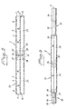
- Figure 1 shows a first embodiment of a reel shaft in accordance with the invention.
- FIG. 2 shows a second embodiment of a reel shaft in accordance with the invention, which reel shaft comprises reinforcement members.
- FIG. 3 shows a third embodiment of a reel shaft in accordance with the invention, which reel shaft exhibits holes passing through it.
- FIG. 4 shows a fourth embodiment of a reel shaft in accordance with the invention, which reel shaft comprises reinforcement members with bar grooves or splines.
- FIG. 5 shows a fifth embodiment of a reel shaft in accordance with the invention, which reel shaft comprises two sleeve parts.
- Figure 6 shows the reel shaft from Figure 5 with connected engagement members.
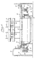
- Figures 7-9 show, schematically, in three orthogonal views, a reel-up for reeling paper onto reel shafts in accordance with the invention.
- Figure 1 shows a first embodiment of a reel shaft 1 in accordance with the invention. Only one of the ends of the reel shaft 1 is shown in Figure 1. However, the other end of the reel shaft 1, not illustrated, is identical to the first, shown end, unless otherwise specified. For this reason the following description refers to the shown end only. This also applies to the subsequent Figures 2-4.
- the reel shaft 1, here shown in its simplest form, comprises a hollow, tubular sleeve 2 that is axially symmetrical about the axis of rotation 3 of the reel shaft 1.
- the sleeve 2 has an envelope surface 4, on which the initial wrapping of:a paper web is intended to be performed during reeling in a reel-up, and also an internal surface 5, which in its axial direction defines a channel 6 running axially through the sleeve 2 and terminating in an axial opening 7 at each end of the sleeve 2.
- the internal surface 5 of the sleeve 2 exhibits a surface portion 8 at each end of the sleeve 2.
- the axial openings 7 of the sleeve 2 Prior to a reeling sequence, are intended to receive two opposing engagement members 32, 33 (see Figure 6) in the reel-up.
- the engagement members 32, 33 are intended to be introduced into the channel 6 of the sleeve 2 to co-operate with and, by means of a locking device, form a detachable engagement with the surface portions 8.
- the engagement members 32, 33 at both ends of the reel shaft 1 are arranged to be extracted from the sleeve 2.
- the sleeve 2 and the paper reeled onto the sleeve 2 thus form a finished paper roll and the sleeve 2 accompanies the paper roll to subsequent processing procedures.
- the sleeve 2 is self-supporting, that is to say that no spindle or axial support element is intended to be introduced into the sleeve 2 to support the same during reeling. Accordingly, the sleeve 2 itself must satisfy the strength criteria made on a reel shaft.
- the sleeve 2 consists mainly of fibre-reinforced plastic, that is a fibre material impregnated with a suitable plastic material.
- the fibres in the fibre-reinforced plastic consist of carbon, aramid, or glass fibres, wound onto an arbor, and the plastic consists of thermo-setting plastic, which is caused to impregnate the fibres wound onto the arbor during the manufacture of the sleeve 2 and thereafter to harden.
- the strength properties of the sleeve 2 for instance the modulus of elasticity of the sleeve 2 can be controlled in that two consecutive winding turns of fibres are wound at. respectively disparate angles.
- the plastic composite configuration of the sleeve 2 entails that the reel shaft 1 exhibits a strength that is on a par with a conventional reel shaft comprising a steel reel spool. The reel shaft 1 is much lighter, however.
- a 5.5 m long reel shaft in accordance with the invention can weigh as little as 800 kg, whereas a corresponding conventional reel shaft comprising a steel reel spool weighs approximately 3100 kg.
- the length of the reel shaft 1 corresponds suitably to the machine width of the paper machine in which the reel shaft 1 is intended to be used, which length is usually in the range 2-8 m.
- the diameter of the sleeve 2 is preferably in the range 310-800 mm and the material thickness of the sleeve 2 in the range 15-36 mm.
- FIG. 2 shows a second embodiment of a reel shaft 9 in accordance with the invention, which reel shaft 9 is especially suitable for use when a relatively brittle fibre material, such as carbon fibres, is used in the sleeve 2.
- the reel shaft 9 comprises two reinforcement members. 10, arranged one at each end of the sleeve 2 to co-operate with said engagement members 32, 33.
- Each reinforcement member 10 has the shape of a rotationally symmetrical, tubular, metal ring that is concentric with the sleeve 2.
- the metal ring 10 has an inner portion 11, penetrating into the sleeve 2 to form a rigid joint with the same, and also an outer portion 12, protruding from the end of the sleeve 2.
- the inner portion 11 has an external surface 14, contacting the surface portion 8 of the sleeve 2 and rigidly joined to the same.
- the metal ring 10 has an internal surface 15, defining a channel 16 that runs axially through the metal ring 10, which channel 16 communicates with the channel 6 of the sleeve 2.
- the engagement members 32, 33 of the reel-up are intended to be introduced into the channels 16 of the metal rings 10 to co-operate with and, by means of a locking device, form a detachable joint with the internal surfaces 15 of the metal rings 10, whereby the sleeve 2 is protected against wear and tear.
- FIG 3 shows a third embodiment of a reel shaft 17 in accordance with the invention.
- the reel shaft 17 is in all respects identical to the reel shaft 1 in Figure 1, save that the envelope surface 4 of the sleeve 2 in this case exhibits a plurality of holes 18 passing through it.
- a negative pressure is created inside at least a part of the reel shaft 17 by means of air being drawn out from the sleeve 2 in a way that will be further described in the following in connection with Figures 6-9.
- air is drawn in through the holes 18 and the paper web is attached to the envelope surface 4 of the sleeve 2 by suction.
- the disposition of the holes 18 must be considered so that the reel shaft 17 is not unbalanced. It is important that the holes 18 are evenly distributed across the envelope surface 4 in the rotational direction of the reel shaft 17.
- the holes 18 are arranged in rows in the longitudinal direction of the sleeve 2, whereby the sleeve 2 exhibits recurring rows of holes in its rotational direction with intervening envelope-surface parts free of holes. Shown in the drawing, is a hole configuration that has proved to be especially effective, in which the holes are arranged in four rows 19, of which only three are illustrated in Figure 4.
- the rows 19 of holes extend along the entire length of the sleeve and are substantially parallel to the axis of rotation 3 of the reel shaft 17, and in the rotational direction of the sleeve 2, the rows 19 of holes recur every quarter of a turn.
- the holes are arranged in two rows 19 of holes, which extend along the entire length of the sleeve 2, are substantially parallel to the axis of rotation 3 of the reel shaft, and recur every half a turn in the rotational direction of the sleeve.
- the internal surface 5 of the sleeve 2 exhibits a surface portion 8 at each end for co-operating with said engagement members.
- FIG 4 shows a fourth embodiment of a reel shaft 20 in accordance with the invention.
- the reel shaft 20 is in all respects identical to the reel shaft 17 in Figure 3, save that the reel shaft 20 in this case comprises two reinforcement members 21 in the form of metal rings.
- the metal rings 21 are in all respects identical to the metal rings 10 in Figure 2, save that the internal surface 15 of each metal ring 21 exhibits bar grooves or splines 22 for co-operating with said engagement members.
- the engagement members in this case exhibit corresponding external bar grooves or splines.
- FIG. 5 shows a fifth embodiment of a reel shaft 23 in accordance with the invention.
- the sleeve 2 of the reel shaft 23 comprises two identical, hollow and tubular sleeve parts 24, 25 that are axially symmetrical about a common axis of rotation 3, which also forms the axis of rotation of the reel shaft 23.
- the sleeve parts 24, 25 are joined to each other by a connection arrangement 26.
- Each sleeve part 24, 25 has an envelope surface 4 and an internal surface 5, defining an axial channel 6.
- the internal surface 5 of each sleeve part 24, 25 exhibits, at the end facing the other sleeve part 25, 24, a surface portion 27 that co-operates with the connection arrangement 26.
- connection arrangement 26 has the shape of a sleeve that is rotationally symmetrical about the axis of rotation 3 and which has two end portions 28, 29, each of which penetrates into a sleeve part 24, 25, respectively.
- the connection arrangement 26 exhibits an axial channel 30 running through it.
- Each end portion 28, 29 has an external surface 31 that connects to the surface portion 27 of the adjoining sleeve part 24, 25 and forms a joint with the same.
- the joint can be rigid, such as a glue joint, though, preferably, the joint between the connection arrangement 26 and at least one of the sleeve parts 24, 25 is detachable, by means of a suitable locking device (not shown), whereby the sleeve parts 24, 25 can be detached from each other when need be.
- connection arrangement 26 can for instance comprise manually or pneumatically controllable gripping devices that can be removed from and inserted into the end portions 28, 29 in the radial direction to form a detachable friction joint with the opposite surface portions 27.
- the channel 30 of the connection arrangement 26 communicates with the channels 6 of the sleeve parts 24, 25, whereby the reeling shaft 23 exhibits a channel that runs through it axially and terminates in an axial opening 7 at end of the reeling shaft 23.
- the internal surfaces 5 at each axial opening exhibit surface portions 8 for co-operating with said engagement members 32, 33.
- Each sleeve part 24, 25 exhibits in its envelope surface 4 a plurality of holes 18 passing through the same and arranged in two rows, of which only one row 19 is visible in Figure 5.
- the rows 19 of holes extend along the entire length of the sleeve part 24, 25, are substantially parallel to the axis of rotation 3 and recur every half a turn in the rotational direction of the reel shaft 23.
- the two sleeve parts 24, 25 are arranged in relation to each other so that the rows 19 of holes in the sleeve part 24 are aligned with the rows 19 of holes in the sleeve part 25.
- each engagement member 32, 33 comprises a first part 34 and a second part 35, telescopically retractable into the first part.
- the engagement members 32, 33 can assume a first position, in which the second parts 35 of the engagement members 32, 33 are retracted inside the first parts 34 and in which the engagement members 32, 33 do not co-operate with the reel shaft 23, and also a second position, in which the second parts 35 of the engagement members 32, 33 project from the first parts 34 and in which the engagement members 32, 33 co-operate with the reel shaft 23.
- the second parts 35 of the engagement members 32, 33 have an engagement portion 36 that is arranged to be inserted into the ends of the reel shaft 23 to co-operate with the surface portions 8 (see Figure 5) and to form a detachable engagement with the same.
- the engagement portions 36 comprise appropriate locking devices (not shown) in the form of pneumatically controllable gripping devices that can be removed from and inserted into the engagement portions 36 in the radial direction to form a detachable friction joint with the opposite surface portions 8.
- the engagement member 33 exhibits a channel 37 that runs axially through it and communicates with the channel 6 of the sleeve part 24 and also with the channel 6 of the sleeve part 25, via the channel 30 of the connection arrangement 26.
- the engagement member 32 has no channel running through it and the axial opening 7 of the sleeve part 25 is thus closed by the engagement portion 36 of the engagement member 32.
- the first part 34 of the engagement member 33 exhibits a recess 38 in the form of a truncated cone.
- the recess 38 is arranged to receive a nozzle that is connected to a vacuum system (see Figures 7-9), whereby air can be extracted from the reel shaft 23 by suction to create a negative pressure inside it.
- a vacuum system see Figures 7-9
- the sleeve parts 24, 25 are manufactured mainly of plastic composite material, thus being lightweight, it is possible to fashion the channel 37 of the engagement member 33 with a cross-sectional area that is relatively large. This prevents the engagement member 33 from becoming an obstacle in the flow path of the air being extracted from the reel shaft 23.
- FIGs 7-9 show, schematically in three orthogonal views, a reel-up in a paper machine in which paper is continuously manufactured in a coherent web 40.
- Figure 7 shows the reel-up from the operator side of the paper machine
- Figure 8 shows the reel-up from above
- Figure 9 shows the reel-up from the downstream end of the paper machine.
- the paper web 40 is continuously reeled onto reel shafts 23 in the reel-up.
- Figures 7-9 these are of the type shown in Figures 5 and 6, but the reel shafts can in principle be any of the other embodiments described above.
- the reel-up comprises two parallel and mirror-inverted, but otherwise identical stand parts 41, 42, extending in the longitudinal direction of the paper machine.
- the first stand part 41 is placed on the operator side of the paper machine, and the other stand part 42 is placed on the drive side of the paper machine.
- the paper machine comprises a support member in the form of a reel drum 43, over which the paper web 40 runs.
- the paper machine further encompasses a wire-turning roll 44, located downstream and below the reel drum 43 and arranged parallel to the same.
- the reel drum 43 and the wire-turning roll 44 are both rotatably journalled on the stand parts 41, 42.
- An endless belt 45 passes over the reel drum 43 and the wire-turning roll 44 and supports the paper web 40, coming from the drying section (not shown) of the paper machine, during its transportation to the reel-up.
- a drive motor (not shown) gives the reel drum 43 a peripheral speed, corresponding to the speed of travel of the belt 45 and, therefore, of the paper web 40.
- the reel drum 43 can be driven by the belt 45, which passes over a plurality of rolls, of which one, for instance the wire-turning roll 44, then is driving.
- said belt is lacking and the paper web passes directly on the reel drum.
- a stock 46 of empty reel shafts 23 is located at the upstream end of the reel-up, above the reel drum 43.
- the stock 46 comprises a substantially horizontal shelf 47, on which the empty reel shafts 23 rest next to each other and parallel to the reel drum 43, waiting to be reeled in the reel-up.
- the reel-up comprises an advancement unit 48 in the form of a carriage, which is mounted on rails 49 to be linearly movable for collecting the empty reeling shafts 23 sequentially from the stock 46 and bringing them to a reeling system for reeling with the aid of lowering arms 50.
- the stock 46 and the advancement unit 48 are removed for the sake of clarity.
- Said reeling system comprises a first movable unit 51 and a mirror-inverted second movable unit 52 in the form of carriages.
- Each carriage 51, 52 comprises two parallel carriage bodies 53, 54, each mounted on one of the stand parts 41, 42, respectively, to be linearly movable in the longitudinal direction of the paper machine.
- the reel-up comprises actuators (not shown), arranged to influence the movement back and forth of the carriages 51, 52 in the longitudinal direction of the paper machine and consisting of, for instance, hydraulic or pneumatic piston cylinders.
- Each carriage body 53, 54 comprises a sledge 55, co-operating with one of the stand parts 41, 42, respectively, and also a pivot unit 57, pivotably mounted about a rotary shaft 56 on the sledge 55.
- each pivot unit 57 can be raised and lowered in relation to its sledge 55 by a pivoting movement about its rotary shaft 56 with the aid of a hydraulic or pneumatic piston cylinder 58.
- the two engagement members 32, 33 described in connection with Figure 6 are rotatably journalled on the pivot units 57 to co-operate and form a detachable engagement with the ends of the reeling shafts 23 in the way described above.
- the reel-up comprises a vacuum system, which here denotes a system for creating a predetermined pressure below normal atmospheric pressure.
- the vacuum system encompasses a first vacuum unit 59, situated on the operator side of the paper machine in the vicinity of the reel drum 43, and a mirror-inverted second vacuum unit 60, situated on the drive side of the paper machine in the vicinity of the reel drum 43.
- Each vacuum unit 59, 60 comprises an air pipe 61, which at one of its ends (not shown) is connected to a vacuum pump or a partial-pressure tank (not shown).
- Each air pipe 61 is, at its other end, connected to a nozzle 62.
- Each nozzle 62 is movably mounted on a stand 67 so that the nozzle 62 can perform a linear movement in the transverse direction of the paper web 40 as well as a movement in the longitudinal direction of the paper machine and a movement in the vertical direction.
- Each engagement member 33 is arranged to receive one of the nozzles 62 at its recess 38 (see Figure 6) in connection with a reeling sequence.
- the first carriage 51 supports a reel shaft 23', which is just about to take over reeling from a reel shaft 23" supported by the second carriage 52, and the engagement member 33 of the first carriage 51 is connected to the nozzle 62 of the first vacuum unit 59 to create a negative pressure in the reel shaft 23'.
- the second vacuum unit 60 is inactive and starts to act only when the second carriage 52 is transported to the reel drum 43 to receive an empty reel shaft 23, the nozzle 62 of the second vacuum unit 60 then being brought into engagement with the engagement means 33 of the second carriage 52.
- each carriage body 53 comprises an auxiliary drive system, that is arranged to drive, i.e. to rotate, the engagement member 32 on the carriage body 53 during a reeling sequence.
- the auxiliary drive system comprises a drive device 63, which can consist of an electric motor rigidly mounted on the carriage body 53 and a drive belt, transmitting the turning torque of the motor to the engagement member 32.
- a reeling sequence encompasses the following.
- the starting position is as shown in Figures 7-9.
- the first carriage 51 has deposited a fully-reeled paper roll 64 onto a transport carriage 65 and is located by the reel drum 43, where it has received an empty reel shaft 23' from the advancement carriage 48.
- a paper roll 66 is in the process of being reeled on the second carriage 52.
- the engagement members 32, 33 on the first carriage 51 are thus connected to the reel shaft 23'.
- the pivot units 57 of the carriage 51 are at this stage in a raised position and the reel shaft 23' is not in contact with the paper web 40.
- the reel shaft 23' situated on the first carriage 51 is caused to rotate at the same speed as the reel drum 43 with the aid of the drive device 63 of the first carriage 51.
- a negative pressure is created inside the reel shaft 23' with the aid of the first vacuum unit 59.
- the reel shaft 23' is moved towards the reel drum 43 by lowering the pivot units 57, after which the paper web 40 is deflected up towards the reel shaft 23', by a stream of air from one or several blow pipes (not shown), arranged below the paper web 40 just downstream of the reel drum 43, whereupon the paper web 40 is attached to the reel shaft 23' by suction and the paper web 40 is wrapped around the reel shaft 23'.
- the contact between the paper web 40 and the paper roll 66 on the second carriage 52 is broken, the reeling of the paper web 40 being transferred to the first carriage 51.
- the now fully reeled paper roll 66 is thereafter transported by the second carriage 52 to an empty transport carriage (not shown), where the paper roll 66 is deposited, whereupon the second carriage 52 is transported upstream to the reel drum 43.
- the advancement unit 48 collects an empty reel shaft 23 from the stock 46 and brings it to the second carriage 52.
- the engagement members 32, 33 of the second carriage 52 are thereafter introduced into the end of the empty reel shaft, whereupon the lowering arms 50 of the advancement unit 48 release the reel shaft, which reel shaft at this stage is ready to be accelerated by the drive device 63 of the second carriage 52, connected to the second vacuum unit 60 and lowered towards the paper web 40 to take over the reeling from the reel shaft 23' when this is full.
- a reel shaft of the type shown in Figure 5 can comprise three or more sleeve parts.
- Such a segmented reel shaft is especially favourable in cases where the paper web is divided in its longitudinal direction during reeling.
- the detaching can be performed by introducing an elongate instrument into one of the axial openings of the reel shaft to release said gripping devices, for instance.
- connection arrangement 26 described in connection with Figure 5 exhibits a channel 30 running axially through the same.
- connection arrangement can comprise a dividing wall, separating the channels 6 of the sleeve parts 24, 25. In certain situations this can be favourable since in such a case it is easier to achieve a substantial negative pressure in the part or parts to which the vacuum system is connected.
Landscapes
- Winding Of Webs (AREA)
- Storage Of Web-Like Or Filamentary Materials (AREA)
- Replacement Of Web Rolls (AREA)
- Sanitary Thin Papers (AREA)
Claims (12)
- Aufrollerwelle (1, 9, 17, 20, 23) für ein Aufrollen einer Papierbahn (40) bei einem Aufroller bei einer Papiermaschine, wobei der Aufroller zumindest eine Einheit (51, 52) hat, die in der Längsrichtung der Papiermaschine beweglich ist und ein Paar an entgegengesetzten Eingriffselementen (32, 33) stützt, wobei jedes von ihnen einen Eingriffsteil (36) hat, wobei die Eingriffsteile (36) so angeordnet sind, dass sie während des Aufrollens die Aufrollerwelle (1, 9, 17, 20, 23) drehbar tragen und lösbar in Eingriff halten,
dadurch gekennzeichnet, dass
die Aufrollerwelle (1, 9, 17, 20, 23) frei von einer Stützwelle ist und eine selbst stützende röhrenartige Hülse (2) hat, die im Wesentlichen aus faserverstärktem Kunststoff besteht, wobei die Hülse (2) eine Mantelfläche (4), an der das Anfangswickeln der Papierbahn (40) ausgeführt werden soll, und außerdem eine Innenfläche (5) hat, die einen axialen Kanal (6) in der Hülse (2) definiert, der bei axialen Öffnungen (7) an den Enden der Aufrollerwelle (1, 9, 17, 20, 23) endet, wobei die Aufrollerwelle (1, 9, 17, 20, 23) so eingerichtet ist, dass sie die Eingriffsteile (36) in den axialen Öffnungen (7) aufnimmt, um das Ausbilden des lösbaren Eingriffs zu ermöglichen. - Aufrollerwelle (1, 17, 23) gemäß Anspruch 1,
dadurch gekennzeichnet, dass
die Innenfläche (5) der Hülse (2) an jedem Ende der Aufrollerwelle (1, 17, 23) einen Flächenabschnitt (8) für ein Zusammenwirken mit den Eingriffsteilen (36) hat. - Aufrollerwelle (9, 20) gemäß Anspruch 1,
dadurch gekennzeichnet, dass
die Innenfläche (5) der Hülse (2) an jedem Ende der Aufrollerwelle (9, 20) einen Oberflächenabschnitt (8) hat und
die Aufrollerwelle (9, 20) an jedem ihrer Enden ein röhrenartiges Verstärkungselement (10, 21) hat, das einen inneren Abschnitt (11) hat, der in die Hülse (2) eingeführt wird, und eine Außenfläche (14), die steif mit dem Flächenabschnitt (8) der Hülse (2) verbunden ist, und auch eine Innenfläche (15) für ein Zusammenwirken mit den Eingriffsteilen (36) aufzeigt. - Aufrollerwelle (20, 23) gemäß einem der Ansprüche 1 - 3,
dadurch gekennzeichnet, dass
die Hülse (2) in ihrer Mantelfläche (4) eine Vielzahl an hindurch laufenden Löchern (18) aufzeigt, die über einen Kanal (37) axial durch zumindest eines der Eingriffselemente (33) laufen, dazu gebracht werden kann, dass sie mit einem Unterdrucksystem in Verbindung gelangt, um einen Unterdruck innerhalb von zumindest einem Teil der Aufrollerwelle (20, 23) zu erzeugen, um Luft durch die Löcher (18) zu saugen und dadurch die Papierbahn (40) an der Mantelfläche (4) der Hülse (2) während des Wickelns anzubringen. - Aufrollerwelle (20, 23) gemäß Anspruch 4,
dadurch gekennzeichnet, dass
die Löcher (18) in Reihen angeordnet sind, wobei die Reihen (19) parallel zu der Drehachse (3) der Hülse (2) sind und in der Drehrichtung der Hülse (2) gleichmäßig verteilt sind, wobei aufgrund von ihnen die Hülse (2) in ihrer Drehrichtung sich wiederholende Reihen (19) an Löchern aufzeigt, wobei die sich dazwischen befindlichen Mantelflächenabschnitte frei von Löchern sind. - Aufrollerwelle (20) gemäß Anspruch 5,
dadurch gekennzeichnet, dass
die Hülse (2) vier Reihen (19) an Löchern aufzeigt, die sich in der Drehrichtung der Hülse (2) bei jeder Vierteldrehung wiederholen. - Aufrollerwelle (23) gemäß Anspruch 5,
dadurch gekennzeichnet, dass
die Hülse (2) zwei Reihen (19) an Löchern aufzeigt, die sich in der Drehrichtung der Hülse (2) bei jeder halben Drehung wiederholen. - Aufrollerwelle (23) gemäß einem der Ansprüche 1 - 7,
dadurch gekennzeichnet, dass
die Hülse (2) zumindest zwei Hülsenteile (24, 25) hat, die eine gemeinsame Drehachse (3) haben und miteinander mittels eines Verbindungsaufbaus (26) verbunden sind. - Aufrollerwelle (23) gemäß Anspruch 8,
dadurch gekennzeichnet, dass
die Hülsenteile (24, 25) lösbar miteinander verbunden sind. - Aufrollerwelle (1, 9, 17, 20, 23) gemäß einem der Ansprüche 1 - 9,
dadurch gekennzeichnet, dass
die Fasern bei dem faserverstärkten Kunststoff aus Kohlenstofffasern, Aramidfasern oder Glasfasern bestehen und der Kunststoff aus thermisch aushärtendem Kunststoff besteht. - Aufrollerwelle bei einer Papiermaschine, bei der Papier fortlaufend bei einer kohärenten Bahn (40) hergestellt wird, die auf Aufrollerwellen (23, 23', 23") bei dem Aufroller gewickelt wird, um Papierrollen (64, 66) auszubilden, bei der die Aufrollerwellen (23) Aufrollkerne bilden, wobei der Aufroller Folgendes aufweistdadurch gekennzeichnet, dassein Lager (46) an leeren Aufrollerwellen (23),eine Vorwärtsbewegungseinheit (48), die so eingerichtet ist, dass sie die leeren Aufrollerwellen (23) aufeinander folgend von dem Lager (46) zu einem Aufrollsystem bewegt, unddas Aufrollsystem mit zumindest einer Einheit (51, 52), die in der Längsrichtung der Papiermaschine beweglich ist und die ein Paar an entgegengesetzten Eingriffelementen (32, 33) stützt, wobei jedes von ihnen einen Eingriffsteil (36) hat, wobei die Eingriffsteile (36) so eingerichtet sind, dass sie die Aufrollerwellen (23', 23") während des Aufrollens drehbar tragen und lösbar in Eingriff bringen,
jede Aufrollerwelle (23, 23', 23") frei von einer Stützwelle ist und eine selbst stützende röhrenartige Hülse (2) hat, die im Wesentlichen aus faserverstärktem Kunststoff besteht, wobei die Hülse (2) eine Mantelfläche (4), an der das anfängliche Umwickeln der Papierbahn (40) ausgeführt werden soll, und außerdem eine Innenfläche (5) hat, die einen axialen Kanal (6) in der Hülse (2) definiert, der bei axialen Öffnungen (7) an den Enden der Aufrollerwelle (23, 23', 23") endet, wobei die Eingriffsteile (36) in der Querrichtung der Papierbahn (40) geradlinig beweglich sind, um in die axialen Öffnungen (7) in Verbindung mit einer Aufrollabfolge geführt zu werden, wobei die Aufrollerwellen (23, 23', 23") so eingerichtet sind, dass sie die Eingriffsteile (36) in ihren axialen Öffnungen (7) aufnehmen, um dass Ausbilden des lösbaren Eingriffs zu ermöglichen. - Aufroller gemäß Anspruch 11,
dadurch gekennzeichnet, dass
die Fasern des faserverstärkten Kunststoffes aus Kohlenstofffasern, Aramidfasern oder Glasfasern bestehen und der Kunststoff aus thermisch aushärtendem Kunststoff besteht.
Applications Claiming Priority (3)
| Application Number | Priority Date | Filing Date | Title |
|---|---|---|---|
| US21450700P | 2000-06-28 | 2000-06-28 | |
| US214507P | 2000-06-28 | ||
| PCT/SE2001/001469 WO2002000539A1 (en) | 2000-06-28 | 2001-06-27 | Reel shaft and reel-up for reeling a paper web |
Publications (2)
| Publication Number | Publication Date |
|---|---|
| EP1294630A1 EP1294630A1 (de) | 2003-03-26 |
| EP1294630B1 true EP1294630B1 (de) | 2004-08-18 |
Family
ID=22799341
Family Applications (1)
| Application Number | Title | Priority Date | Filing Date |
|---|---|---|---|
| EP01944077A Expired - Lifetime EP1294630B1 (de) | 2000-06-28 | 2001-06-27 | Wickelwelle und wickler zum wickeln einer papierbahn |
Country Status (13)
| Country | Link |
|---|---|
| US (5) | US6669818B2 (de) |
| EP (1) | EP1294630B1 (de) |
| JP (1) | JP2004501849A (de) |
| KR (1) | KR20030015299A (de) |
| AT (1) | ATE273905T1 (de) |
| AU (1) | AU2001266518A1 (de) |
| BR (1) | BR0112193B1 (de) |
| CA (1) | CA2411835C (de) |
| DE (1) | DE60105027T2 (de) |
| ES (1) | ES2222379T3 (de) |
| PT (1) | PT1294630E (de) |
| TR (1) | TR200402105T4 (de) |
| WO (1) | WO2002000539A1 (de) |
Families Citing this family (34)
| Publication number | Priority date | Publication date | Assignee | Title |
|---|---|---|---|---|
| US6749723B2 (en) * | 2000-06-28 | 2004-06-15 | Metso Paper Karlstad Ab | Measuring arrangements in a shortened dry end of a tissue machine |
| FI109212B (fi) * | 2000-11-01 | 2002-06-14 | Metso Paper Inc | Järjestely paperikoneen jenkkisylinterin tai vastaavan ja rullaimen yhteydessä |
| DE10119460B4 (de) * | 2001-04-17 | 2004-09-16 | Sca Hygiene Products Gmbh | Verfahren und Vorrichtung zum Aufwickeln einer Materialbahn auf eine als Wickelkern dienende Hülse |
| US7001487B2 (en) * | 2001-12-19 | 2006-02-21 | Kimberly-Clark Worldwide, Inc. | Method and apparatus for transporting a sheet from a dryer to a reel |
| US6797115B2 (en) * | 2002-03-29 | 2004-09-28 | Metso Paper Karlstad Ab | Method and apparatus for making a creped tissue with improved tactile qualities while improving handling of the web |
| DE10240375A1 (de) * | 2002-09-02 | 2004-03-18 | Aurnhammer + Benedict Gmbh + Co. Kg | Materialspender |
| US7494563B2 (en) * | 2002-10-07 | 2009-02-24 | Georgia-Pacific Consumer Products Lp | Fabric creped absorbent sheet with variable local basis weight |
| US8911592B2 (en) | 2002-10-07 | 2014-12-16 | Georgia-Pacific Consumer Products Lp | Multi-ply absorbent sheet of cellulosic fibers |
| US6695245B1 (en) * | 2002-12-13 | 2004-02-24 | Kimberly-Clark Worldwide, Inc. | Turn-up apparatus and method |
| DE10326304A1 (de) * | 2003-06-11 | 2005-02-03 | Voith Fabrics Patent Gmbh | Verfahren und Vorrichtung zur Herstellung einer Tissuebahn |
| FI114648B (fi) * | 2003-06-18 | 2004-11-30 | Metso Paper Inc | Menetelmä ja laitteisto paperi- tai kartonkirainan kalanteroimiseksi |
| FI117429B (fi) * | 2003-09-15 | 2006-10-13 | Metso Paper Inc | Menetelmä kiinnirullaimessa ja kiinnirullain |
| DE202004005645U1 (de) * | 2004-04-08 | 2004-06-09 | Koenig & Bauer Ag | Materialrollen und Offset-Rotationsdruckmaschine |
| AT413393B (de) * | 2003-12-30 | 2006-02-15 | Andritz Ag Maschf | Vorrichtung zur stabilisierung einer papierbahn |
| US7204451B2 (en) * | 2004-02-25 | 2007-04-17 | Sonoco Development, Inc. | Winding core and associated method |
| AT413709B (de) * | 2004-06-28 | 2006-05-15 | Andritz Ag Maschf | Vorrichtung zum kontinuierlichen trocknen einer faserstoffbahn |
| US20060032272A1 (en) * | 2004-08-10 | 2006-02-16 | Besten, Inc. | Spacer backing winder for use with a supplied work product |
| US20060163420A1 (en) * | 2004-12-06 | 2006-07-27 | Sonoco Development, Inc. | High-stiffness winding core |
| GB2428665A (en) * | 2005-08-04 | 2007-02-07 | Deva Composites Ltd | Fibre-reinforced polymeric winding core |
| DE102005046907A1 (de) * | 2005-09-30 | 2007-04-12 | Voith Patent Gmbh | Verfahren und Vorrichtung zur Herstellung einer Tissuebahn |
| DE102005046903A1 (de) * | 2005-09-30 | 2007-04-05 | Voith Patent Gmbh | Verfahren und Vorrichtung zur Herstellung einer Tissuebahn |
| US7661622B2 (en) | 2005-09-30 | 2010-02-16 | Kimberly-Clark Worldwide, Inc. | Apparatus and method for winding and transporting paper |
| DE202006017029U1 (de) * | 2006-11-08 | 2007-01-04 | Voith Patent Gmbh | Wickelmaschine zum Aufwickeln von aus einer Materialbahn erzeugten Teilmaterialbahn |
| DE102007000630A1 (de) * | 2007-11-06 | 2009-05-07 | Voith Patent Gmbh | Wickelhülsenanordnung für eine Rollenwickeleinrichtung, Wickelhülse und Rollenwickeleinrichtung |
| CN103010856A (zh) * | 2012-12-27 | 2013-04-03 | 苏州弘贸纺织有限公司 | 一种重力式纱线筒 |
| JP6257981B2 (ja) * | 2013-09-24 | 2018-01-10 | 富士通コンポーネント株式会社 | ニアエンド検出装置、プリンタ |
| DE202013105818U1 (de) * | 2013-12-19 | 2014-02-19 | Dietze & Schell Maschinenfabrik Gmbh & Co. Kg | Spulvorrichtung zum Aufspulen zumindest eines Wickelguts auf zumindest eine wechselbare Hülse |
| US9809417B2 (en) * | 2015-08-14 | 2017-11-07 | The Procter & Gamble Company | Surface winder |
| WO2018044814A1 (en) | 2016-08-31 | 2018-03-08 | Kimberly-Clark Worldwide, Inc. | Web winding device |
| DE102018112053A1 (de) * | 2018-05-18 | 2019-11-21 | TRüTZSCHLER GMBH & CO. KG | Verfahren zur Ermittlung der Trommelbelegung an einer Karde sowie Karde mit einer zugehörigen Steuerung |
| WO2020002111A1 (en) * | 2018-06-25 | 2020-01-02 | Carbo-Link Ag | Anchor sleeve and anchor system |
| CN111735294B (zh) * | 2019-09-23 | 2021-09-24 | 安徽欧斯福科技有限公司 | 一种纺织生产用成衣烘干机 |
| CN113264397A (zh) * | 2021-04-08 | 2021-08-17 | 四川雷得云母有限公司 | 一种具有均匀快速烘干机构的云母纸收卷装置 |
| CN119845986B (zh) * | 2025-02-18 | 2025-09-23 | 浙江瀚森应用材料有限公司 | 一种铝箔纸加工生产用缺陷检测装置及检测方法 |
Family Cites Families (70)
| Publication number | Priority date | Publication date | Assignee | Title |
|---|---|---|---|---|
| US1842889A (en) * | 1928-09-01 | 1932-01-26 | Harrison R Williams | Paper machinery |
| GB623155A (en) * | 1947-04-22 | 1949-05-12 | Dubilier Condenser Co 1925 Ltd | Improvements in or relating to winding apparatus |
| US3657797A (en) | 1967-06-16 | 1972-04-25 | New England Pressed Steel Co | Core assembly method |
| US3586253A (en) * | 1969-02-06 | 1971-06-22 | Beloit Corp | Reel loader for paper machines or the like |
| DE2048414B2 (de) | 1970-10-02 | 1973-08-02 | Agfa Gevaert AG, 5090 Leverkusen | Vorrichtung zur fotoelektrischen abtastung |
| US3743199A (en) * | 1971-09-02 | 1973-07-03 | Beloit Corp | Method and apparatus for reeling web material |
| US3734307A (en) * | 1972-02-17 | 1973-05-22 | Midland Ross Corp | Apparatus for handling rewind rolls |
| US3889892A (en) * | 1973-08-09 | 1975-06-17 | Beloit Corp | Center start surface wind reel with automatic cut-off and transfer |
| US4087319A (en) * | 1976-12-27 | 1978-05-02 | Beloit Corporation | Method of and means for sheet transfer to and embossing at a reeling station |
| US4179330A (en) | 1978-09-05 | 1979-12-18 | Page Robert E | Apparatus for handling web material, and method |
| US4238539A (en) | 1979-05-29 | 1980-12-09 | Celanese Corporation | Fiber reinforced composite shaft with metallic connector sleeves mounted by a knurl interlock |
| US4328930A (en) * | 1980-07-08 | 1982-05-11 | Jiri Kalendovsky | Composite reel and stand for a swimming pool cover |
| US4356059A (en) * | 1981-11-16 | 1982-10-26 | Crown Zellerbach Corporation | High bulk papermaking system |
| DE3216110C2 (de) * | 1982-04-30 | 1987-05-14 | Erwin Kampf Gmbh & Co Maschinenfabrik, 5276 Wiehl | Achswickelmaschine |
| GB8328354D0 (en) | 1983-10-24 | 1983-11-23 | Black Clawson Int | Surface treatment of paper and paperboard |
| US4606381A (en) * | 1984-02-16 | 1986-08-19 | Tsudakoma Kogyo Kabushiki Kaisha | Method and apparatus for automatically exchanging cloth rollers in a loom |
| FI69438C (fi) * | 1984-07-10 | 1986-02-10 | Waertsilae Oy Ab | Upprullningsanordning |
| FI75542C (fi) * | 1986-02-27 | 1989-09-11 | Ahlstroem Valmet | Anordning foer foerflyttning av tambourvals till en pappers- eller kartongmaskins rullmaskin. |
| FI81768C (fi) | 1987-05-20 | 1990-12-10 | Valmet Paper Machinery Inc | Foerfarande och anordning vid rullning av papper. |
| FI81770C (fi) | 1987-05-20 | 1990-12-10 | Valmet Paper Machinery Inc | Foerfarande vid styrning av pappers rullstol. |
| JP2559444B2 (ja) * | 1988-02-04 | 1996-12-04 | 武田薬品工業株式会社 | シート状成形材料の巻取装置 |
| JP2558495B2 (ja) * | 1988-04-16 | 1996-11-27 | 株式会社イソワ | ウェブ供給装置の制御方法 |
| DE3843246C1 (de) | 1988-12-22 | 1990-05-23 | J.M. Voith Gmbh, 7920 Heidenheim, De | |
| US4969588A (en) * | 1989-06-20 | 1990-11-13 | Baker Burle E | Adjustable reel threader for partially finished logs of differing diameters |
| DE4010894C2 (de) * | 1990-04-04 | 1996-11-28 | Fmc Corp | Revolverkopfaufwickel-Vorrichtung zum Aufwickeln von Bahnmaterial, insbesondere von aus Kunststoffolien bestehenden, in Bandform zusammenhängenden Beuteln |
| WO1991018813A1 (de) | 1990-06-08 | 1991-12-12 | Beloit Corporation | Aufwickelvorrichtung für rollenschneidemaschinen des stützwalzentyps od. dgl. |
| US5269883A (en) * | 1990-08-31 | 1993-12-14 | Kimberly-Clark Corporation | Method for controlling basis weight in the production of stretchable webs |
| US5026458A (en) | 1990-08-31 | 1991-06-25 | Kimberly-Clark Corporation | Method for controlling basis weight in the production of stretchable webs |
| FI91383C (fi) * | 1990-10-26 | 1997-01-22 | Valmet Paper Machinery Inc | Menetelmä kiinnirullauksessa |
| US5150850A (en) | 1991-05-10 | 1992-09-29 | Beloit Corporation | Method for winding a traveling web on a belted two drum wound web roll winder |
| US5308008A (en) | 1992-03-18 | 1994-05-03 | Rueegg Anton | Method and apparatus for producing rolls |
| DE4226789A1 (de) * | 1992-08-13 | 1994-02-17 | Sigri Great Lakes Carbon Gmbh | Faserverstärkte Kunststoffwalze mit äußerer, verschleißfester, füllerhaltiger Kunststoffschicht |
| US5400707A (en) | 1992-10-09 | 1995-03-28 | Champion International Corporation | Apparatus for finishing a continuous sheet of paper |
| US5379964A (en) * | 1993-08-10 | 1995-01-10 | Addax, Inc. | Composite expandable shaft |
| US5377428A (en) | 1993-09-14 | 1995-01-03 | James River Corporation Of Virginia | Temperature sensing dryer profile control |
| FI100467B (fi) * | 1994-05-26 | 1997-12-15 | Valmet Corp | Menetelmä ja laite rainan rullauksessa |
| US5544841A (en) | 1994-08-18 | 1996-08-13 | Beloit Technologies, Inc. | Method and apparatus for reeling a traveling web into a wound web roll |
| US5593545A (en) * | 1995-02-06 | 1997-01-14 | Kimberly-Clark Corporation | Method for making uncreped throughdried tissue products without an open draw |
| WO1996037429A1 (de) | 1995-05-24 | 1996-11-28 | Voith Sulzer Papiermaschinen Gmbh | Wickelvorrichtung zum aufwickeln einer papierbahn |
| EP0747314B1 (de) * | 1995-06-07 | 1999-08-25 | Eastman Kodak Company | Hülse zum Aufwickeln von bahnförmigem, verformbahrem Material |
| SE504708C2 (sv) * | 1995-09-13 | 1997-04-07 | Valmet Karlstad Ab | Sätt och anordning för överföring av en snabbt löpande färdigtorkad fiberbana, särskilt en tissuebana, från en anordning och längs en förutbestämd bana till en efterföljande anordning |
| US5810281A (en) * | 1995-11-20 | 1998-09-22 | Kole; John W. | Spool assembly with slotted tubes |
| US5673870A (en) * | 1995-12-19 | 1997-10-07 | Beloit Technologies, Inc. | Method and apparatus for reeling a traveling paper web |
| US5967457A (en) * | 1996-07-23 | 1999-10-19 | Thermo Wisconsin, Inc. | Airfoil web stabilization and turning apparatus and method |
| DE19635216A1 (de) | 1996-08-30 | 1998-03-05 | Voith Sulzer Papiermasch Gmbh | Verfahren und Vorrichtung zum Aufwickeln einer Papierbahn zu einer Rolle |
| FI106248B (fi) | 1997-02-13 | 2000-12-29 | Valmet Corp | Kiinnirullain ja menetelmä paperirainan tai vastaavan kiinnirullauksessa |
| US6076281A (en) * | 1997-03-03 | 2000-06-20 | Valmet Corporation | Web finishing section in a paper machine |
| DE19748995A1 (de) * | 1997-11-06 | 1999-05-12 | Voith Sulzer Papiertech Patent | Verfahren und Wickelmaschine zum kontinuierlichen Aufwickeln einer Materialbahn |
| ATE234254T1 (de) | 1997-05-16 | 2003-03-15 | Voith Paper Patent Gmbh | Verfahren und wickelmaschine zum kontinuierlichen aufwickeln einer materialbahn |
| DE19727325C2 (de) * | 1997-06-27 | 2003-08-28 | Voith Paper Patent Gmbh | Wickeleinrichtung für eine Materialbahn, insbesondere für eine Rollenschneidvorrichtung |
| US5944273A (en) * | 1997-07-03 | 1999-08-31 | Kimberly-Clark Worldwide, Inc. | Parent roll for tissue paper |
| US5891309A (en) * | 1997-08-26 | 1999-04-06 | Beloit Technologies, Inc. | Web stabilizing device |
| US5931406A (en) | 1997-12-08 | 1999-08-03 | Voith Sulzer Papiertechnik Patent Gmbh | Method and winder for the continuous winding of a material web |
| DE19803137C1 (de) | 1998-01-28 | 1999-06-10 | Voith Sulzer Papiertech Patent | Rollenwickler |
| FI106446B (fi) * | 1998-02-04 | 2001-02-15 | Valmet Corp | Menetelmä rainan rullauksessa |
| FI104161B (fi) * | 1998-02-17 | 1999-11-30 | Valmet Corp | Menetelmä ja laitteisto rainan rullauksessa |
| DE19809516B4 (de) * | 1998-03-05 | 2004-04-15 | Daimlerchrysler Ag | Vorrichtung und Verfahren zum automatischen Wechseln von Folienrollen |
| FI110259B (fi) * | 1998-05-07 | 2002-12-31 | Metso Paper Inc | Menetelmä ja laite rullan kuormittamiseksi rainan rullaimessa |
| US6183601B1 (en) * | 1999-02-03 | 2001-02-06 | Kimberly-Clark Worldwide, Inc. | Method of calendering a sheet material web carried by a fabric |
| IT1307874B1 (it) * | 1999-05-11 | 2001-11-19 | Perini Fabio Spa | Metodo e dispositivo per la produzione di rotoli di materialenastriforme senza anima di avvolgimento. |
| US6398909B1 (en) * | 1999-06-17 | 2002-06-04 | Valmet-Karlstad Aktiebolag | Method and apparatus for imprinting, drying, and reeling a fibrous web |
| FI106484B (fi) | 1999-07-15 | 2001-02-15 | Neles Paper Automation Oy | Sovitelma liikkuvan paperirainan ominaisuuksien mittaamiseksi |
| US6398916B1 (en) * | 1999-12-16 | 2002-06-04 | Valmet Karlstad Ab | Simplified through-air drying paper making machine having a twin wire forming section |
| US6447640B1 (en) * | 2000-04-24 | 2002-09-10 | Georgia-Pacific Corporation | Impingement air dry process for making absorbent sheet |
| FI115062B (fi) * | 2000-07-10 | 2005-02-28 | Metso Paper Inc | Menetelmä tissuepaperin kalanteroimiseksi |
| FI112931B (fi) | 2000-12-07 | 2004-02-13 | Metso Paper Inc | Menetelmä ja laite paperi- tai kartonkirainan rullauksessa |
| US6716308B2 (en) * | 2000-12-14 | 2004-04-06 | Kimberly-Clark Worldwide, Inc. | Method for calendering an uncreped throughdried tissue sheet |
| US6709549B2 (en) * | 2001-03-29 | 2004-03-23 | Metso Paper Karlstad Ab | Multi-reel apparatus in a paper machine |
| US6729572B2 (en) * | 2001-10-31 | 2004-05-04 | Kimberly-Clark Worldwide, Inc. | Mandrelless center/surface rewinder and winder |
| US6652273B2 (en) * | 2002-01-14 | 2003-11-25 | The Procter & Gamble Company | Apparatus and method for controlling the temperature of manufacturing equipment |
-
2001
- 2001-06-15 US US09/882,659 patent/US6669818B2/en not_active Expired - Fee Related
- 2001-06-27 CA CA002411835A patent/CA2411835C/en not_active Expired - Fee Related
- 2001-06-27 DE DE60105027T patent/DE60105027T2/de not_active Expired - Lifetime
- 2001-06-27 ES ES01944077T patent/ES2222379T3/es not_active Expired - Lifetime
- 2001-06-27 TR TR2004/02105T patent/TR200402105T4/xx unknown
- 2001-06-27 AT AT01944077T patent/ATE273905T1/de active
- 2001-06-27 JP JP2002505295A patent/JP2004501849A/ja active Pending
- 2001-06-27 EP EP01944077A patent/EP1294630B1/de not_active Expired - Lifetime
- 2001-06-27 AU AU2001266518A patent/AU2001266518A1/en not_active Abandoned
- 2001-06-27 PT PT01944077T patent/PT1294630E/pt unknown
- 2001-06-27 BR BRPI0112193-6A patent/BR0112193B1/pt not_active IP Right Cessation
- 2001-06-27 KR KR1020027017933A patent/KR20030015299A/ko not_active Withdrawn
- 2001-06-27 WO PCT/SE2001/001469 patent/WO2002000539A1/en not_active Ceased
-
2002
- 2002-12-27 US US10/331,112 patent/US7503520B2/en not_active Expired - Fee Related
-
2003
- 2003-10-10 US US10/683,243 patent/US7192506B2/en not_active Expired - Fee Related
- 2003-10-10 US US10/683,219 patent/US7294232B2/en not_active Expired - Fee Related
- 2003-10-10 US US10/683,790 patent/US7169259B2/en not_active Expired - Fee Related
Also Published As
| Publication number | Publication date |
|---|---|
| US20030141403A1 (en) | 2003-07-31 |
| KR20030015299A (ko) | 2003-02-20 |
| US20040074617A1 (en) | 2004-04-22 |
| ATE273905T1 (de) | 2004-09-15 |
| BR0112193A (pt) | 2003-05-13 |
| JP2004501849A (ja) | 2004-01-22 |
| US20040074619A1 (en) | 2004-04-22 |
| TR200402105T4 (tr) | 2004-09-21 |
| ES2222379T3 (es) | 2005-02-01 |
| BR0112193B1 (pt) | 2010-08-24 |
| US6669818B2 (en) | 2003-12-30 |
| US7503520B2 (en) | 2009-03-17 |
| WO2002000539A1 (en) | 2002-01-03 |
| US20020060036A1 (en) | 2002-05-23 |
| CA2411835C (en) | 2009-04-14 |
| US20040074618A1 (en) | 2004-04-22 |
| CA2411835A1 (en) | 2002-01-03 |
| US7294232B2 (en) | 2007-11-13 |
| EP1294630A1 (de) | 2003-03-26 |
| US7169259B2 (en) | 2007-01-30 |
| US7192506B2 (en) | 2007-03-20 |
| DE60105027D1 (de) | 2004-09-23 |
| AU2001266518A1 (en) | 2002-01-08 |
| PT1294630E (pt) | 2004-11-30 |
| DE60105027T2 (de) | 2005-08-18 |
Similar Documents
| Publication | Publication Date | Title |
|---|---|---|
| CA2411835C (en) | Reel shaft and reel-up for reeling a paper web | |
| FI121007B (fi) | Menetelmä ja järjestely kuiturainan aukirullaimen yhteydessä | |
| FI85362B (fi) | Anordning foer behandling av tryckalster saosom tidningar, tidsskrifter och liknande. | |
| CA1321181C (en) | Method and apparatus for winding a web | |
| EP0943569A2 (de) | Wickelmaschine | |
| EP1514820B1 (de) | Wickelvorrichtung für rollenschneider | |
| CN100595117C (zh) | 卷筒更换装置和实施快速更换卷筒的方法 | |
| EP3498643B1 (de) | Kernspannsystem | |
| WO2009048407A1 (en) | Method and arrangement in rolling-off and rolling-on a web of material | |
| US6086969A (en) | Cylindrical rotating body of low inertia | |
| JPS62126066A (ja) | 巻取装置 | |
| JP3310640B2 (ja) | 巻取装置 | |
| US7896283B2 (en) | Apparatus for winding up at least two material webs | |
| FI107248B (fi) | Paperirainan rullain, rullaimen tela ja menetelmä rullaimessa | |
| FI81315B (fi) | Anordning och foerfarande foer omslagning av rullar av tryckkaensligt banmaterial. | |
| US3718303A (en) | Turnstile-type coil-gathering machine | |
| US2467554A (en) | Shaft winder | |
| CN103930360B (zh) | 卷绕器 | |
| FI110318B (fi) | Menetelmä paperi- tai kartonkirainan rullauksessa ja paperi- tai kartonkirainan rullain | |
| EP2540649B1 (de) | Verfahren und Anordnung in Verbindung mit einem Abwickler | |
| US20070069062A1 (en) | Winding device comprising electrostatic charging means and method for fixing a multi-layered film | |
| CA1041805A (en) | Hose reel for piercer and reeler outlet tables | |
| FI120299B (fi) | Kuiturainan valmistus- ja/tai käsittelylinja | |
| FI107907B (fi) | Menetelmä, laitteisto ja tela paperirainan ohjaamiseksi | |
| KR20190034098A (ko) | 니들 권취 장치 및 니들 권취 방법 |
Legal Events
| Date | Code | Title | Description |
|---|---|---|---|
| PUAI | Public reference made under article 153(3) epc to a published international application that has entered the european phase |
Free format text: ORIGINAL CODE: 0009012 |
|
| 17P | Request for examination filed |
Effective date: 20021220 |
|
| AK | Designated contracting states |
Kind code of ref document: A1 Designated state(s): AT BE CH CY DE DK ES FI FR GB GR IE IT LI LU MC NL PT SE TR |
|
| AX | Request for extension of the european patent |
Extension state: AL LT LV MK RO SI |
|
| RIN1 | Information on inventor provided before grant (corrected) |
Inventor name: GUSTAVSSON, TORD, GUSTAV Inventor name: LINDEN, ANDERS, TOMMY Inventor name: ERIKSSON, SOEREN, SVEN |
|
| GRAP | Despatch of communication of intention to grant a patent |
Free format text: ORIGINAL CODE: EPIDOSNIGR1 |
|
| GRAS | Grant fee paid |
Free format text: ORIGINAL CODE: EPIDOSNIGR3 |
|
| GRAA | (expected) grant |
Free format text: ORIGINAL CODE: 0009210 |
|
| RIN1 | Information on inventor provided before grant (corrected) |
Inventor name: GUSTAVSSON, TORD, GUSTAV Inventor name: ERIKSSON, SOEREN, SVEN Inventor name: LINDEN, ANDERS, TOMMY |
|
| AK | Designated contracting states |
Kind code of ref document: B1 Designated state(s): AT BE CH CY DE DK ES FI FR GB GR IE IT LI LU MC NL PT SE TR |
|
| PG25 | Lapsed in a contracting state [announced via postgrant information from national office to epo] |
Ref country code: BE Free format text: LAPSE BECAUSE OF FAILURE TO SUBMIT A TRANSLATION OF THE DESCRIPTION OR TO PAY THE FEE WITHIN THE PRESCRIBED TIME-LIMIT Effective date: 20040818 Ref country code: LI Free format text: LAPSE BECAUSE OF FAILURE TO SUBMIT A TRANSLATION OF THE DESCRIPTION OR TO PAY THE FEE WITHIN THE PRESCRIBED TIME-LIMIT Effective date: 20040818 Ref country code: CH Free format text: LAPSE BECAUSE OF FAILURE TO SUBMIT A TRANSLATION OF THE DESCRIPTION OR TO PAY THE FEE WITHIN THE PRESCRIBED TIME-LIMIT Effective date: 20040818 |
|
| REG | Reference to a national code |
Ref country code: GB Ref legal event code: FG4D |
|
| REG | Reference to a national code |
Ref country code: CH Ref legal event code: EP |
|
| REG | Reference to a national code |
Ref country code: IE Ref legal event code: FG4D |
|
| REF | Corresponds to: |
Ref document number: 60105027 Country of ref document: DE Date of ref document: 20040923 Kind code of ref document: P |
|
| REG | Reference to a national code |
Ref country code: SE Ref legal event code: TRGR |
|
| PG25 | Lapsed in a contracting state [announced via postgrant information from national office to epo] |
Ref country code: DK Free format text: LAPSE BECAUSE OF FAILURE TO SUBMIT A TRANSLATION OF THE DESCRIPTION OR TO PAY THE FEE WITHIN THE PRESCRIBED TIME-LIMIT Effective date: 20041118 Ref country code: GR Free format text: LAPSE BECAUSE OF FAILURE TO SUBMIT A TRANSLATION OF THE DESCRIPTION OR TO PAY THE FEE WITHIN THE PRESCRIBED TIME-LIMIT Effective date: 20041118 |
|
| REG | Reference to a national code |
Ref country code: PT Ref legal event code: SC4A Free format text: AVAILABILITY OF NATIONAL TRANSLATION Effective date: 20041015 |
|
| LTIE | Lt: invalidation of european patent or patent extension |
Effective date: 20040818 |
|
| REG | Reference to a national code |
Ref country code: ES Ref legal event code: FG2A Ref document number: 2222379 Country of ref document: ES Kind code of ref document: T3 |
|
| REG | Reference to a national code |
Ref country code: CH Ref legal event code: PL |
|
| ET | Fr: translation filed | ||
| PGFP | Annual fee paid to national office [announced via postgrant information from national office to epo] |
Ref country code: NL Payment date: 20050605 Year of fee payment: 5 |
|
| PGFP | Annual fee paid to national office [announced via postgrant information from national office to epo] |
Ref country code: PT Payment date: 20050607 Year of fee payment: 5 |
|
| PGFP | Annual fee paid to national office [announced via postgrant information from national office to epo] |
Ref country code: TR Payment date: 20050623 Year of fee payment: 5 |
|
| PLBE | No opposition filed within time limit |
Free format text: ORIGINAL CODE: 0009261 |
|
| STAA | Information on the status of an ep patent application or granted ep patent |
Free format text: STATUS: NO OPPOSITION FILED WITHIN TIME LIMIT |
|
| PG25 | Lapsed in a contracting state [announced via postgrant information from national office to epo] |
Ref country code: CY Free format text: LAPSE BECAUSE OF FAILURE TO SUBMIT A TRANSLATION OF THE DESCRIPTION OR TO PAY THE FEE WITHIN THE PRESCRIBED TIME-LIMIT Effective date: 20050627 Ref country code: IE Free format text: LAPSE BECAUSE OF NON-PAYMENT OF DUE FEES Effective date: 20050627 Ref country code: LU Free format text: LAPSE BECAUSE OF NON-PAYMENT OF DUE FEES Effective date: 20050627 |
|
| PG25 | Lapsed in a contracting state [announced via postgrant information from national office to epo] |
Ref country code: MC Free format text: LAPSE BECAUSE OF NON-PAYMENT OF DUE FEES Effective date: 20050630 |
|
| 26N | No opposition filed |
Effective date: 20050519 |
|
| REG | Reference to a national code |
Ref country code: IE Ref legal event code: MM4A |
|
| PG25 | Lapsed in a contracting state [announced via postgrant information from national office to epo] |
Ref country code: PT Free format text: LAPSE BECAUSE OF NON-PAYMENT OF DUE FEES Effective date: 20061227 |
|
| PG25 | Lapsed in a contracting state [announced via postgrant information from national office to epo] |
Ref country code: NL Free format text: LAPSE BECAUSE OF NON-PAYMENT OF DUE FEES Effective date: 20070101 |
|
| REG | Reference to a national code |
Ref country code: PT Ref legal event code: MM4A Free format text: LAPSE DUE TO NON-PAYMENT OF FEES Effective date: 20061227 |
|
| NLV4 | Nl: lapsed or anulled due to non-payment of the annual fee |
Effective date: 20070101 |
|
| PGFP | Annual fee paid to national office [announced via postgrant information from national office to epo] |
Ref country code: FI Payment date: 20070615 Year of fee payment: 7 |
|
| PG25 | Lapsed in a contracting state [announced via postgrant information from national office to epo] |
Ref country code: FI Free format text: LAPSE BECAUSE OF NON-PAYMENT OF DUE FEES Effective date: 20080627 |
|
| PG25 | Lapsed in a contracting state [announced via postgrant information from national office to epo] |
Ref country code: TR Free format text: LAPSE BECAUSE OF FAILURE TO SUBMIT A TRANSLATION OF THE DESCRIPTION OR TO PAY THE FEE WITHIN THE PRESCRIBED TIME-LIMIT Effective date: 20040818 |
|
| PGFP | Annual fee paid to national office [announced via postgrant information from national office to epo] |
Ref country code: ES Payment date: 20090709 Year of fee payment: 9 |
|
| PGFP | Annual fee paid to national office [announced via postgrant information from national office to epo] |
Ref country code: GB Payment date: 20090624 Year of fee payment: 9 |
|
| GBPC | Gb: european patent ceased through non-payment of renewal fee |
Effective date: 20100627 |
|
| REG | Reference to a national code |
Ref country code: FR Ref legal event code: ST Effective date: 20110228 |
|
| PG25 | Lapsed in a contracting state [announced via postgrant information from national office to epo] |
Ref country code: FR Free format text: LAPSE BECAUSE OF NON-PAYMENT OF DUE FEES Effective date: 20100630 |
|
| REG | Reference to a national code |
Ref country code: ES Ref legal event code: FD2A Effective date: 20110714 |
|
| PG25 | Lapsed in a contracting state [announced via postgrant information from national office to epo] |
Ref country code: ES Free format text: LAPSE BECAUSE OF NON-PAYMENT OF DUE FEES Effective date: 20110704 Ref country code: GB Free format text: LAPSE BECAUSE OF NON-PAYMENT OF DUE FEES Effective date: 20100627 |
|
| PG25 | Lapsed in a contracting state [announced via postgrant information from national office to epo] |
Ref country code: ES Free format text: LAPSE BECAUSE OF NON-PAYMENT OF DUE FEES Effective date: 20100628 |
|
| PGFP | Annual fee paid to national office [announced via postgrant information from national office to epo] |
Ref country code: FR Payment date: 20090611 Year of fee payment: 9 |
|
| REG | Reference to a national code |
Ref country code: DE Ref legal event code: R082 Ref document number: 60105027 Country of ref document: DE Representative=s name: LORENZ & KOLLEGEN PATENTANWAELTE PARTNERSCHAFT, DE |
|
| REG | Reference to a national code |
Ref country code: DE Ref legal event code: R082 Ref document number: 60105027 Country of ref document: DE Representative=s name: TBK, DE Effective date: 20130709 Ref country code: DE Ref legal event code: R082 Ref document number: 60105027 Country of ref document: DE Representative=s name: TBK, DE Effective date: 20130828 Ref country code: DE Ref legal event code: R081 Ref document number: 60105027 Country of ref document: DE Owner name: METSO PAPER SWEDEN AB, SE Free format text: FORMER OWNER: METSO PAPER KARLSTAD AB, KARLSTAD, SE Effective date: 20130709 Ref country code: DE Ref legal event code: R081 Ref document number: 60105027 Country of ref document: DE Owner name: VALMET AB, SE Free format text: FORMER OWNER: METSO PAPER KARLSTAD AB, KARLSTAD, SE Effective date: 20130709 |
|
| REG | Reference to a national code |
Ref country code: AT Ref legal event code: PC Ref document number: 273905 Country of ref document: AT Kind code of ref document: T Owner name: METSO PAPER SWEDEN AKTIEBOLAG, SE Effective date: 20130918 |
|
| REG | Reference to a national code |
Ref country code: DE Ref legal event code: R082 Ref document number: 60105027 Country of ref document: DE Representative=s name: TBK, DE Effective date: 20140102 Ref country code: DE Ref legal event code: R081 Ref document number: 60105027 Country of ref document: DE Owner name: METSO PAPER SWEDEN AB, SE Free format text: FORMER OWNER: METSO PAPER SWEDEN AB, KARLSTAD, SE Effective date: 20140102 Ref country code: DE Ref legal event code: R081 Ref document number: 60105027 Country of ref document: DE Owner name: VALMET AB, SE Free format text: FORMER OWNER: METSO PAPER SWEDEN AB, KARLSTAD, SE Effective date: 20140102 |
|
| REG | Reference to a national code |
Ref country code: DE Ref legal event code: R082 Ref document number: 60105027 Country of ref document: DE Representative=s name: TBK, DE |
|
| REG | Reference to a national code |
Ref country code: DE Ref legal event code: R081 Ref document number: 60105027 Country of ref document: DE Owner name: VALMET AB, SE Free format text: FORMER OWNER: METSO PAPER SWEDEN AB, SUNDSVALL, SE Effective date: 20140317 Ref country code: DE Ref legal event code: R082 Ref document number: 60105027 Country of ref document: DE Representative=s name: TBK, DE Effective date: 20140317 |
|
| REG | Reference to a national code |
Ref country code: AT Ref legal event code: HC Ref document number: 273905 Country of ref document: AT Kind code of ref document: T Owner name: VALMET AKTIEBOLAG, SE Effective date: 20140612 |
|
| PGFP | Annual fee paid to national office [announced via postgrant information from national office to epo] |
Ref country code: DE Payment date: 20180619 Year of fee payment: 18 |
|
| PGFP | Annual fee paid to national office [announced via postgrant information from national office to epo] |
Ref country code: IT Payment date: 20180620 Year of fee payment: 18 Ref country code: AT Payment date: 20180619 Year of fee payment: 18 |
|
| PGFP | Annual fee paid to national office [announced via postgrant information from national office to epo] |
Ref country code: SE Payment date: 20180618 Year of fee payment: 18 |
|
| REG | Reference to a national code |
Ref country code: DE Ref legal event code: R119 Ref document number: 60105027 Country of ref document: DE |
|
| REG | Reference to a national code |
Ref country code: SE Ref legal event code: EUG |
|
| PG25 | Lapsed in a contracting state [announced via postgrant information from national office to epo] |
Ref country code: SE Free format text: LAPSE BECAUSE OF NON-PAYMENT OF DUE FEES Effective date: 20190628 |
|
| REG | Reference to a national code |
Ref country code: AT Ref legal event code: MM01 Ref document number: 273905 Country of ref document: AT Kind code of ref document: T Effective date: 20190627 |
|
| PG25 | Lapsed in a contracting state [announced via postgrant information from national office to epo] |
Ref country code: DE Free format text: LAPSE BECAUSE OF NON-PAYMENT OF DUE FEES Effective date: 20200101 Ref country code: AT Free format text: LAPSE BECAUSE OF NON-PAYMENT OF DUE FEES Effective date: 20190627 Ref country code: IT Free format text: LAPSE BECAUSE OF NON-PAYMENT OF DUE FEES Effective date: 20190627 |