EP1293877A2 - Datenverarbeitungsapparat - Google Patents
Datenverarbeitungsapparat Download PDFInfo
- Publication number
- EP1293877A2 EP1293877A2 EP02003542A EP02003542A EP1293877A2 EP 1293877 A2 EP1293877 A2 EP 1293877A2 EP 02003542 A EP02003542 A EP 02003542A EP 02003542 A EP02003542 A EP 02003542A EP 1293877 A2 EP1293877 A2 EP 1293877A2
- Authority
- EP
- European Patent Office
- Prior art keywords
- cover unit
- main body
- data processing
- processing apparatus
- cam
- Prior art date
- Legal status (The legal status is an assumption and is not a legal conclusion. Google has not performed a legal analysis and makes no representation as to the accuracy of the status listed.)
- Withdrawn
Links
Images



Classifications
-
- G—PHYSICS
- G06—COMPUTING OR CALCULATING; COUNTING
- G06F—ELECTRIC DIGITAL DATA PROCESSING
- G06F1/00—Details not covered by groups G06F3/00 - G06F13/00 and G06F21/00
- G06F1/16—Constructional details or arrangements
- G06F1/1613—Constructional details or arrangements for portable computers
- G06F1/1615—Constructional details or arrangements for portable computers with several enclosures having relative motions, each enclosure supporting at least one I/O or computing function
- G06F1/1616—Constructional details or arrangements for portable computers with several enclosures having relative motions, each enclosure supporting at least one I/O or computing function with folding flat displays, e.g. laptop computers or notebooks having a clamshell configuration, with body parts pivoting to an open position around an axis parallel to the plane they define in closed position
-
- G—PHYSICS
- G06—COMPUTING OR CALCULATING; COUNTING
- G06F—ELECTRIC DIGITAL DATA PROCESSING
- G06F1/00—Details not covered by groups G06F3/00 - G06F13/00 and G06F21/00
- G06F1/16—Constructional details or arrangements
- G06F1/1613—Constructional details or arrangements for portable computers
- G06F1/1633—Constructional details or arrangements of portable computers not specific to the type of enclosures covered by groups G06F1/1615 - G06F1/1626
- G06F1/1675—Miscellaneous details related to the relative movement between the different enclosures or enclosure parts
- G06F1/1677—Miscellaneous details related to the relative movement between the different enclosures or enclosure parts for detecting open or closed state or particular intermediate positions assumed by movable parts of the enclosure, e.g. detection of display lid position with respect to main body in a laptop, detection of opening of the cover of battery compartment
-
- Y—GENERAL TAGGING OF NEW TECHNOLOGICAL DEVELOPMENTS; GENERAL TAGGING OF CROSS-SECTIONAL TECHNOLOGIES SPANNING OVER SEVERAL SECTIONS OF THE IPC; TECHNICAL SUBJECTS COVERED BY FORMER USPC CROSS-REFERENCE ART COLLECTIONS [XRACs] AND DIGESTS
- Y10—TECHNICAL SUBJECTS COVERED BY FORMER USPC
- Y10S—TECHNICAL SUBJECTS COVERED BY FORMER USPC CROSS-REFERENCE ART COLLECTIONS [XRACs] AND DIGESTS
- Y10S345/00—Computer graphics processing and selective visual display systems
- Y10S345/901—Electronic book with display
-
- Y—GENERAL TAGGING OF NEW TECHNOLOGICAL DEVELOPMENTS; GENERAL TAGGING OF CROSS-SECTIONAL TECHNOLOGIES SPANNING OVER SEVERAL SECTIONS OF THE IPC; TECHNICAL SUBJECTS COVERED BY FORMER USPC CROSS-REFERENCE ART COLLECTIONS [XRACs] AND DIGESTS
- Y10—TECHNICAL SUBJECTS COVERED BY FORMER USPC
- Y10S—TECHNICAL SUBJECTS COVERED BY FORMER USPC CROSS-REFERENCE ART COLLECTIONS [XRACs] AND DIGESTS
- Y10S345/00—Computer graphics processing and selective visual display systems
- Y10S345/905—Display device with housing structure
Definitions
- the present invention relates to a data processing apparatus and particularly to a data processing apparatus equipped with a detecting mechanism for detecting the opening and closing over a main body of a cover that has a display such as an LCD.
- a portable data processing apparatus known as a lap-top computer arranged generally reduced in size and thickness for portable use.
- Such a portable data processing apparatus comprises a main body including a CPU, a set of circuit boards, a keyboard and a cover unit hinged to the main body and having a liquid crystal display or any other display.
- the data processing apparatus As its cover unit is closed to overlap.(mate flush with) the main body, the data processing apparatus is highly portable. When the apparatus is in use, its cover unit is opened to such a position over the main body that the liquid crystal display can be viewed viewed.
- the power supply to the liquid crystal display is automatically disconnected for energy saving of the battery and improvement of the operability.
- the cover unit is opened, the liquid crystal display can automatically be energized.
- the data processing apparatus includes a detecting mechanism for detecting the opening and closing of the cover unit.
- Figs. 1 and 2 illustrate a conventional data processing apparatus 1.
- the data processing apparatus 1 is of a known lap-top type consisting mainly of a main body 2 and a cover unit 3.
- the main body 2 includes a cursor operator, a keyboard, a set of circuit boards (on which a CPU and other controllers are mounted), interfaces, and power sources.
- the cover unit 3 includes a liquid crystal display 8.
- the portable data processing apparatus 1 has the cover unit 3 hinged to the main body 3 so that they are folded closed in the portable mode.
- its cover unit 3 is opened to such a position over the main body 2 that the liquid crystal display 8 can be viewed favorably.
- the data processing apparatus 1 also includes a detecting mechanism 9 for energy saving of the battery and improvement of the operability. This allows the liquid crystal display 8 to be automatically de-energized when the cover unit 3 is closed directly over the main body 2.
- the detecting mechanism 9 comprises an actuator 13 mounted on the cover unit 3 and a detecting switch 10 mounted on the main body 2.
- the actuator 13 extends from the inner wall 3a of the cover unit 3 or more precisely the lowermost part adjacent to the center of turning movement of the inner wall 3a.
- the detecting switch 10 is located with its switching knob 11 in an opening 12 which is provided in a cover member 7 of the main body 2.
- the cover unit 3 When the cover unit 3 is closed, its actuator 13 moves into the opening 12 and presses against the switching knob 11. As a result, the detecting switch 10 is shifted from one of ON and OFF states to the other. Upon receiving an ON or OFF signal from the detecting switch 10, the detecting mechanism 9 detects the opening or closing of the cover unit 3. Accordingly, when the cover unit 3 is opened, the liquid crystal display 8 can automatically be energized. When the cover unit 3 is closed, the liquid crystal display 8 can automatically be de-energized.
- the detecting mechanism 9 in the conventional data processing apparatus 1 prefferably has the opening 12 provided in the cover member 7 of the base unit 2 so that the detecting switch 10 can be manipulated by the actuator 13 through the opening 12.
- the opening 12 may allow dust or dirt to enter the main body 2 and accumulate directly on the electronic components or moving parts thus interrupting the proper action of the electronic components or moving parts. Also, as the actuator 13 is located close to the liquid crystal display 8 which is continuously viewed by the user, it may spoil the appearance of the apparatus.
- the present invention has been developed in view of the foregoing aspects and its object is to provide a data processing apparatus that inhibits any dust or dirt from entering the data processing apparatus while improving its external appearance.
- the present invention offers novel means which are described below.
- a data processing apparatus comprising:
- the cam for actuating the detecting switch is coaxially mounted to the pivot shaft about which the cover unit is rotated in relation to the main body and can thus be turned together with the pivot shaft.
- the detecting switch is actuated by the action of the cam at one end of the pivot shaft, there is no need to provide an opening in the main body nor actuating portion on the inner wall of the cover unit.
- the apparatus can inhibit any dust or dirt from entering the data processing apparatus as well as improving its appearance.
- the data processing apparatus may be modified in that a lever is provided between the cam and the detecting switch for transmitting a displacement of the cam to the detecting switch.
- the lever located between the cam and the detecting switch is arranged to transmit the displacement of the cam to the detecting switch, its design (size, shape, location) can have a degree of freedom.
- the data processing apparatus according to claim 1 may be modified in that a cover member is provided in the main body for covering the detecting mechanism as well as internal components of the main body.
- the detecting mechanism is protected with the cover member, which extends over the internal components in the main body, the number of the components and thus the overall cost of production can be significantly decreased as compared with a conventional arrangement using a separate covering member for protecting the detecting mechanism. Also, as the detecting mechanism is fully protected, it can be free from dust or dirt entering.
- the data processing apparatus may be modified in that the detecting switch is arranged for energizing and de-energizing a display provided on the cover unit.
- FIG. 3 is an enlarged perspective view showing substantially a detecting mechanism 29 in the data processing apparatus 20 (with a cover member 27 removed).
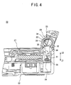
- Fig. 4 is an enlarged cross sectional view showing substantially the detecting mechanism 29 in the data processing apparatus 20.
- Fig. 5 is a perspective view showing an external appearance of the data processing apparatus 20. Throughout the drawings, a cover unit 23 is in its opened state.
- the data processing apparatus 20 of the embodiment is of a known lap-top type.
- the data processing apparatus 20 consists mainly of a main body 22 and the cover unit 23.
- the main unit 22 includes a cursor operator 24, a keyboard 26, a set of circuit boards not shown (a CPU and other controllers), interfaces, and power sources.
- the cover unit 23 includes a liquid crystal display 28 or any other display.
- the cover unit 23 is closed in a direction denoted by the arrow B1 in Fig. 5 so that it overlaps the main body 22 for improvement of the portability.
- its cover unit 23 is opened to such a position in a direction denoted by the arrow B2 in Fig. 5 so that the liquid crystal display 28 is favorably viewed.
- the main body 22 and the cover unit 23 in the embodiment are joined at both ends to each other by a pair of hinges 25. This allows the cover unit 23 to rotate about the hinges 25 in both directions denoted by the arrows B1 and B2 in relation to the main body 22.
- the data processing apparatus 20 of the embodiment has the detecting mechanism 29 arranged for energy saving of the battery and improvement of the operability.
- the detecting mechanism 29 automatically disconnects the liquid crystal display 28 from its power supply when the cover unit 23 is closed over the main body 22 in the portable mode (not in use).
- the detecting mechanism 29 automatically energizes the liquid crystal display 28.
- the detecting mechanism 29 consists mainly of a detecting switch 30, a cam 33, and a lever 35.
- the detecting switch 30 is switched on and off by the action of its switching knob 31 and mounted on a circuit board 39 provided in the main body 22.
- the circuit board 39 has a control circuit provided thereon for energizing and de-energizing the liquid crystal display 28.
- the detecting switch 30 is mounted directly on the circuit board 39, its response can be increased. Also, the detecting switch 30 needs no extra wiring arrangement for connection with the circuit board 39.
- the circuit board 39 of the embodiment is located far away from the front side (the upper end in the drawing) of the main body 22.
- the cam 33 is arranged integral with one end (along a direction denoted by the arrow X1 in Fig. 3) of a pivot shaft 32.
- the cam 33 is coaxial with the axis of pivotal movement of the pivot shaft 32.
- the cam 33 is shaped where its maximum lifting stroke is smaller than the radius of the pivot shaft 32. More specifically, the cam 33 remains radially inward of the outer edge of the pivot shaft 32 when viewed from one side as best shown in Fig. 4.
- the pivot shaft 32 with the cam 33 is arranged for pivotal movement together with the cover unit 23. This allows the cam 33 to turn when the cover unit 23 is moved about the pivot shaft 32. Accordingly, as the cover unit 23 is turned in the direction denoted by the arrow B1 in Fig. 5 for the closing movement, the cam 33 presses downwardly (in a direction denoted by the arrow Z1 in Fig. 4) with its actuating portion 34, where the lifting stroke becomes maximum, against the uppermost end 36 of the lever 35.
- the lever 35 is made of a sheet spring material which is fixedly joined at one end (along a direction denoted by the arrow X2 in Fig. 3) to the main body 22. This allows the lever 35 to be supported in cantilever relationship.
- the lever 35 is arranged of substantially a Z shape including an upper tab portion 36 and a lower tab portion 37.
- the upper tab portion 36 can be directly engaged with the actuating portion 34 of the cam 33.
- the lower tab portion 37 remains engaged with the switching knob 31 of the detecting switch 30.
- the detecting mechanism 29 of the embodiment has the cam 33 mounted coaxially to the end (along the X1 direction) of the pivot shaft 32 for actuating the detecting switch 30.
- the cam 33 is shaped to remain inwardly of the outer radial edge of the pivot shaft 32 when viewed from one side.
- the cover member 27 has a U shaped portion 38 thereof shown in the cross section of Fig 4 for accommodating the cam 33. This allows the main body 22 to be protected from dust or dirt and the data processing apparatus 20 to be improved in the appearance.
- the detecting switch 30 in the embodiment is actuated by the action of the lever 35 but not directly by the cam 33.
- the cam 33 and the detecting switch 30 can be spaced apart from each other. More specifically, both the cam 33 and the detecting switch 30 can be placed with a higher degree of freedom.
- the cam 33 and the detecting switch 30 may need to be placed separate from each other. According to the embodiment, the cam 33 and the detecting switch 30 can be placed with a higher degree of freedom, thus contributing to the reduction in the thickness and size of the data processing apparatus 20. In case that the cam 33 and the detecting switch 30 are to be placed close to each other, the lever member 35 may be eliminated.
- the cover member 27 is used for protecting the cam 33 in the embodiment. It is desirable that the cover member 27 be located close to the cover unit 23 over the main body 22.
- the cover member 27 has the U shaped portion 38 provided for protecting the actuating portion 34 of the cam 33. This can successfully reduce the number of components and thus the overall cost of production as compared with the prior art where the cam 33 (in the detecting mechanism 29) is protected with another extra member in addition the cover member 27. Also, as the cam 33 (in the detecting mechanism 29) is securely protected with the U shaped portion 38, it can be highly dust-proof.
- the present invention is not limited to the embodiment that is described in the form of a laptop personal computer but may be applicable to any type of the data processing apparatus having a cover unit arranged openable in relation to a main body thereof (e.g. a portable DVD player or navigation system).
- the present invention offers the following advantages.
- the detecting switch can be actuated by the action of the cam provided at the axial end of the pivot shaft. This eliminates any need of an opening provided in the main body or an actuating portion provided on the inner wall of the cover unit, thus inhibiting dust or dirt from entering the main body and improving the appearance of the data processing apparatus.
- the detecting switch can be placed with a higher degree of freedom.
- the number of components and the overall cost of production can be decreased significantly as compared with the prior art arrangement where the detecting mechanism is protected with an extra member. Also, as the detecting mechanism is securely protected, it can be free from fouling with dust or dirt.
- the display can be energized and de-energized dependably by the opening and closing action of the cover unit.
Landscapes
- Engineering & Computer Science (AREA)
- Computer Hardware Design (AREA)
- Theoretical Computer Science (AREA)
- Physics & Mathematics (AREA)
- Human Computer Interaction (AREA)
- General Engineering & Computer Science (AREA)
- General Physics & Mathematics (AREA)
- Mathematical Physics (AREA)
- Power Sources (AREA)
- Input From Keyboards Or The Like (AREA)
- Feeding And Guiding Record Carriers (AREA)
- Casings For Electric Apparatus (AREA)
Applications Claiming Priority (2)
| Application Number | Priority Date | Filing Date | Title |
|---|---|---|---|
| JP2001283798 | 2001-09-18 | ||
| JP2001283798A JP2003091332A (ja) | 2001-09-18 | 2001-09-18 | 情報処理装置 |
Publications (2)
| Publication Number | Publication Date |
|---|---|
| EP1293877A2 true EP1293877A2 (de) | 2003-03-19 |
| EP1293877A3 EP1293877A3 (de) | 2004-01-02 |
Family
ID=19107244
Family Applications (1)
| Application Number | Title | Priority Date | Filing Date |
|---|---|---|---|
| EP02003542A Withdrawn EP1293877A3 (de) | 2001-09-18 | 2002-02-15 | Datenverarbeitungsapparat |
Country Status (3)
| Country | Link |
|---|---|
| US (2) | US6906698B2 (de) |
| EP (1) | EP1293877A3 (de) |
| JP (1) | JP2003091332A (de) |
Cited By (3)
| Publication number | Priority date | Publication date | Assignee | Title |
|---|---|---|---|---|
| EP1662775A1 (de) * | 2004-11-25 | 2006-05-31 | Sebastian Grundt | Handlicher Vorschau-Monitor zum Betrachten eines Kamerabildes am Filmset |
| GB2403370B (en) * | 2003-06-17 | 2007-04-25 | Ash Technologies Res Ltd | A viewing device |
| CN101086930B (zh) * | 2006-06-08 | 2010-05-12 | 厦门厦华新技术有限公司 | 车载电视机的液晶屏到位开关 |
Families Citing this family (15)
| Publication number | Priority date | Publication date | Assignee | Title |
|---|---|---|---|---|
| JP3759723B2 (ja) * | 2002-05-16 | 2006-03-29 | 三菱電機株式会社 | 電子機器の仮固定構造 |
| WO2004111810A1 (ja) * | 2003-06-12 | 2004-12-23 | Fujitsu Limited | 開閉検出装置、携帯用コンピュータ、及び電子機器 |
| WO2005017725A1 (ja) * | 2003-08-15 | 2005-02-24 | Fujitsu Limited | スイッチロック装置、携帯用コンピュータ、及び電子機器 |
| CN1764360A (zh) * | 2004-10-20 | 2006-04-26 | 摩托罗拉公司 | 可闭合电子设备 |
| ITMI20060007U1 (it) * | 2006-01-12 | 2007-07-13 | Elesa Spa | Cerniera avente un interruttore di sicurezza incorporato |
| JP2007233505A (ja) * | 2006-02-28 | 2007-09-13 | Toshiba Corp | 情報処理装置および制御方法 |
| TWI366207B (en) * | 2006-06-29 | 2012-06-11 | Teco Image System Co Lted | Control panel and mode-switching device thereof |
| TWM305379U (en) * | 2006-08-11 | 2007-01-21 | Quanta Comp Inc | The elastic sleeping device of notebook |
| JP2010146241A (ja) * | 2008-12-18 | 2010-07-01 | Toshiba Corp | 情報処理装置及びその制御方法 |
| TWM380697U (en) * | 2009-10-20 | 2010-05-11 | Wistron Corp | Switching unit and cover-lifting type electronic device |
| WO2011146064A1 (en) * | 2010-05-20 | 2011-11-24 | Hewlett-Packard Development Company, L.P. | Flow diversion apparatuses and methods |
| US8687361B2 (en) * | 2011-03-11 | 2014-04-01 | Blackberry Limited | Clamshell portable electronic device with input device in hinge |
| JP5797179B2 (ja) * | 2012-10-25 | 2015-10-21 | Necパーソナルコンピュータ株式会社 | 開閉式電子機器 |
| ITMI20130061U1 (it) * | 2013-02-18 | 2014-08-19 | Elesa Spa | Cerniera avente un interruttore di sicurezza incorporato. |
| KR102406557B1 (ko) * | 2015-07-15 | 2022-06-08 | 엘지전자 주식회사 | 키보드 및 이를 구비하는 단말 시스템 |
Family Cites Families (9)
| Publication number | Priority date | Publication date | Assignee | Title |
|---|---|---|---|---|
| JPH066391Y2 (ja) * | 1988-11-30 | 1994-02-16 | 株式会社東芝 | 表示部開閉検出機構 |
| US5592362A (en) * | 1993-10-29 | 1997-01-07 | Kabushiki Kaisha Toshiba | Electronic system having portable electronic apparatus and external expansion unit for expanding function of electronic apparatus |
| JP3676891B2 (ja) * | 1996-10-08 | 2005-07-27 | 富士通株式会社 | 小型携帯用情報処理装置 |
| JPH10187317A (ja) * | 1996-12-26 | 1998-07-14 | Toshiba Corp | コンピュータシステム及び同システムに適用するキーボード制御装置 |
| JPH10268971A (ja) * | 1997-03-25 | 1998-10-09 | Toshiba Corp | 携帯形情報機器 |
| KR100252255B1 (ko) * | 1997-04-15 | 2000-04-15 | 윤종용 | 휴대용 컴퓨터 시스템을 위한 전원 제어 방법 |
| JP4212708B2 (ja) * | 1998-03-16 | 2009-01-21 | 富士通株式会社 | 情報処理装置及び電子機器 |
| US6560103B1 (en) * | 1998-09-22 | 2003-05-06 | Sanyo Electric Co., Ltd. | Accessory of electronic device |
| JP2002281133A (ja) * | 2001-03-15 | 2002-09-27 | Alps Electric Co Ltd | 開閉検出装置 |
-
2001
- 2001-09-18 JP JP2001283798A patent/JP2003091332A/ja active Pending
-
2002
- 2002-02-15 EP EP02003542A patent/EP1293877A3/de not_active Withdrawn
- 2002-02-19 US US10/078,900 patent/US6906698B2/en not_active Expired - Fee Related
-
2005
- 2005-05-20 US US11/134,781 patent/US7352357B2/en not_active Expired - Fee Related
Cited By (3)
| Publication number | Priority date | Publication date | Assignee | Title |
|---|---|---|---|---|
| GB2403370B (en) * | 2003-06-17 | 2007-04-25 | Ash Technologies Res Ltd | A viewing device |
| EP1662775A1 (de) * | 2004-11-25 | 2006-05-31 | Sebastian Grundt | Handlicher Vorschau-Monitor zum Betrachten eines Kamerabildes am Filmset |
| CN101086930B (zh) * | 2006-06-08 | 2010-05-12 | 厦门厦华新技术有限公司 | 车载电视机的液晶屏到位开关 |
Also Published As
| Publication number | Publication date |
|---|---|
| US20050212792A1 (en) | 2005-09-29 |
| US7352357B2 (en) | 2008-04-01 |
| JP2003091332A (ja) | 2003-03-28 |
| EP1293877A3 (de) | 2004-01-02 |
| US6906698B2 (en) | 2005-06-14 |
| US20030052858A1 (en) | 2003-03-20 |
Similar Documents
| Publication | Publication Date | Title |
|---|---|---|
| US6906698B2 (en) | Data processing apparatus | |
| JP4212708B2 (ja) | 情報処理装置及び電子機器 | |
| JP4783470B1 (ja) | 電子機器 | |
| JP4912969B2 (ja) | 電子機器 | |
| GB2318195A (en) | Portable information processing apparatus with automatic orientation of display | |
| EP1380920B1 (de) | Funktionserweiterungsvorrichtung für Informationsverarbeitungsgerät | |
| US5953205A (en) | Portable type information apparatus having a first housing with a display portion and a second housing movable to cover the first housing with a key in one, extending into a recess of the other, of the first and second housings | |
| US20100134966A1 (en) | Information processing apparatus having switch for inputting key data | |
| KR20040020151A (ko) | 휴대 가능한 복합형 컴퓨터의 키보드 탈착 장치 | |
| GB2426870A (en) | Antenna selection system for a mobile device used in various configurations | |
| JP2001117668A (ja) | 携帯用電子機器 | |
| US20090002931A1 (en) | Display device and electronic apparatus | |
| EP0793163B1 (de) | Tragbarer Rechner | |
| US20060203014A1 (en) | Convertible computer system | |
| US20120275099A1 (en) | Portable electronic device | |
| JPH0455580A (ja) | ラッチ装置およびラッチ装置を有する携帯形情報機器 | |
| JP4843740B2 (ja) | 電子機器 | |
| JP2007058580A (ja) | 電子機器 | |
| US12057266B2 (en) | Wheel control mechanism and mouse device with same | |
| JP4843741B2 (ja) | 電子機器 | |
| JP2012009074A (ja) | 電子機器 | |
| US7957629B2 (en) | Image recording/reproducing apparatus | |
| US20250029539A1 (en) | Information processing apparatus and image forming apparatus that perform display control for display device | |
| JP2002132383A (ja) | 電子機器 | |
| JP2009163768A (ja) | 情報処理装置 |
Legal Events
| Date | Code | Title | Description |
|---|---|---|---|
| PUAI | Public reference made under article 153(3) epc to a published international application that has entered the european phase |
Free format text: ORIGINAL CODE: 0009012 |
|
| AK | Designated contracting states |
Kind code of ref document: A2 Designated state(s): AT BE CH CY DE DK ES FI FR GB GR IE IT LI LU MC NL PT SE TR |
|
| AX | Request for extension of the european patent |
Extension state: AL LT LV MK RO SI |
|
| PUAL | Search report despatched |
Free format text: ORIGINAL CODE: 0009013 |
|
| AK | Designated contracting states |
Kind code of ref document: A3 Designated state(s): AT BE CH CY DE DK ES FI FR GB GR IE IT LI LU MC NL PT SE TR |
|
| AX | Request for extension of the european patent |
Extension state: AL LT LV MK RO SI |
|
| 17P | Request for examination filed |
Effective date: 20040628 |
|
| AKX | Designation fees paid |
Designated state(s): DE FR GB |
|
| 17Q | First examination report despatched |
Effective date: 20040824 |
|
| STAA | Information on the status of an ep patent application or granted ep patent |
Free format text: STATUS: THE APPLICATION IS DEEMED TO BE WITHDRAWN |
|
| 18D | Application deemed to be withdrawn |
Effective date: 20110901 |