EP1291982B1 - Fiche pivotable - Google Patents
Fiche pivotable Download PDFInfo
- Publication number
- EP1291982B1 EP1291982B1 EP02450177A EP02450177A EP1291982B1 EP 1291982 B1 EP1291982 B1 EP 1291982B1 EP 02450177 A EP02450177 A EP 02450177A EP 02450177 A EP02450177 A EP 02450177A EP 1291982 B1 EP1291982 B1 EP 1291982B1
- Authority
- EP
- European Patent Office
- Prior art keywords
- plug
- shaped
- rod
- limbs
- limb
- Prior art date
- Legal status (The legal status is an assumption and is not a legal conclusion. Google has not performed a legal analysis and makes no representation as to the accuracy of the status listed.)
- Expired - Lifetime
Links
Images

Classifications
-
- H—ELECTRICITY
- H01—ELECTRIC ELEMENTS
- H01R—ELECTRICALLY-CONDUCTIVE CONNECTIONS; STRUCTURAL ASSOCIATIONS OF A PLURALITY OF MUTUALLY-INSULATED ELECTRICAL CONNECTING ELEMENTS; COUPLING DEVICES; CURRENT COLLECTORS
- H01R24/00—Two-part coupling devices, or either of their cooperating parts, characterised by their overall structure
- H01R24/66—Two-part coupling devices, or either of their cooperating parts, characterised by their overall structure with pins, blades or analogous contacts and secured to apparatus or structure, e.g. to a wall
-
- H—ELECTRICITY
- H01—ELECTRIC ELEMENTS
- H01R—ELECTRICALLY-CONDUCTIVE CONNECTIONS; STRUCTURAL ASSOCIATIONS OF A PLURALITY OF MUTUALLY-INSULATED ELECTRICAL CONNECTING ELEMENTS; COUPLING DEVICES; CURRENT COLLECTORS
- H01R24/00—Two-part coupling devices, or either of their cooperating parts, characterised by their overall structure
- H01R24/58—Contacts spaced along longitudinal axis of engagement
-
- H—ELECTRICITY
- H01—ELECTRIC ELEMENTS
- H01R—ELECTRICALLY-CONDUCTIVE CONNECTIONS; STRUCTURAL ASSOCIATIONS OF A PLURALITY OF MUTUALLY-INSULATED ELECTRICAL CONNECTING ELEMENTS; COUPLING DEVICES; CURRENT COLLECTORS
- H01R35/00—Flexible or turnable line connectors, i.e. the rotation angle being limited
- H01R35/04—Turnable line connectors with limited rotation angle with frictional contact members
-
- H—ELECTRICITY
- H01—ELECTRIC ELEMENTS
- H01R—ELECTRICALLY-CONDUCTIVE CONNECTIONS; STRUCTURAL ASSOCIATIONS OF A PLURALITY OF MUTUALLY-INSULATED ELECTRICAL CONNECTING ELEMENTS; COUPLING DEVICES; CURRENT COLLECTORS
- H01R2103/00—Two poles
Definitions
- the invention relates to a plug, in particular for connecting a musical instrument, a microphone, od.dergl., With an amplifier, a recording device od.dergl. with a central, rod-shaped conductor which carries a mushroom-shaped part at one end, with a shell of electrically conductive material surrounding the rod-shaped conductor at a radial distance, and an insulating material spatially separating the rod-shaped conductor and the shell.
- musical instruments more precisely, their Tonaufnado, connected by means of a cable to the respective amplifier, mixer, recorder or sound processing device.
- the cables have plugs that are plugged into the sockets provided for this purpose.
- the actual plug itself is the same in both cases, so depending on the application situation and desire of the player, a cable with one of the two connectors is used.
- the orientation of the radio with respect to the plug longitudinal axis is a critical size.
- the socket is arranged so that its axis lies in the median plane of the guitar, so the transmitter with respect to the connector should be arranged so that it lies substantially in the continuation of this axis, otherwise there is a risk that the user of the device pulls out of the socket.
- the socket is on the guitar surface and thus the axis is normal to the plane of the guitar, also be arranged substantially normal to the plug axis, not too far over the surface of the guitar to precede and thus hinder the playing of the instrument.
- the plug itself are about the plug axis which coincides in the inserted state, of course, with the socket axis, rotationally symmetrical and therefore rotatable in the plug.
- the structure is such that a rod-shaped, mushroom-shaped at its end, central pin is electrically isolated over most of its axial extent surrounded by a conductive cylindrical shell, but ends at a distance from the mushroom-shaped end. In this way, a two-pole contact is possible and by the mushroom-shaped configuration of a contact and a positive axial fixation of the plug in the socket (resilient tongue, etc.) is possible.
- the object of the invention to provide a connector that makes it possible to dispense with the different designs of transmitters, filters or the like or it allows departing from the connector cables always in the optimal application of the respective case allow.
- this object is achieved in that the rod-shaped, central conductor at its end facing away from the mushroom-shaped end of the plug with a T-shape extending to it cylindrical cross bar, the two stubs have different diameters, is electrically connected, and that of outer sleeve-shaped conductor with the thinner stub at a distance at least partially surrounding and electrically isolated from it held sleeve is electrically conductively connected.
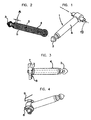
- FIG. 1 shows a connector according to the invention 1.
- This plug consists essentially of an electrically conductive rod-shaped structure 2, at its plug-side end an approximately mushroom-shaped, consisting of electrically conductive material part 3 is fixed, for example by brazing.
- the socket-distal end is approximately T-shaped and rotatable about an axis 13 in an electrical device 10 (FIG. Fig. 5 ) assembled.
- the plug 1 furthermore has a casing 4 made of electrically conductive metal, which is located at the plug-in side at a distance A (FIG. Fig. 2 ) from the mushroom-shaped part 3 ends.
- the area between the shell 4 and the rod-shaped part 2 or the mushroom-shaped part 3 is electrically insulated by casting or encapsulation with an electrically non-conductive material (insulator) 5, so that the two electrically conductive parts are electrically separated from each other.
- a substantially L-shaped contact member 6 is attached, either integrally formed with the shell 4 or soldered to it, electrically bonded glued, or even connected in a different way.
- the leg of the L-shaped contact part 6, which protrudes away from the shell 4, now has no planar shape, but is shaped according to a circular cylindrical surface whose axis of rotation with the axis 13 (FIG. Fig. 1 ) of a bolt 7 with a stepped diameter coincides.
- This pin 7 forms the above-mentioned T-piece on the rod-shaped conductor 2, and the stub with the larger diameter also serves to further contacting the rod-shaped conductor 2.
- the outer surface of the L-shaped contact piece 6 extends concentrically or in alignment with the lateral surface of the stub of the T Pieces with the larger diameter and is mechanically connected by molding with electrically non-conductive material with the stub with a smaller radius, but is exposed with its outer surface, so there can be made contacting the sleeve 4.
- the plug 1 After encapsulation with the electrical insulating material 5, preferably in one step with the encapsulation of the rod-shaped conductor 2, the plug 1 has the in Fig. 1 shown construction and can by means of the two stubs of the T-piece in a corresponding shaped bearing in which it is mechanically held rotatably about its axis 13 and electrically contacted in all permissible positions, are attached.
- the shape and type of contacting and the formation of the tee 7 does not have to be as shown, but can be variously modified: Thus, it is possible to provide the two stubs with different diameters or with different lengths to a proper insertion into the pivot bearing to make sure. It may also be the contact legs of the L-shaped contact piece 6 formed as a sleeve to be contacted over a larger part of the circumference or over the entire circumference electrically.
- a spring around the two stubs of the T-piece and to anchor it in at least one slot at the end of one of the stubs in order to ensure a preferred position of the connector on the device or component to which it is rotatably mounted ,
- This variant is in the FIG. 4 shown.
- Two springs 8, 9 are each associated with one of the stubs and mounted and held at one end in a radial slot on the end face of the stub. The other end protrudes substantially tangentially from the cylindrical stub surface and can be stirred into a corresponding recess in the device in which the plug is rotatably mounted. Between the two ends, the spring is spirally and / or guided along a helical line around the stub and is thus non-positively in each position of the plug and good contacting with its two ends in the corresponding receptacles.
- the Fig. 5 shows, purely schematically in section the installation of a plug according to the invention in a radio device 10:
- An inventively designed plug 1 is pivotally mounted by means of its stub in a bearing 11, wherein it by the in Fig. 5 non-visible springs 8, 9 or other resilient elements is pressed into the position shown.
- the plug 1 can be pivoted against the spring force without great effort in the direction of arrow 12, whereby the position of the radio device 10 with respect to the axis of the socket into which the plug 1 is inserted, can be adapted to the respective needs.
- the further construction of the radio is not of interest to the invention and will therefore not be discussed here.
- the invention is not limited to the illustrated embodiments, but can be variously modified.
- the stub may optionally be slotted to be radially elastic and better abut the bearing, which on the one hand leads to a better contact, on the other hand to a certain fixation of the selected position of the connector by frictional engagement. When turning the plug always the contacts are cleaned. It is also possible to provide a releasable fixation of the stub in the device to obtain a favorable for the current application considered angular position permanently until the device with another instrument or the like. is used.
Landscapes
- Coupling Device And Connection With Printed Circuit (AREA)
Claims (7)
- Fiche, notamment pour raccorder un instrument de musique, un microphone, ou similaire à un amplificateur, un enregistreur ou similaire, la fiche étant équipée d'un conducteur central en forme de barreau (2) portant à une extrémité une partie en forme de champignon (3), d'une enveloppe (4) en matériau électriquement conducteur entourant à distance radiale le conducteur en forme de barreau, et d'un matériau isolant (5) séparant spatialement le conducteur en forme de barreau (2) et l'enveloppe (4), caractérisée en ce que, à son extrémité opposée à la partie en forme de champignon (3), le conducteur central en forme de barreau (2) est relié, de façon électriquement conductrice, avec un boulon cylindrique (7) dont les deux bouts ont des diamètres différents et qui s'étend en forme de T par rapport à lui, et en ce que l'enveloppe (4) est reliée de façon électriquement conductrice avec une partie de surface entourant au moins partiellement et à distance radiale le bout plus mince et étant électriquement isolée de celui-ci.
- Fiche selon la revendication 1, caractérisée en ce que la liaison entre l'enveloppe (4) et la partie de surface se fait par un conducteur en forme de L (6) qui supporte aussi la partie de surface.
- Fiche selon l'une des revendications précédentes, caractérisée en ce qu'au moins l'un des deux bouts est conformé en fente.
- Fiche selon l'une des revendications précédentes, caractérisée en ce qu'un ressort de contact (8, 9) est associé à au moins l'un des bouts.
- Fiche selon la revendication 4, caractérisée en ce que le ressort de contact (8, 9) est disposé avec l'une de ses extrémités dans une rainure dans la surface frontale du bout ou dans un alésage radial du bout.
- Fiche selon l'une des revendications précédentes, caractérisée en ce que les deux bouts ont la même longueur et en ce que la surface extérieure du matériau électriquement isolant et de la partie de surface électriquement conductrice de l'un des bouts a le même rayon que la surface conductrice de l'autre bout.
- Fiche selon l'une des revendications 1 à 6, caractérisée en ce qu'elle est montée dans un composant électronique (10) de manière pivotable autour de l'axe (13) du boulon (7) et avec les bouts en contact électrique.
Applications Claiming Priority (2)
| Application Number | Priority Date | Filing Date | Title |
|---|---|---|---|
| AT13512001 | 2001-08-24 | ||
| AT0135101A AT410994B (de) | 2001-08-24 | 2001-08-24 | Stecker |
Publications (2)
| Publication Number | Publication Date |
|---|---|
| EP1291982A1 EP1291982A1 (fr) | 2003-03-12 |
| EP1291982B1 true EP1291982B1 (fr) | 2010-04-28 |
Family
ID=3688142
Family Applications (1)
| Application Number | Title | Priority Date | Filing Date |
|---|---|---|---|
| EP02450177A Expired - Lifetime EP1291982B1 (fr) | 2001-08-24 | 2002-08-20 | Fiche pivotable |
Country Status (6)
| Country | Link |
|---|---|
| US (1) | US6619969B2 (fr) |
| EP (1) | EP1291982B1 (fr) |
| JP (1) | JP4102617B2 (fr) |
| CN (1) | CN1271750C (fr) |
| AT (2) | AT410994B (fr) |
| DE (1) | DE50214393D1 (fr) |
Families Citing this family (15)
| Publication number | Priority date | Publication date | Assignee | Title |
|---|---|---|---|---|
| US20050211068A1 (en) * | 2003-11-18 | 2005-09-29 | Zar Jonathan D | Method and apparatus for making music and article of manufacture thereof |
| EP1779710A4 (fr) * | 2004-04-01 | 2009-08-05 | Simona Ioffe | Appareil d'alimentation d'un instrument musical electronique |
| US7845041B2 (en) | 2005-05-03 | 2010-12-07 | Colgate-Palmolive Company | Interactive musical toothbrush |
| US8225449B2 (en) | 2005-05-03 | 2012-07-24 | Colgate-Palmolive Company | Interactive toothbrush |
| US7418757B2 (en) * | 2005-05-03 | 2008-09-02 | Colgate-Palmolive Company | Musical toothbrush |
| US7818078B2 (en) * | 2005-06-06 | 2010-10-19 | Gonzalo Fuentes Iriarte | Interface device for wireless audio applications |
| WO2009136918A1 (fr) | 2008-05-07 | 2009-11-12 | Colgate-Palmolive Company | Brosse à dents interactive et module de sortie audio amovible |
| US20100186234A1 (en) | 2009-01-28 | 2010-07-29 | Yehuda Binder | Electric shaver with imaging capability |
| US7955084B2 (en) * | 2009-10-08 | 2011-06-07 | Jts Professional Co., Ltd. | Wireless transmitter with securely adjustable pivotal plug for connecting to musical instrument |
| DE202009013414U1 (de) | 2009-10-23 | 2010-02-04 | JTS Professional Co., Ltd., Ta-Li City | Verbesserte Funkübertragungsvorrichtung für Audiosignale von einem Musikinstrument |
| GB2528271A (en) * | 2014-07-15 | 2016-01-20 | Voltrics Ltd | An electrical connector |
| CN104143710B (zh) * | 2014-07-16 | 2016-04-13 | 天地融科技股份有限公司 | 具有旋转式音频插头的电子设备 |
| JP6611368B2 (ja) * | 2017-07-28 | 2019-11-27 | 矢崎総業株式会社 | コネクタ |
| USD1090443S1 (en) * | 2023-03-24 | 2025-08-26 | Cdc Llc | Electronics input/output jack plug |
| CN117937200B (zh) * | 2024-03-21 | 2024-06-11 | 浩亭(珠海)制造有限公司 | 一种用于安装导电弹片的装配治具及其装配方法 |
Family Cites Families (14)
| Publication number | Priority date | Publication date | Assignee | Title |
|---|---|---|---|---|
| US4018501A (en) * | 1975-08-04 | 1977-04-19 | Victor Electric Wire & Cable Corporation | Multiple terminal connector plug |
| US4037319A (en) * | 1975-08-04 | 1977-07-26 | Victor Electric Wire & Cable Corporation | Method of manufacture of male electrical plug assembly |
| US4964816A (en) * | 1990-02-20 | 1990-10-23 | Plastics One, Inc. | Electrical connector and method of making the same |
| US5213516A (en) * | 1990-11-05 | 1993-05-25 | Nichido Kogyo Kabushiki Kaisha | Attachment plug |
| US5290179A (en) * | 1991-08-23 | 1994-03-01 | Neutrik Aktiengesellschaft | Jack plug |
| DE4414012C1 (de) * | 1994-04-22 | 1995-06-14 | Neutrik Ag | Klinkenstecker |
| DE19712915C2 (de) * | 1997-03-27 | 2001-01-25 | Neutrik Ag Schaan | Klinkenstecker |
| JPH11195447A (ja) * | 1997-12-26 | 1999-07-21 | Mitsumi Electric Co Ltd | プラグ収納式acアダプタ |
| DE19800129C2 (de) * | 1998-01-03 | 2000-05-31 | Henryk Bury Gmbh Dipl Ing | Zigarrenanzünder-Stecker |
| US6059584A (en) * | 1998-09-10 | 2000-05-09 | Ericsson, Inc. | Swiveling electrical plug assembly |
| GB2354377B (en) * | 1999-09-16 | 2004-01-07 | Nokia Mobile Phones Ltd | Electrical connector |
| JP3569658B2 (ja) * | 2000-02-18 | 2004-09-22 | 英朗 茂治 | 同軸多極プラグの組立成形方法および同軸多極プラグ |
| US6461198B1 (en) * | 2000-05-18 | 2002-10-08 | Shu Mai Chao | Earphone plug and jack with multiple contact points |
| US6461199B1 (en) * | 2001-06-12 | 2002-10-08 | Nobutaka Koga | Multiple electrode connecting apparatus |
-
2001
- 2001-08-24 AT AT0135101A patent/AT410994B/de not_active IP Right Cessation
-
2002
- 2002-08-20 AT AT02450177T patent/ATE466391T1/de active
- 2002-08-20 EP EP02450177A patent/EP1291982B1/fr not_active Expired - Lifetime
- 2002-08-20 DE DE50214393T patent/DE50214393D1/de not_active Expired - Lifetime
- 2002-08-22 JP JP2002242591A patent/JP4102617B2/ja not_active Expired - Lifetime
- 2002-08-22 CN CN02130261.8A patent/CN1271750C/zh not_active Expired - Fee Related
- 2002-08-23 US US10/227,592 patent/US6619969B2/en not_active Expired - Lifetime
Also Published As
| Publication number | Publication date |
|---|---|
| ATA13512001A (de) | 2003-01-15 |
| JP4102617B2 (ja) | 2008-06-18 |
| US20030040205A1 (en) | 2003-02-27 |
| DE50214393D1 (de) | 2010-06-10 |
| US6619969B2 (en) | 2003-09-16 |
| AT410994B (de) | 2003-09-25 |
| ATE466391T1 (de) | 2010-05-15 |
| JP2003077607A (ja) | 2003-03-14 |
| CN1409447A (zh) | 2003-04-09 |
| CN1271750C (zh) | 2006-08-23 |
| EP1291982A1 (fr) | 2003-03-12 |
Similar Documents
| Publication | Publication Date | Title |
|---|---|---|
| AT410994B (de) | Stecker | |
| EP1885027B1 (fr) | Combinaison d'un dispositif de guidage d'un câble et élément de contact pour connecteur à fiches blindé | |
| EP3794684B1 (fr) | Connecteur enfichable de carte à circuit imprimé | |
| EP2457288A1 (fr) | Dispositif de raccordement pour conducteur | |
| DE10258689B3 (de) | Koaxiale Steckverbindung | |
| DE29813079U1 (de) | Zweiseitige Kabeltrommel | |
| EP3271969A1 (fr) | Connecteur pour une liaison sans soudure d'un câble coaxial | |
| DE202014104939U1 (de) | Klemme zum elektrischen Anschluss eines Leiters | |
| DE102017222809B4 (de) | Elektrischer Steckverbinder und Steckverbindung | |
| EP0945929B1 (fr) | Connecteur pour un câble blindé | |
| DE102004003651A1 (de) | Koaxialer Verbindungsstecker | |
| DE102004021343B4 (de) | Elektrische Steckverbindung mit einem elektrischen Buchsenteil | |
| DE102014226888A1 (de) | Koppelvorrichtung zur kontaktfreien Übertragung von Datensignalen sowie Verfahren zur Übertragung von Datensignalen | |
| DE4404543C2 (de) | Anordnung für die Kfz.-Elektrik zur Verbindung eines Anschlußkabels mit einem elektrischen Funktionselement | |
| DE202017107625U1 (de) | Elektrischer Steckverbinder | |
| DE60105965T2 (de) | Verbesserungen in oder bezüglich elektrischer Steckverbindungen | |
| DE102004042671A1 (de) | Klinkenstecker mit einem Steckergehäuse | |
| EP1416588A1 (fr) | Connecteur de câble | |
| EP1414272B1 (fr) | Prothèse auditive avec un composant électronique externe | |
| DE2454369A1 (de) | Steckvorrichtung | |
| DE3620111A1 (de) | Hochfrequenz-koaxialbuchse | |
| EP2192658A1 (fr) | Dispositif de raccordement | |
| DE561322C (de) | Telephonstoepsel mit eingebautem Widerstand | |
| EP0345512A2 (fr) | Elément de contact | |
| DE4229705C2 (de) | Steckvorrichtung für hochfrequente Signale |
Legal Events
| Date | Code | Title | Description |
|---|---|---|---|
| PUAI | Public reference made under article 153(3) epc to a published international application that has entered the european phase |
Free format text: ORIGINAL CODE: 0009012 |
|
| AK | Designated contracting states |
Designated state(s): AT BE BG CH CY CZ DE DK EE ES FI FR GB GR IE IT LI LU MC NL PT SE SK TR Kind code of ref document: A1 Designated state(s): AT BE BG CH CY CZ DE DK EE ES FI FR GB GR IE IT LI LU MC NL PT SE SK TR |
|
| AX | Request for extension of the european patent |
Extension state: AL LT LV MK RO SI |
|
| 17P | Request for examination filed |
Effective date: 20030912 |
|
| AKX | Designation fees paid |
Designated state(s): AT BE BG CH CY CZ DE DK EE ES FI FR GB GR IE IT LI LU MC NL PT SE SK TR |
|
| GRAP | Despatch of communication of intention to grant a patent |
Free format text: ORIGINAL CODE: EPIDOSNIGR1 |
|
| GRAS | Grant fee paid |
Free format text: ORIGINAL CODE: EPIDOSNIGR3 |
|
| GRAA | (expected) grant |
Free format text: ORIGINAL CODE: 0009210 |
|
| AK | Designated contracting states |
Kind code of ref document: B1 Designated state(s): AT BE BG CH CY CZ DE DK EE ES FI FR GB GR IE IT LI LU MC NL PT SE SK TR |
|
| REG | Reference to a national code |
Ref country code: GB Ref legal event code: FG4D Free format text: NOT ENGLISH |
|
| REG | Reference to a national code |
Ref country code: CH Ref legal event code: EP |
|
| REG | Reference to a national code |
Ref country code: IE Ref legal event code: FG4D Free format text: LANGUAGE OF EP DOCUMENT: GERMAN |
|
| REF | Corresponds to: |
Ref document number: 50214393 Country of ref document: DE Date of ref document: 20100610 Kind code of ref document: P |
|
| REG | Reference to a national code |
Ref country code: NL Ref legal event code: VDEP Effective date: 20100428 |
|
| PG25 | Lapsed in a contracting state [announced via postgrant information from national office to epo] |
Ref country code: NL Free format text: LAPSE BECAUSE OF FAILURE TO SUBMIT A TRANSLATION OF THE DESCRIPTION OR TO PAY THE FEE WITHIN THE PRESCRIBED TIME-LIMIT Effective date: 20100428 Ref country code: ES Free format text: LAPSE BECAUSE OF FAILURE TO SUBMIT A TRANSLATION OF THE DESCRIPTION OR TO PAY THE FEE WITHIN THE PRESCRIBED TIME-LIMIT Effective date: 20100808 Ref country code: SE Free format text: LAPSE BECAUSE OF FAILURE TO SUBMIT A TRANSLATION OF THE DESCRIPTION OR TO PAY THE FEE WITHIN THE PRESCRIBED TIME-LIMIT Effective date: 20100428 |
|
| REG | Reference to a national code |
Ref country code: IE Ref legal event code: FD4D |
|
| PG25 | Lapsed in a contracting state [announced via postgrant information from national office to epo] |
Ref country code: FI Free format text: LAPSE BECAUSE OF FAILURE TO SUBMIT A TRANSLATION OF THE DESCRIPTION OR TO PAY THE FEE WITHIN THE PRESCRIBED TIME-LIMIT Effective date: 20100428 |
|
| PG25 | Lapsed in a contracting state [announced via postgrant information from national office to epo] |
Ref country code: GR Free format text: LAPSE BECAUSE OF FAILURE TO SUBMIT A TRANSLATION OF THE DESCRIPTION OR TO PAY THE FEE WITHIN THE PRESCRIBED TIME-LIMIT Effective date: 20100729 Ref country code: CY Free format text: LAPSE BECAUSE OF FAILURE TO SUBMIT A TRANSLATION OF THE DESCRIPTION OR TO PAY THE FEE WITHIN THE PRESCRIBED TIME-LIMIT Effective date: 20100428 |
|
| PG25 | Lapsed in a contracting state [announced via postgrant information from national office to epo] |
Ref country code: EE Free format text: LAPSE BECAUSE OF FAILURE TO SUBMIT A TRANSLATION OF THE DESCRIPTION OR TO PAY THE FEE WITHIN THE PRESCRIBED TIME-LIMIT Effective date: 20100428 Ref country code: DK Free format text: LAPSE BECAUSE OF FAILURE TO SUBMIT A TRANSLATION OF THE DESCRIPTION OR TO PAY THE FEE WITHIN THE PRESCRIBED TIME-LIMIT Effective date: 20100428 Ref country code: PT Free format text: LAPSE BECAUSE OF FAILURE TO SUBMIT A TRANSLATION OF THE DESCRIPTION OR TO PAY THE FEE WITHIN THE PRESCRIBED TIME-LIMIT Effective date: 20100830 Ref country code: IE Free format text: LAPSE BECAUSE OF FAILURE TO SUBMIT A TRANSLATION OF THE DESCRIPTION OR TO PAY THE FEE WITHIN THE PRESCRIBED TIME-LIMIT Effective date: 20100428 |
|
| BERE | Be: lapsed |
Owner name: AKG ACOUSTICS GMBH Effective date: 20100831 |
|
| PG25 | Lapsed in a contracting state [announced via postgrant information from national office to epo] |
Ref country code: CZ Free format text: LAPSE BECAUSE OF FAILURE TO SUBMIT A TRANSLATION OF THE DESCRIPTION OR TO PAY THE FEE WITHIN THE PRESCRIBED TIME-LIMIT Effective date: 20100428 Ref country code: SK Free format text: LAPSE BECAUSE OF FAILURE TO SUBMIT A TRANSLATION OF THE DESCRIPTION OR TO PAY THE FEE WITHIN THE PRESCRIBED TIME-LIMIT Effective date: 20100428 |
|
| PLBE | No opposition filed within time limit |
Free format text: ORIGINAL CODE: 0009261 |
|
| STAA | Information on the status of an ep patent application or granted ep patent |
Free format text: STATUS: NO OPPOSITION FILED WITHIN TIME LIMIT |
|
| PG25 | Lapsed in a contracting state [announced via postgrant information from national office to epo] |
Ref country code: MC Free format text: LAPSE BECAUSE OF NON-PAYMENT OF DUE FEES Effective date: 20100831 Ref country code: IT Free format text: LAPSE BECAUSE OF FAILURE TO SUBMIT A TRANSLATION OF THE DESCRIPTION OR TO PAY THE FEE WITHIN THE PRESCRIBED TIME-LIMIT Effective date: 20100428 |
|
| REG | Reference to a national code |
Ref country code: CH Ref legal event code: PL |
|
| 26N | No opposition filed |
Effective date: 20110131 |
|
| PG25 | Lapsed in a contracting state [announced via postgrant information from national office to epo] |
Ref country code: CH Free format text: LAPSE BECAUSE OF NON-PAYMENT OF DUE FEES Effective date: 20100831 Ref country code: LI Free format text: LAPSE BECAUSE OF NON-PAYMENT OF DUE FEES Effective date: 20100831 |
|
| PG25 | Lapsed in a contracting state [announced via postgrant information from national office to epo] |
Ref country code: BE Free format text: LAPSE BECAUSE OF NON-PAYMENT OF DUE FEES Effective date: 20100831 |
|
| PG25 | Lapsed in a contracting state [announced via postgrant information from national office to epo] |
Ref country code: LU Free format text: LAPSE BECAUSE OF NON-PAYMENT OF DUE FEES Effective date: 20100820 Ref country code: BG Free format text: LAPSE BECAUSE OF FAILURE TO SUBMIT A TRANSLATION OF THE DESCRIPTION OR TO PAY THE FEE WITHIN THE PRESCRIBED TIME-LIMIT Effective date: 20100428 |
|
| PG25 | Lapsed in a contracting state [announced via postgrant information from national office to epo] |
Ref country code: TR Free format text: LAPSE BECAUSE OF FAILURE TO SUBMIT A TRANSLATION OF THE DESCRIPTION OR TO PAY THE FEE WITHIN THE PRESCRIBED TIME-LIMIT Effective date: 20100428 |
|
| PG25 | Lapsed in a contracting state [announced via postgrant information from national office to epo] |
Ref country code: BG Free format text: LAPSE BECAUSE OF FAILURE TO SUBMIT A TRANSLATION OF THE DESCRIPTION OR TO PAY THE FEE WITHIN THE PRESCRIBED TIME-LIMIT Effective date: 20100728 |
|
| REG | Reference to a national code |
Ref country code: FR Ref legal event code: PLFP Year of fee payment: 15 |
|
| REG | Reference to a national code |
Ref country code: FR Ref legal event code: PLFP Year of fee payment: 16 |
|
| REG | Reference to a national code |
Ref country code: FR Ref legal event code: PLFP Year of fee payment: 17 |
|
| PGFP | Annual fee paid to national office [announced via postgrant information from national office to epo] |
Ref country code: FR Payment date: 20190722 Year of fee payment: 18 Ref country code: DE Payment date: 20190722 Year of fee payment: 18 |
|
| PGFP | Annual fee paid to national office [announced via postgrant information from national office to epo] |
Ref country code: AT Payment date: 20190724 Year of fee payment: 18 Ref country code: GB Payment date: 20190722 Year of fee payment: 18 |
|
| REG | Reference to a national code |
Ref country code: DE Ref legal event code: R119 Ref document number: 50214393 Country of ref document: DE |
|
| REG | Reference to a national code |
Ref country code: AT Ref legal event code: MM01 Ref document number: 466391 Country of ref document: AT Kind code of ref document: T Effective date: 20200820 |
|
| GBPC | Gb: european patent ceased through non-payment of renewal fee |
Effective date: 20200820 |
|
| PG25 | Lapsed in a contracting state [announced via postgrant information from national office to epo] |
Ref country code: AT Free format text: LAPSE BECAUSE OF NON-PAYMENT OF DUE FEES Effective date: 20200820 |
|
| PG25 | Lapsed in a contracting state [announced via postgrant information from national office to epo] |
Ref country code: DE Free format text: LAPSE BECAUSE OF NON-PAYMENT OF DUE FEES Effective date: 20210302 Ref country code: FR Free format text: LAPSE BECAUSE OF NON-PAYMENT OF DUE FEES Effective date: 20200831 |
|
| PG25 | Lapsed in a contracting state [announced via postgrant information from national office to epo] |
Ref country code: GB Free format text: LAPSE BECAUSE OF NON-PAYMENT OF DUE FEES Effective date: 20200820 |