EP0945929B1 - Connecteur pour un câble blindé - Google Patents
Connecteur pour un câble blindé Download PDFInfo
- Publication number
- EP0945929B1 EP0945929B1 EP99102760A EP99102760A EP0945929B1 EP 0945929 B1 EP0945929 B1 EP 0945929B1 EP 99102760 A EP99102760 A EP 99102760A EP 99102760 A EP99102760 A EP 99102760A EP 0945929 B1 EP0945929 B1 EP 0945929B1
- Authority
- EP
- European Patent Office
- Prior art keywords
- housing
- cable
- contact element
- connector
- shielded
- Prior art date
- Legal status (The legal status is an assumption and is not a legal conclusion. Google has not performed a legal analysis and makes no representation as to the accuracy of the status listed.)
- Expired - Lifetime
Links
Images

Classifications
-
- H—ELECTRICITY
- H01—ELECTRIC ELEMENTS
- H01R—ELECTRICALLY-CONDUCTIVE CONNECTIONS; STRUCTURAL ASSOCIATIONS OF A PLURALITY OF MUTUALLY-INSULATED ELECTRICAL CONNECTING ELEMENTS; COUPLING DEVICES; CURRENT COLLECTORS
- H01R13/00—Details of coupling devices of the kinds covered by groups H01R12/70 or H01R24/00 - H01R33/00
- H01R13/648—Protective earth or shield arrangements on coupling devices, e.g. anti-static shielding
- H01R13/658—High frequency shielding arrangements, e.g. against EMI [Electro-Magnetic Interference] or EMP [Electro-Magnetic Pulse]
- H01R13/6591—Specific features or arrangements of connection of shield to conductive members
- H01R13/6592—Specific features or arrangements of connection of shield to conductive members the conductive member being a shielded cable
- H01R13/6593—Specific features or arrangements of connection of shield to conductive members the conductive member being a shielded cable the shield being composed of different pieces
-
- H—ELECTRICITY
- H01—ELECTRIC ELEMENTS
- H01R—ELECTRICALLY-CONDUCTIVE CONNECTIONS; STRUCTURAL ASSOCIATIONS OF A PLURALITY OF MUTUALLY-INSULATED ELECTRICAL CONNECTING ELEMENTS; COUPLING DEVICES; CURRENT COLLECTORS
- H01R13/00—Details of coupling devices of the kinds covered by groups H01R12/70 or H01R24/00 - H01R33/00
- H01R13/46—Bases; Cases
- H01R13/502—Bases; Cases composed of different pieces
- H01R13/512—Bases; Cases composed of different pieces assembled by screw or screws
-
- H—ELECTRICITY
- H01—ELECTRIC ELEMENTS
- H01R—ELECTRICALLY-CONDUCTIVE CONNECTIONS; STRUCTURAL ASSOCIATIONS OF A PLURALITY OF MUTUALLY-INSULATED ELECTRICAL CONNECTING ELEMENTS; COUPLING DEVICES; CURRENT COLLECTORS
- H01R4/00—Electrically-conductive connections between two or more conductive members in direct contact, i.e. touching one another; Means for effecting or maintaining such contact; Electrically-conductive connections having two or more spaced connecting locations for conductors and using contact members penetrating insulation
- H01R4/24—Connections using contact members penetrating or cutting insulation or cable strands
- H01R4/2416—Connections using contact members penetrating or cutting insulation or cable strands the contact members having insulation-cutting edges, e.g. of tuning fork type
- H01R4/242—Connections using contact members penetrating or cutting insulation or cable strands the contact members having insulation-cutting edges, e.g. of tuning fork type the contact members being plates having a single slot
Definitions
- the invention relates to a connector in which the end sections the wires of a cable to be connected in guides of pressure pieces made of insulating material at an angle to the direction of insertion held and contacted by insulation displacement connections are arranged in individual chambers of a carrier body are the opposite of the pressure pieces in the direction of insertion is movable.
- a connector of this type is known from EP 0 554 810 A2.
- Such connectors have the advantage that Insulation displacement connection of the contact elements is extremely simple is and a contact by pressing is achieved by two parts of an insulating body.
- Connectors this known type is not readily suitable two-, four- or eight-pin connectors for analog and to create digital data transmission that is in shielded Execution also at frequencies up to 600 MHz and higher 600 MHz can be used.
- the type mentioned above for connecting a shielded cable provided that the pressure pieces on an electrically conductive Material existing contact piece are arranged, the can be used in a shielded housing serving as a carrier body is and its walls contacted that the shield of the cable can be attached to the contact piece that the Insulation displacement connections are arranged in insulating bodies that are housed in shielded chambers of the housing, which are formed by separators within the housing, and that the housing with the contact piece by a in the direction of insertion extending screw is connected in contact.
- This configuration makes it relatively simple possible after loosening the braid of the one to be connected Cable the free wire ends into their assigned pressure pieces introduce where they are held at an angle to the direction of insertion, then assign these pressure pieces to the conductive contact piece and the latter after being connected to the cable shield is to pull through the screw into the socket housing, then on the one hand the contact to the shielded housing the contact piece and the screw and on the other hand the contacting the wires are made by the screwing process.
- the screw can in a development of the invention be accessible from the open connection side of the housing, so that there are no assembly difficulties.
- the contact piece as a Cross piece to be formed with a central thread with the shielding of the cable in a manner known per se a crimp ring is attached.
- the connector housing can also one Protective cap can be pushed over.
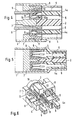
- FIG. 1 it can be seen that the invention Connector for connecting a not shown shielded cable is used from a shielded housing 1 with Separators 2 exist with the help of them within the housing 1 several separate chambers, each shielded by 360 ° 3 arise.
- the housing 1 can be made of an electrically conductive Material, for example made of a die-cast metal his. Are used in this housing, in particular can also be seen from Figures 4 to 6, insulating body 4, which hold the contacts 5 and each with protruding Pins 4a are provided, with which the contacts 5 of corresponding plugs can be contacted.
- the contacts 5 are designed as insulation displacement connections and go in their area facing away from the plug pins 4a in fork-shaped cutting terminals 6, which, like Fig. 3 shows, from the insulating bodies 4 on the connection side protrude outwards.
- These insulation displacement terminals 6 point within of the housing 1 to a made of a conductive material Contact piece 7, the one in the embodiment Cross forms on which four made of insulating material Pressure pieces 8 can be arranged, in which the shown wire ends of the shielded connection cable introduced can be. This is done, as shown in Fig.
- the pressure pieces 8 are, as can be seen in FIG. 6, on Pin 11 of the cross-shaped contact piece 7 pushed on and are kept in this position.
- the cross-shaped contact piece 7 has one in the middle Opening 12 with a thread into which a screw 13 can be inserted is through a corresponding opening 14 in the Partitions 2 of the housing 1 into the cross-shaped contact piece 7 is inserted.
- this screw 13 If this screw 13 is now tightened, then it moves cross-shaped contact piece 7 with the pressure pieces arranged thereon 8 towards the housing 1 with its partitions 2, and the insulation displacement terminals 6 of the contacts 5 enter the Openings 10 of the pressure pieces 8 and contact the wire ends 9 accordingly.
- the cable to be connected can be connected to this spike be fixed in position.
- the shielding of the cable is done with the help a squeeze ring 15 brought into contact with the contact piece 7.
- the contact piece 7 itself lies with its cross-shaped Walls on the inner wall of the housing, so that and with the help of screw 13 the shielding of the cable on the housing and, as previously described, also on the individual chambers 3 of the housing 1 is transmitted.
- the connector of the cable, as indicated in Fig. 1, from a protective cap 16 are covered over the squeeze ring 15 and can be guided over the housing 1.
- the invention therefore has a very simple structure Connector created with a sufficient Shielding can be used for analog and digital data transmission also at frequencies up to 600 MHz and allowed higher than 600 MHz. Contacting the wire ends is simply achieved. Cumbersome stripping of the cable ends and introduction into separate contact sleeves are unnecessary.
Claims (6)
- Connecteur, dans l'equel les tronçons d'extrémité des brins d'un câble à raccorder sont retenus dans des guidages de pièces de pression (8) en matériau isolant en biais à la direction d'enfichage et sont contactés par des raccords par déplacement d'isolation (5, 6) qui sont disposés dans des chambres individuelles d'un corps de support, qui est déplaçable par rapport aux pièces de pression (8) dans la direction d'enfichage, caractérisé en ce que pour le raccordement d'un câble blindé, les pièces de pression (8) sont disposées à une pièce de contact (7) constituée d'un matériau électriquement conducteur qui peut être placé dans un boítier blindé (1) servant de corps de support et vient en contact avec les parois de celui-ci, en ce que le blindage du câble peut être appliqué à la pièce de contact (7), en ce que les raccords par déplacement d'isolation (6, 5) sont disposés dans des corps isolants (4) qui sont logés dans des chambres blindées (3) du boítier (1) et en ce que le boítier (1) est relié à la pièce de contact (7) par une vis (13) s'étendant dans la direction d'enfichage.
- Connecteur selon la revendication 1, caractérisé en ce que les chambres (3) sont formées par des barrettes de séparation (2) à l'intérieur du boítier qui s'étendent en forme de croix.
- Connecteur selon la revendication 1 et 2, caractérisé en ce que la vis (13) est accessible depuis le côté de connexion ouvert du boítier et s'étend dans une ouverture (14) au milieu dans les barrettes de séparation du boítier.
- Connecteur selon les revendications 1 à 3, caractérisé en ce que la pièce de contact (7) est réalisée comme une pièce en croix avec un filetage central (12).
- Connecteur selon l'une des revendications 1 à 4, caractérisé en ce que la tresse de protection du câble est fixée avec une bague à compression (15) à la pièce de contact (7).
- Connecteur selon l'une des revendications 1 à 5, caractérisé en ce qu'un capuchon de protection (16) peut être poussé sur la bague à compression (15) et le boítier (1) .
Applications Claiming Priority (2)
| Application Number | Priority Date | Filing Date | Title |
|---|---|---|---|
| DE19811667 | 1998-03-18 | ||
| DE19811667A DE19811667C2 (de) | 1998-03-18 | 1998-03-18 | Kabelsteckverbinder |
Publications (3)
| Publication Number | Publication Date |
|---|---|
| EP0945929A2 EP0945929A2 (fr) | 1999-09-29 |
| EP0945929A3 EP0945929A3 (fr) | 2001-12-12 |
| EP0945929B1 true EP0945929B1 (fr) | 2003-05-07 |
Family
ID=7861260
Family Applications (1)
| Application Number | Title | Priority Date | Filing Date |
|---|---|---|---|
| EP99102760A Expired - Lifetime EP0945929B1 (fr) | 1998-03-18 | 1999-02-22 | Connecteur pour un câble blindé |
Country Status (3)
| Country | Link |
|---|---|
| US (1) | US6347956B2 (fr) |
| EP (1) | EP0945929B1 (fr) |
| DE (2) | DE19811667C2 (fr) |
Cited By (2)
| Publication number | Priority date | Publication date | Assignee | Title |
|---|---|---|---|---|
| DE102012111646A1 (de) | 2012-11-30 | 2014-06-05 | HARTING Electronics GmbH | Isolierkörper mit integriertem Schirmelement |
| US11557845B2 (en) | 2018-08-02 | 2023-01-17 | Harting Electric Stiftung & Co. Kg | Modular plug-in connector system |
Families Citing this family (5)
| Publication number | Priority date | Publication date | Assignee | Title |
|---|---|---|---|---|
| US6464538B2 (en) * | 2000-03-07 | 2002-10-15 | Autonetworks Technologies, Ltd. | Shield connector and terminal connecting device for shielding electric wire |
| DE202010010754U1 (de) | 2010-07-28 | 2010-10-21 | Harting Electronics Gmbh & Co. Kg | Steckverbinder mit Schneidklemmen und einem unverlierbaren Isolierkörper |
| DE102011000460A1 (de) | 2011-02-02 | 2012-08-02 | Harting Electronics Gmbh & Co. Kg | Kontaktierungsvorrichtung eines elektrischen Steckverbinders |
| USD925460S1 (en) * | 2020-12-31 | 2021-07-20 | Tower Manufacturing Corp. | LCDI connector with extension |
| USD925459S1 (en) * | 2020-12-31 | 2021-07-20 | Tower Manufacturing Corp. | LCDI connector |
Family Cites Families (11)
| Publication number | Priority date | Publication date | Assignee | Title |
|---|---|---|---|---|
| US4653825A (en) * | 1985-09-06 | 1987-03-31 | Amp Incorporated | Shielded electrical connector assembly |
| ES1004786Y (es) * | 1986-12-22 | 1989-04-01 | Amp Incorporated | Un conectador electrico. |
| US5106325A (en) * | 1990-01-19 | 1992-04-21 | Leviton Manufacturing Co. Inc. | Modular higher density communications coupling system |
| DE4203455C1 (fr) * | 1992-02-07 | 1993-06-03 | Harting Elektronik Gmbh, 4992 Espelkamp, De | |
| DE4203853C2 (de) | 1992-02-11 | 1993-11-25 | Guenter Meywald | Positioniervorrichtung für zwei zu fügende Bauteile |
| US5423694A (en) * | 1993-04-12 | 1995-06-13 | Raychem Corporation | Telecommunications terminal block |
| DE59404901D1 (de) * | 1994-09-01 | 1998-02-05 | Bks Kabel Service Ag | Stecker für ein Kabel mit mehreren Adern |
| US5571029A (en) * | 1994-11-23 | 1996-11-05 | Siecor Corporation | Insulation displacement connector |
| US5605469A (en) * | 1995-01-05 | 1997-02-25 | Thomas & Betts Corporation | Electrical connector having an improved conductor holding block and conductor shield |
| DE19650017C1 (de) * | 1996-11-22 | 1998-04-09 | Krone Ag | Klemmvorrichtung |
| US6025982A (en) * | 1998-10-01 | 2000-02-15 | Siecor Operations, Llc | Balanced wire connector |
-
1998
- 1998-03-18 DE DE19811667A patent/DE19811667C2/de not_active Expired - Fee Related
-
1999
- 1999-02-22 EP EP99102760A patent/EP0945929B1/fr not_active Expired - Lifetime
- 1999-02-22 DE DE59905397T patent/DE59905397D1/de not_active Expired - Lifetime
- 1999-03-18 US US09/271,442 patent/US6347956B2/en not_active Expired - Fee Related
Cited By (3)
| Publication number | Priority date | Publication date | Assignee | Title |
|---|---|---|---|---|
| DE102012111646A1 (de) | 2012-11-30 | 2014-06-05 | HARTING Electronics GmbH | Isolierkörper mit integriertem Schirmelement |
| WO2014082623A1 (fr) | 2012-11-30 | 2014-06-05 | HARTING Electronics GmbH | Corps isolant avec élément de blindage intégré |
| US11557845B2 (en) | 2018-08-02 | 2023-01-17 | Harting Electric Stiftung & Co. Kg | Modular plug-in connector system |
Also Published As
| Publication number | Publication date |
|---|---|
| DE19811667A1 (de) | 1999-09-30 |
| EP0945929A3 (fr) | 2001-12-12 |
| US6347956B2 (en) | 2002-02-19 |
| EP0945929A2 (fr) | 1999-09-29 |
| DE19811667C2 (de) | 2002-01-24 |
| US20010044231A1 (en) | 2001-11-22 |
| DE59905397D1 (de) | 2003-06-12 |
Similar Documents
| Publication | Publication Date | Title |
|---|---|---|
| EP2417673B1 (fr) | Connecteur électrique à fiches | |
| DE2923399C2 (de) | Verfahren zur elektrischen Verbindung eines Koaxialkabels und Anschlußarmatur für Koaxialkabel | |
| DE60126369T2 (de) | Steckverbinder mit Kontakten die in einem angepassten isolierenden Gehäuse montiert sind | |
| EP1372222B1 (fr) | Pièce de contact hermaphrodite | |
| DE69737850T2 (de) | Impedanz-angepasster Kabelzusammenbau mit Verriegelungsuntereinheit | |
| WO2015035979A1 (fr) | Connecteur enfichable | |
| EP2026417B1 (fr) | Connecteur électrique doté d'éléments de contact hermaphrodites | |
| EP2797175B1 (fr) | Fiche pour un câble de données et/ou de télécommunications multi-brins | |
| DE60105214T2 (de) | Modularer Steckverbinder und Kabelbaumsteckverbinder | |
| DE102012105257B4 (de) | Isolierkörper eines Steckverbinders | |
| EP0945929B1 (fr) | Connecteur pour un câble blindé | |
| DE102007026102B3 (de) | Steckverbinder für Leiterplatten | |
| DE4413977C2 (de) | Kabelabzweigung eines Datenbus zur Verbindung von elektronischen Steuergeräten in Personenkraftwagen und Nutzfahrzeugen | |
| EP0793299A1 (fr) | Connecteur coaxial | |
| EP2417675B1 (fr) | Boîtier de système à fiches pour câbles multiconducteurs | |
| DE3940652C2 (de) | Elektrische Steckverbindung | |
| DE102017222809B4 (de) | Elektrischer Steckverbinder und Steckverbindung | |
| DE3427361C1 (de) | Verbindung zwischen einem koaxialen Steckverbinder und einem Koaxialkabel | |
| AT399427B (de) | Audio-buchsen-stecker | |
| EP1020954A2 (fr) | Borne de connexion électrique | |
| DE19921132C1 (de) | Kabelstecker für elektrische Verbindungen | |
| EP0952626B1 (fr) | Connecteur | |
| DE19518828C2 (de) | Flachsteckhülse | |
| DE60112139T2 (de) | Aufbau eines abgeschirmten Hochfrequenzkabels | |
| EP0852080B1 (fr) | Procede de mise en contact d'un connecteur multipolaire a ressort |
Legal Events
| Date | Code | Title | Description |
|---|---|---|---|
| PUAI | Public reference made under article 153(3) epc to a published international application that has entered the european phase |
Free format text: ORIGINAL CODE: 0009012 |
|
| AK | Designated contracting states |
Kind code of ref document: A2 Designated state(s): AT BE CH CY DE DK ES FI FR GB GR IE IT LI LU MC NL PT SE Kind code of ref document: A2 Designated state(s): CH DE FR GB IT LI |
|
| AX | Request for extension of the european patent |
Free format text: AL;LT;LV;MK;RO;SI |
|
| PUAL | Search report despatched |
Free format text: ORIGINAL CODE: 0009013 |
|
| AK | Designated contracting states |
Kind code of ref document: A3 Designated state(s): AT BE CH CY DE DK ES FI FR GB GR IE IT LI LU MC NL PT SE |
|
| AX | Request for extension of the european patent |
Free format text: AL;LT;LV;MK;RO;SI |
|
| 17P | Request for examination filed |
Effective date: 20020531 |
|
| GRAH | Despatch of communication of intention to grant a patent |
Free format text: ORIGINAL CODE: EPIDOS IGRA |
|
| AKX | Designation fees paid |
Free format text: CH DE FR GB IT LI |
|
| GRAH | Despatch of communication of intention to grant a patent |
Free format text: ORIGINAL CODE: EPIDOS IGRA |
|
| GRAA | (expected) grant |
Free format text: ORIGINAL CODE: 0009210 |
|
| AK | Designated contracting states |
Designated state(s): CH DE FR GB IT LI |
|
| REG | Reference to a national code |
Ref country code: GB Ref legal event code: FG4D Free format text: NOT ENGLISH |
|
| REG | Reference to a national code |
Ref country code: CH Ref legal event code: EP |
|
| REG | Reference to a national code |
Ref country code: IE Ref legal event code: FG4D Free format text: GERMAN |
|
| REF | Corresponds to: |
Ref document number: 59905397 Country of ref document: DE Date of ref document: 20030612 Kind code of ref document: P |
|
| REG | Reference to a national code |
Ref country code: CH Ref legal event code: NV Representative=s name: ZIMMERLI, WAGNER & PARTNER AG |
|
| GBT | Gb: translation of ep patent filed (gb section 77(6)(a)/1977) | ||
| RAP2 | Party data changed (patent owner data changed or rights of a patent transferred) |
Owner name: HARTING ELECTRIC GMBH & CO. KG Owner name: ALBERT ACKERMANN GMBH & CO. KG |
|
| REG | Reference to a national code |
Ref country code: IE Ref legal event code: FD4D Ref document number: 0945929E Country of ref document: IE |
|
| PLBE | No opposition filed within time limit |
Free format text: ORIGINAL CODE: 0009261 |
|
| STAA | Information on the status of an ep patent application or granted ep patent |
Free format text: STATUS: NO OPPOSITION FILED WITHIN TIME LIMIT |
|
| ET | Fr: translation filed | ||
| 26N | No opposition filed |
Effective date: 20040210 |
|
| REG | Reference to a national code |
Ref country code: GB Ref legal event code: 732E |
|
| REG | Reference to a national code |
Ref country code: CH Ref legal event code: PUE Owner name: HARTING ELECTRIC GMBH & CO. KG Free format text: ALBERT ACKERMANN GMBH & CO. KG#ALBERTSTRASSE 4-8#51643 GUMMERSBACH (DE) $ HARTING KGAA#MARIENWERDERSTRASSE 3#32339 ESPELKAMP (DE) -TRANSFER TO- HARTING ELECTRIC GMBH & CO. KG#WILHELM-HARTING-STRASSE 1#32339 ESPELKAMP (DE) $ NOVAR GMBH#JOHANNES-MAUTHE-STRASSE 14#72458 ALBSTADT-EBINGEN (DE) |
|
| REG | Reference to a national code |
Ref country code: GB Ref legal event code: 732E |
|
| REG | Reference to a national code |
Ref country code: FR Ref legal event code: TQ |
|
| REG | Reference to a national code |
Ref country code: HK Ref legal event code: WD Ref document number: 1022995 Country of ref document: HK |
|
| REG | Reference to a national code |
Ref country code: CH Ref legal event code: PFA Owner name: HARTING ELECTRIC GMBH & CO. KG Free format text: HARTING ELECTRIC GMBH & CO. KG#WILHELM-HARTING-STRASSE 1#32339 ESPELKAMP (DE) $ NOVAR GMBH#JOHANNES-MAUTHE-STRASSE 14#72458 ALBSTADT-EBINGEN (DE) -TRANSFER TO- HARTING ELECTRIC GMBH & CO. KG#WILHELM-HARTING-STRASSE 1#32339 ESPELKAMP (DE) $ NOVAR GMBH#JOHANNES-MAUTHE-STRASSE 14#72458 ALBSTADT-EBINGEN (DE) |
|
| PGFP | Annual fee paid to national office [announced via postgrant information from national office to epo] |
Ref country code: IT Payment date: 20120224 Year of fee payment: 14 |
|
| PGFP | Annual fee paid to national office [announced via postgrant information from national office to epo] |
Ref country code: GB Payment date: 20130219 Year of fee payment: 15 Ref country code: CH Payment date: 20130220 Year of fee payment: 15 Ref country code: FR Payment date: 20130315 Year of fee payment: 15 Ref country code: DE Payment date: 20130307 Year of fee payment: 15 |
|
| REG | Reference to a national code |
Ref country code: CH Ref legal event code: NV Representative=s name: WAGNER PATENT AG, CH |
|
| REG | Reference to a national code |
Ref country code: DE Ref legal event code: R119 Ref document number: 59905397 Country of ref document: DE |
|
| REG | Reference to a national code |
Ref country code: CH Ref legal event code: PL |
|
| GBPC | Gb: european patent ceased through non-payment of renewal fee |
Effective date: 20140222 |
|
| PG25 | Lapsed in a contracting state [announced via postgrant information from national office to epo] |
Ref country code: CH Free format text: LAPSE BECAUSE OF NON-PAYMENT OF DUE FEES Effective date: 20140228 Ref country code: LI Free format text: LAPSE BECAUSE OF NON-PAYMENT OF DUE FEES Effective date: 20140228 |
|
| REG | Reference to a national code |
Ref country code: FR Ref legal event code: ST Effective date: 20141031 |
|
| REG | Reference to a national code |
Ref country code: DE Ref legal event code: R119 Ref document number: 59905397 Country of ref document: DE Effective date: 20140902 |
|
| PG25 | Lapsed in a contracting state [announced via postgrant information from national office to epo] |
Ref country code: GB Free format text: LAPSE BECAUSE OF NON-PAYMENT OF DUE FEES Effective date: 20140222 Ref country code: FR Free format text: LAPSE BECAUSE OF NON-PAYMENT OF DUE FEES Effective date: 20140228 Ref country code: DE Free format text: LAPSE BECAUSE OF NON-PAYMENT OF DUE FEES Effective date: 20140902 |
|
| PG25 | Lapsed in a contracting state [announced via postgrant information from national office to epo] |
Ref country code: IT Free format text: LAPSE BECAUSE OF NON-PAYMENT OF DUE FEES Effective date: 20140222 |