EP0945929B1 - Connector for shielded cable - Google Patents
Connector for shielded cable Download PDFInfo
- Publication number
- EP0945929B1 EP0945929B1 EP99102760A EP99102760A EP0945929B1 EP 0945929 B1 EP0945929 B1 EP 0945929B1 EP 99102760 A EP99102760 A EP 99102760A EP 99102760 A EP99102760 A EP 99102760A EP 0945929 B1 EP0945929 B1 EP 0945929B1
- Authority
- EP
- European Patent Office
- Prior art keywords
- housing
- cable
- contact element
- connector
- shielded
- Prior art date
- Legal status (The legal status is an assumption and is not a legal conclusion. Google has not performed a legal analysis and makes no representation as to the accuracy of the status listed.)
- Expired - Lifetime
Links
Images

Classifications
-
- H—ELECTRICITY
- H01—ELECTRIC ELEMENTS
- H01R—ELECTRICALLY-CONDUCTIVE CONNECTIONS; STRUCTURAL ASSOCIATIONS OF A PLURALITY OF MUTUALLY-INSULATED ELECTRICAL CONNECTING ELEMENTS; COUPLING DEVICES; CURRENT COLLECTORS
- H01R13/00—Details of coupling devices of the kinds covered by groups H01R12/70 or H01R24/00 - H01R33/00
- H01R13/648—Protective earth or shield arrangements on coupling devices, e.g. anti-static shielding
- H01R13/658—High frequency shielding arrangements, e.g. against EMI [Electro-Magnetic Interference] or EMP [Electro-Magnetic Pulse]
- H01R13/6591—Specific features or arrangements of connection of shield to conductive members
- H01R13/6592—Specific features or arrangements of connection of shield to conductive members the conductive member being a shielded cable
- H01R13/6593—Specific features or arrangements of connection of shield to conductive members the conductive member being a shielded cable the shield being composed of different pieces
-
- H—ELECTRICITY
- H01—ELECTRIC ELEMENTS
- H01R—ELECTRICALLY-CONDUCTIVE CONNECTIONS; STRUCTURAL ASSOCIATIONS OF A PLURALITY OF MUTUALLY-INSULATED ELECTRICAL CONNECTING ELEMENTS; COUPLING DEVICES; CURRENT COLLECTORS
- H01R13/00—Details of coupling devices of the kinds covered by groups H01R12/70 or H01R24/00 - H01R33/00
- H01R13/46—Bases; Cases
- H01R13/502—Bases; Cases composed of different pieces
- H01R13/512—Bases; Cases composed of different pieces assembled by screw or screws
-
- H—ELECTRICITY
- H01—ELECTRIC ELEMENTS
- H01R—ELECTRICALLY-CONDUCTIVE CONNECTIONS; STRUCTURAL ASSOCIATIONS OF A PLURALITY OF MUTUALLY-INSULATED ELECTRICAL CONNECTING ELEMENTS; COUPLING DEVICES; CURRENT COLLECTORS
- H01R4/00—Electrically-conductive connections between two or more conductive members in direct contact, i.e. touching one another; Means for effecting or maintaining such contact; Electrically-conductive connections having two or more spaced connecting locations for conductors and using contact members penetrating insulation
- H01R4/24—Connections using contact members penetrating or cutting insulation or cable strands
- H01R4/2416—Connections using contact members penetrating or cutting insulation or cable strands the contact members having insulation-cutting edges, e.g. of tuning fork type
- H01R4/242—Connections using contact members penetrating or cutting insulation or cable strands the contact members having insulation-cutting edges, e.g. of tuning fork type the contact members being plates having a single slot
Definitions
- the invention relates to a connector in which the end sections the wires of a cable to be connected in guides of pressure pieces made of insulating material at an angle to the direction of insertion held and contacted by insulation displacement connections are arranged in individual chambers of a carrier body are the opposite of the pressure pieces in the direction of insertion is movable.
- a connector of this type is known from EP 0 554 810 A2.
- Such connectors have the advantage that Insulation displacement connection of the contact elements is extremely simple is and a contact by pressing is achieved by two parts of an insulating body.
- Connectors this known type is not readily suitable two-, four- or eight-pin connectors for analog and to create digital data transmission that is in shielded Execution also at frequencies up to 600 MHz and higher 600 MHz can be used.
- the type mentioned above for connecting a shielded cable provided that the pressure pieces on an electrically conductive Material existing contact piece are arranged, the can be used in a shielded housing serving as a carrier body is and its walls contacted that the shield of the cable can be attached to the contact piece that the Insulation displacement connections are arranged in insulating bodies that are housed in shielded chambers of the housing, which are formed by separators within the housing, and that the housing with the contact piece by a in the direction of insertion extending screw is connected in contact.
- This configuration makes it relatively simple possible after loosening the braid of the one to be connected Cable the free wire ends into their assigned pressure pieces introduce where they are held at an angle to the direction of insertion, then assign these pressure pieces to the conductive contact piece and the latter after being connected to the cable shield is to pull through the screw into the socket housing, then on the one hand the contact to the shielded housing the contact piece and the screw and on the other hand the contacting the wires are made by the screwing process.
- the screw can in a development of the invention be accessible from the open connection side of the housing, so that there are no assembly difficulties.
- the contact piece as a Cross piece to be formed with a central thread with the shielding of the cable in a manner known per se a crimp ring is attached.
- the connector housing can also one Protective cap can be pushed over.
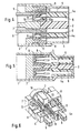
- FIG. 1 it can be seen that the invention Connector for connecting a not shown shielded cable is used from a shielded housing 1 with Separators 2 exist with the help of them within the housing 1 several separate chambers, each shielded by 360 ° 3 arise.
- the housing 1 can be made of an electrically conductive Material, for example made of a die-cast metal his. Are used in this housing, in particular can also be seen from Figures 4 to 6, insulating body 4, which hold the contacts 5 and each with protruding Pins 4a are provided, with which the contacts 5 of corresponding plugs can be contacted.
- the contacts 5 are designed as insulation displacement connections and go in their area facing away from the plug pins 4a in fork-shaped cutting terminals 6, which, like Fig. 3 shows, from the insulating bodies 4 on the connection side protrude outwards.
- These insulation displacement terminals 6 point within of the housing 1 to a made of a conductive material Contact piece 7, the one in the embodiment Cross forms on which four made of insulating material Pressure pieces 8 can be arranged, in which the shown wire ends of the shielded connection cable introduced can be. This is done, as shown in Fig.
- the pressure pieces 8 are, as can be seen in FIG. 6, on Pin 11 of the cross-shaped contact piece 7 pushed on and are kept in this position.
- the cross-shaped contact piece 7 has one in the middle Opening 12 with a thread into which a screw 13 can be inserted is through a corresponding opening 14 in the Partitions 2 of the housing 1 into the cross-shaped contact piece 7 is inserted.
- this screw 13 If this screw 13 is now tightened, then it moves cross-shaped contact piece 7 with the pressure pieces arranged thereon 8 towards the housing 1 with its partitions 2, and the insulation displacement terminals 6 of the contacts 5 enter the Openings 10 of the pressure pieces 8 and contact the wire ends 9 accordingly.
- the cable to be connected can be connected to this spike be fixed in position.
- the shielding of the cable is done with the help a squeeze ring 15 brought into contact with the contact piece 7.
- the contact piece 7 itself lies with its cross-shaped Walls on the inner wall of the housing, so that and with the help of screw 13 the shielding of the cable on the housing and, as previously described, also on the individual chambers 3 of the housing 1 is transmitted.
- the connector of the cable, as indicated in Fig. 1, from a protective cap 16 are covered over the squeeze ring 15 and can be guided over the housing 1.
- the invention therefore has a very simple structure Connector created with a sufficient Shielding can be used for analog and digital data transmission also at frequencies up to 600 MHz and allowed higher than 600 MHz. Contacting the wire ends is simply achieved. Cumbersome stripping of the cable ends and introduction into separate contact sleeves are unnecessary.
Description
Die Erfindung betrifft einen Steckverbinder, bei dem die Endabschnitte der Adern eines anzuschließenden Kabels in Führungen von Druckstücken aus Isoliermaterial schräg zur Steckrichtung gehalten und von Schneidklemmanschlüssen kontaktiert werden, die in einzelnen Kammern eines Trägerkörpers angeordnet sind, der gegenüber den Druckstücken in der Steckrichtung verschiebbar ist.The invention relates to a connector in which the end sections the wires of a cable to be connected in guides of pressure pieces made of insulating material at an angle to the direction of insertion held and contacted by insulation displacement connections are arranged in individual chambers of a carrier body are the opposite of the pressure pieces in the direction of insertion is movable.
Ein Steckverbinder dieser Art ist aus der EP 0 554 810 A2 bekannt. Solche Steckverbinder weisen den Vorteil auf, daß der Schneidklemmanschluß der Kontaktelemente äußerst einfach ausgebildet ist und eine Kontaktierung durch das Zusammendrücken von zwei Teilen eines Isolierkörpers erreicht wird. Steckverbinder dieser bekannten Art sind aber nicht ohne weiteres geeignet zwei-, vier- oder acht-polige Steckverbinder für analoge und digitale Datenübertragung zu schaffen, die in geschirmter Ausführung auch bei Frequenzen bis 600 MHz und größer 600 MHz einsetzbar sind.A connector of this type is known from EP 0 554 810 A2. Such connectors have the advantage that Insulation displacement connection of the contact elements is extremely simple is and a contact by pressing is achieved by two parts of an insulating body. Connectors However, this known type is not readily suitable two-, four- or eight-pin connectors for analog and to create digital data transmission that is in shielded Execution also at frequencies up to 600 MHz and higher 600 MHz can be used.
Bekannt ist es auch, geschirmte Steckverbinder nach der IEC-Bauart Spezifikation 603-7 vorzusehen. Es hat sich jedoch gezeigt, daß diese Steckverbinder für Frequenzen oberhalb 200 MHz nicht ausreichend sind, da die Einfügedämpfung, die Reflexionsdämpfung und die Nah-Nebensprechdämpfung die geforderten Werte nicht einhalten.It is also known to use shielded connectors according to the IEC design To provide specification 603-7. However, it has been shown that these connectors for frequencies above 200 MHz are not sufficient because the insertion loss, the reflection loss and the near-crosstalk attenuation the required Do not adhere to values.
Es ist daher die Aufgabe der vorliegenden Erfindung, einen Steckverbinder der eingangs genannten Art, bei dem die Kontaktierung in sehr einfacher Weise vorgenommen werden kann, ohne daß die Kabelenden abisoliert zu werden brauchen, nun auch als geschirmte Steckverbindung auszubilden.It is therefore the object of the present invention, one Connector of the type mentioned, in which the contacting can be done in a very simple way without the cable ends needing to be stripped, well also be designed as a shielded connector.
Zur Lösung dieser Aufgabe wird bei einem Steckverbinder der eingangs genannten Art zum Anschluß eines geschirmten Kabels vorgesehen, daß die Druckstücke an einem aus elektrisch leitendem Material bestehenden Kontaktstück angeordnet sind, das in ein als Trägerkörper dienendes geschirmtes Gehäuse einsetzbar ist und dessen Wandungen kontaktiert, daß die Schirmung des Kabels an dem Kontaktstück anbringbar ist, daß die Schneidklemmanschlüsse in Isolierkörpern angeordnet sind, die in geschirmten Kammern des Gehäuses untergebracht sind, die durch Trennstege innerhalb des Gehäuses gebildet werden, und daß das Gehäuse mit dem Kontaktstück durch eine in Steckrichtung verlaufende Schraube kontaktierend verbunden ist.To solve this problem, the type mentioned above for connecting a shielded cable provided that the pressure pieces on an electrically conductive Material existing contact piece are arranged, the can be used in a shielded housing serving as a carrier body is and its walls contacted that the shield of the cable can be attached to the contact piece that the Insulation displacement connections are arranged in insulating bodies that are housed in shielded chambers of the housing, which are formed by separators within the housing, and that the housing with the contact piece by a in the direction of insertion extending screw is connected in contact.
Durch diese Ausgestaltung wird es in relativ einfacher Weise möglich, nach Lösen des Schirmgeflechts des anzuschließenden Kabels die freien Aderenden in ihre zugeordneten Druckstücke einzuführen, wo sie schräg zur Steckrichtung gehalten werden, dann diese Druckstücke dem leitenden Kontaktstück zuzuordnen und letzteres nachdem es mit der Kabelschirmung verbunden ist, durch die Schraube in das Buchsengehäuse hineinzuziehen, wobei dann zum einen der Kontakt zum geschirmten Gehäuse über das Kontaktstück und die Schraube und zum anderen die Kontaktierung der Adern durch den Schraubvorgang erfolgt.This configuration makes it relatively simple possible after loosening the braid of the one to be connected Cable the free wire ends into their assigned pressure pieces introduce where they are held at an angle to the direction of insertion, then assign these pressure pieces to the conductive contact piece and the latter after being connected to the cable shield is to pull through the screw into the socket housing, then on the one hand the contact to the shielded housing the contact piece and the screw and on the other hand the contacting the wires are made by the screwing process.
Die Schraube kann dabei in Weiterbildung der Erfindung von der offenen Anschlußseite des Gehäuses her zugänglich sein, so daß keine Montageschwierigkeit auftreten. The screw can in a development of the invention be accessible from the open connection side of the housing, so that there are no assembly difficulties.
In Weiterbildung der Erfindung kann das Kontaktstück als ein Kreuzstück mit einem mittigen Gewinde ausgebildet sein, an dem die Schirmung des Kabels in an sich bekannter Weise mit einem Quetschring angebracht wird. Über diesen Quetschring und das Steckergehäuse kann schließlich auch noch eine Schutzkappe überschiebbar sein.In a further development of the invention, the contact piece as a Cross piece to be formed with a central thread with the shielding of the cable in a manner known per se a crimp ring is attached. About this squeeze ring and finally the connector housing can also one Protective cap can be pushed over.
Die Erfindung ist anhand eines Ausführungsbeispieles in der Zeichnung dargestellt und wird im folgenden erläutert. Es zeigen:
- Fig. 1
- eine perspektivische Explosionszeichnung eines Steck- verbinders nach der Erfindung,
- Fig. 2
- die vergrößerte Darstellung des Steckverbinders von der Steckseite her,
- Fig. 3
- die Darstellung des Steckverbindergehäuses nach Fig. 2 von der Anschlußseite her,
- Fig. 4
- die schematische Darstellung des Längsschnittes durch das Steckverbindergehäuse der Fig. 2 in Richtung der Linie IV,
- Fig. 5
- den Längsschnitt durch das Steckverbindergehäuse der Fig. 2 in Richtung der Schnittlinie V, und
- Fig. 6
- eine schematische perspektivische Darstellung der in- neren Teile des Steckverbindergehäuses der Fig. 2
- Fig. 1
- 2 shows an exploded perspective view of a connector according to the invention,
- Fig. 2
- the enlarged view of the connector from the plug side,
- Fig. 3
- the representation of the connector housing of FIG. 2 from the connection side,
- Fig. 4
- the schematic representation of the longitudinal section through the connector housing of FIG. 2 in the direction of line IV,
- Fig. 5
- the longitudinal section through the connector housing of FIG. 2 in the direction of section line V, and
- Fig. 6
- 2 shows a schematic perspective illustration of the inner parts of the connector housing of FIG. 2
Aus der Fig. 1 ist zu erkennen, daß der erfindungsgemäße
Steckverbinder, der zum Anschluß eines nicht näher gezeigten
geschirmten Kabels dient, aus einem geschirmten Gehäuse 1 mit
Trennstegen 2 besteht, mit deren Hilfe innerhalb des Gehäuses
1 mehrere getrennte, jeweils um 360° geschirmte Kammern 3
entstehen. Das Gehäuse 1 kann aus einem elektrisch leitenden
Material, beispielsweise aus einem Metalldruckguß, hergestellt
sein. In dieses Gehäuse eingesetzt sind, wie insbesondere
auch aus den Figuren 4 bis 6 erkennbar ist, Isolierkörper
4, welche die Kontakte 5 halten und jeweils mit abstehenden
Zapfen 4a versehen sind, mit denen die Kontakte 5 von
entsprechenden Steckern kontaktiert werden können.From Fig. 1 it can be seen that the invention
Connector for connecting a not shown
shielded cable is used from a shielded
Die Kontakte 5 sind als Schneidklemmanschlüsse ausgebildet
und gehen in ihrem von den Steckzapfen 4a abgewandten Bereich
in gabelartig ausgebildete Schneidklemmen 6 über, die, wie
Fig. 3 zeigt, aus den Isolierkörpern 4 auf der Anschlußseite
nach außen vorstehen. Diese Schneidklemmen 6 weisen innerhalb
des Gehäuses 1 zu einem aus einem leitenden Material hergestellten
Kontaktstück 7, das beim Ausführungsbeispiel ein
Kreuz bildet, an dem vier aus Isoliermaterial bestehende
Druckstücke 8 angeordnet werden können, in welche die nicht
gezeigten Aderenden des geschirmten Anschlußkabels eingeführt
werden können. Dies geschieht, wie Fig. 4 zeigt, dadurch, daß
die nicht abisolierten Adernenden 9 in Führungen 10 innerhalb
der Druckstücke 4 in der späteren Steckrichtung eingeführt
wird und dort, weil die Führungen einen schräg zur Steckrichtung
verlaufenden Abschnitt 10a aufweisen, auf einem Teil ihrer
Länge schräg zur späteren Steck- und Montagerichtung verlaufen.The
Die Druckstücke 8 sind, wie Fig. 6 erkennen läßt, dabei auf
Zapfen 11 des kreuzförmigen Kontaktstückes 7 aufgeschoben und
werden so in ihrer Lage gehalten.The
Das kreuzförmige Kontaktstück 7 besitzt in seiner Mitte eine
Öffnung 12 mit einem Gewinde, in das eine Schraube 13 einführbar
ist, die durch eine entsprechende Öffnung 14 in den
Trennwänden 2 des Gehäuses 1 bis in das kreuzförmige Kontaktstück
7 hindurchgesteckt ist.The
Wird nun diese Schraube 13 angezogen, dann bewegt sich das
kreuzförmige Kontaktstück 7 mit den daran angeordneten Druckstücken
8 in Richtung auf das Gehäuse 1 mit seinen Trennwänden
2, und die Schneidklemmen 6 der Kontakte 5 treten in die
Öffnungen 10 der Druckstücke 8 ein und kontaktieren die Aderenden
9 entsprechend.If this
An dem Kontaktstück 7 ist auf der von der Schraube 13 abgewandten
Seite mittig ein kleiner Dorn angeordnet, der nicht
gezeigt ist. An diesem Dorn kann das anzuschließende Kabel
lagefixiert werden. Die Schirmung des Kabels wird mit Hilfe
eines Quetschringes 15 in Kontakt mit dem Kontaktstück 7 gebracht.
Das Kontaktstück 7 selbst liegt mit seinen kreuzförmigen
Wänden an der Innenwandung des Gehäuses an, so daß dadurch
und mit Hilfe der Schraube 13 die Schirmung des Kabels
auf das Gehäuse und, wie vorher geschildert, auch auf die
einzelnen Kammern 3 des Gehäuses 1 übertragen wird. Der Anschlußteil
des Kabels kann, wie in Fig. 1 angedeutet ist, von
einer Schutzkappe 16 überdeckt werden, die über den Quetschring
15 und über das Gehäuse 1 geführt werden kann.On the
Durch die Erfindung ist daher ein sehr einfach aufgebauter Steckverbinder geschaffen, der sich mit einer ausreichenden Schirmung versehen läßt, die den Einsatz für die analoge und digitale Datenübertragung auch bei Frequenzen bis 600 MHz und höher als 600 MHz erlaubt. Die Kontaktierung der Aderenden wird einfach erreicht. Umständliche Abisolierung der Kabelenden und Einführung in gesonderte Kontakthülsen werden überflüssig.The invention therefore has a very simple structure Connector created with a sufficient Shielding can be used for analog and digital data transmission also at frequencies up to 600 MHz and allowed higher than 600 MHz. Contacting the wire ends is simply achieved. Cumbersome stripping of the cable ends and introduction into separate contact sleeves are unnecessary.
Claims (6)
- Connector, in which the end portions of wires of a cable to be connected are held in guides of compressive elements (8) made of insulating material at an angle relative to the direction of insertion and are in contact with insulation displacement connectors (6, 5) which are arranged in individual chambers of a support body which is displaceable relative to the compressive elements (8) in the direction of insertion,
characterised in that
for the connection of a shielded cable, the compressive elements (8) are arranged on a contact element (7) consisting of electrically conductive material, which contact element (7) can be inserted into a shielded housing (1) serving as the support body and comes into contact with the walls thereof, in that shielding of the cable can be attached to the contact element (7), in that the insulation displacement connectors (6, 5) are arranged in insulating bodies (4) which are accommodated in shielded chambers (3) of the housing (1), and in that the housing (1) is joined to the contact element (7) by a screw (13) extending in the direction of insertion. - Connector according to claim 1, characterised in that the chambers (3) are formed by separating webs (2) inside the housing which extend in the form of a cross.
- Connector according to claim 1 and 2, characterised in that the screw (13) is accessible from the open connecting side of the housing and extends in an opening (14) in the middle of the separating webs of the housing.
- Connector according to claims 1 to 3, characterised in that the contact element (7) is in the form of a cross-shaped element having a central thread (12).
- Connector according to any one of claims 1 to 4, characterised in that the shielding mesh of the cable is attached to the contact element (7) by means of a squeezing ring (15).
- Connector according to any one of claims 1 to 5, characterised in that a protective cap (6) can be slid over the squeezing ring (15) and the housing (1).
Applications Claiming Priority (2)
| Application Number | Priority Date | Filing Date | Title |
|---|---|---|---|
| DE19811667A DE19811667C2 (en) | 1998-03-18 | 1998-03-18 | cable connector |
| DE19811667 | 1998-03-18 |
Publications (3)
| Publication Number | Publication Date |
|---|---|
| EP0945929A2 EP0945929A2 (en) | 1999-09-29 |
| EP0945929A3 EP0945929A3 (en) | 2001-12-12 |
| EP0945929B1 true EP0945929B1 (en) | 2003-05-07 |
Family
ID=7861260
Family Applications (1)
| Application Number | Title | Priority Date | Filing Date |
|---|---|---|---|
| EP99102760A Expired - Lifetime EP0945929B1 (en) | 1998-03-18 | 1999-02-22 | Connector for shielded cable |
Country Status (3)
| Country | Link |
|---|---|
| US (1) | US6347956B2 (en) |
| EP (1) | EP0945929B1 (en) |
| DE (2) | DE19811667C2 (en) |
Cited By (2)
| Publication number | Priority date | Publication date | Assignee | Title |
|---|---|---|---|---|
| DE102012111646A1 (en) | 2012-11-30 | 2014-06-05 | HARTING Electronics GmbH | Insulating body with integrated screen element |
| US11557845B2 (en) | 2018-08-02 | 2023-01-17 | Harting Electric Stiftung & Co. Kg | Modular plug-in connector system |
Families Citing this family (5)
| Publication number | Priority date | Publication date | Assignee | Title |
|---|---|---|---|---|
| EP1133022B1 (en) * | 2000-03-07 | 2008-04-30 | Autonetworks Technologies, Ltd. | Shield connector and terminal connecting device for shielding electric wire |
| DE202010010754U1 (en) | 2010-07-28 | 2010-10-21 | Harting Electronics Gmbh & Co. Kg | Connector with insulation displacement terminals and a captive insulating body |
| DE102011000460A1 (en) | 2011-02-02 | 2012-08-02 | Harting Electronics Gmbh & Co. Kg | Contacting device of an electrical connector |
| USD925459S1 (en) * | 2020-12-31 | 2021-07-20 | Tower Manufacturing Corp. | LCDI connector |
| USD925460S1 (en) * | 2020-12-31 | 2021-07-20 | Tower Manufacturing Corp. | LCDI connector with extension |
Family Cites Families (11)
| Publication number | Priority date | Publication date | Assignee | Title |
|---|---|---|---|---|
| US4653825A (en) * | 1985-09-06 | 1987-03-31 | Amp Incorporated | Shielded electrical connector assembly |
| ES1004786Y (en) * | 1986-12-22 | 1989-04-01 | Amp Incorporated | AN ELECTRICAL CONNECTOR. |
| US5106325A (en) * | 1990-01-19 | 1992-04-21 | Leviton Manufacturing Co. Inc. | Modular higher density communications coupling system |
| DE4203455C1 (en) * | 1992-02-07 | 1993-06-03 | Harting Elektronik Gmbh, 4992 Espelkamp, De | |
| DE4203853C2 (en) | 1992-02-11 | 1993-11-25 | Guenter Meywald | Positioning device for two components to be joined |
| US5423694A (en) * | 1993-04-12 | 1995-06-13 | Raychem Corporation | Telecommunications terminal block |
| ATE161663T1 (en) * | 1994-09-01 | 1998-01-15 | Bks Kabel Service Ag | CONNECTOR FOR A CABLE WITH MULTIPLE WIRE |
| US5571029A (en) * | 1994-11-23 | 1996-11-05 | Siecor Corporation | Insulation displacement connector |
| US5605469A (en) * | 1995-01-05 | 1997-02-25 | Thomas & Betts Corporation | Electrical connector having an improved conductor holding block and conductor shield |
| DE19650017C1 (en) * | 1996-11-22 | 1998-04-09 | Krone Ag | Clamping device |
| US6025982A (en) * | 1998-10-01 | 2000-02-15 | Siecor Operations, Llc | Balanced wire connector |
-
1998
- 1998-03-18 DE DE19811667A patent/DE19811667C2/en not_active Expired - Fee Related
-
1999
- 1999-02-22 EP EP99102760A patent/EP0945929B1/en not_active Expired - Lifetime
- 1999-02-22 DE DE59905397T patent/DE59905397D1/en not_active Expired - Lifetime
- 1999-03-18 US US09/271,442 patent/US6347956B2/en not_active Expired - Fee Related
Cited By (3)
| Publication number | Priority date | Publication date | Assignee | Title |
|---|---|---|---|---|
| DE102012111646A1 (en) | 2012-11-30 | 2014-06-05 | HARTING Electronics GmbH | Insulating body with integrated screen element |
| WO2014082623A1 (en) | 2012-11-30 | 2014-06-05 | HARTING Electronics GmbH | Insulating body having an integrated shield element |
| US11557845B2 (en) | 2018-08-02 | 2023-01-17 | Harting Electric Stiftung & Co. Kg | Modular plug-in connector system |
Also Published As
| Publication number | Publication date |
|---|---|
| EP0945929A2 (en) | 1999-09-29 |
| DE19811667A1 (en) | 1999-09-30 |
| US6347956B2 (en) | 2002-02-19 |
| US20010044231A1 (en) | 2001-11-22 |
| EP0945929A3 (en) | 2001-12-12 |
| DE19811667C2 (en) | 2002-01-24 |
| DE59905397D1 (en) | 2003-06-12 |
Similar Documents
| Publication | Publication Date | Title |
|---|---|---|
| EP2417673B1 (en) | Electrical plug-in connector | |
| DE2923399C2 (en) | Method for the electrical connection of a coaxial cable and connection fitting for coaxial cables | |
| DE60126369T2 (en) | Connectors with contacts mounted in a customized insulating housing | |
| EP1372222B1 (en) | Hermaphroditic contact piece | |
| DE69737850T2 (en) | Impedance-matched cable assembly with locking subunit | |
| WO2015035979A1 (en) | Connector | |
| EP2026417B1 (en) | Electrical connector with hermaphroditic contact elements | |
| EP2797175B1 (en) | Connector for a data and/or telecommunication cable comprising several wires | |
| DE60105214T2 (en) | Modular connector and harness connector | |
| DE102012105257B4 (en) | Insulator of a connector | |
| EP0945929B1 (en) | Connector for shielded cable | |
| DE102007026102B3 (en) | Connectors for printed circuit boards | |
| DE4413977C2 (en) | Cable junction of a data bus for connecting electronic control units in passenger cars and commercial vehicles | |
| EP0793299A1 (en) | Coaxial connector | |
| EP2417675B1 (en) | Plug system housing for multi-core cables | |
| DE3940652C2 (en) | Electrical connector | |
| DE102017222809B4 (en) | Electrical connector and connector | |
| DE3427361C1 (en) | Connection between a coaxial plug connector and a coaxial cable | |
| AT399427B (en) | Audio female connector | |
| EP1020954A2 (en) | Electric connecting terminal | |
| DE19921132C1 (en) | Cable connector for electrical connections | |
| EP0952626B1 (en) | Connector | |
| DE19518828C2 (en) | Blade receptacle | |
| DE60112139T2 (en) | Construction of a shielded high-frequency cable | |
| EP0852080B1 (en) | Method for contacting a multiway socket connector |
Legal Events
| Date | Code | Title | Description |
|---|---|---|---|
| PUAI | Public reference made under article 153(3) epc to a published international application that has entered the european phase |
Free format text: ORIGINAL CODE: 0009012 |
|
| AK | Designated contracting states |
Kind code of ref document: A2 Designated state(s): AT BE CH CY DE DK ES FI FR GB GR IE IT LI LU MC NL PT SE Kind code of ref document: A2 Designated state(s): CH DE FR GB IT LI |
|
| AX | Request for extension of the european patent |
Free format text: AL;LT;LV;MK;RO;SI |
|
| PUAL | Search report despatched |
Free format text: ORIGINAL CODE: 0009013 |
|
| AK | Designated contracting states |
Kind code of ref document: A3 Designated state(s): AT BE CH CY DE DK ES FI FR GB GR IE IT LI LU MC NL PT SE |
|
| AX | Request for extension of the european patent |
Free format text: AL;LT;LV;MK;RO;SI |
|
| 17P | Request for examination filed |
Effective date: 20020531 |
|
| GRAH | Despatch of communication of intention to grant a patent |
Free format text: ORIGINAL CODE: EPIDOS IGRA |
|
| AKX | Designation fees paid |
Free format text: CH DE FR GB IT LI |
|
| GRAH | Despatch of communication of intention to grant a patent |
Free format text: ORIGINAL CODE: EPIDOS IGRA |
|
| GRAA | (expected) grant |
Free format text: ORIGINAL CODE: 0009210 |
|
| AK | Designated contracting states |
Designated state(s): CH DE FR GB IT LI |
|
| REG | Reference to a national code |
Ref country code: GB Ref legal event code: FG4D Free format text: NOT ENGLISH |
|
| REG | Reference to a national code |
Ref country code: CH Ref legal event code: EP |
|
| REG | Reference to a national code |
Ref country code: IE Ref legal event code: FG4D Free format text: GERMAN |
|
| REF | Corresponds to: |
Ref document number: 59905397 Country of ref document: DE Date of ref document: 20030612 Kind code of ref document: P |
|
| REG | Reference to a national code |
Ref country code: CH Ref legal event code: NV Representative=s name: ZIMMERLI, WAGNER & PARTNER AG |
|
| GBT | Gb: translation of ep patent filed (gb section 77(6)(a)/1977) | ||
| RAP2 | Party data changed (patent owner data changed or rights of a patent transferred) |
Owner name: HARTING ELECTRIC GMBH & CO. KG Owner name: ALBERT ACKERMANN GMBH & CO. KG |
|
| REG | Reference to a national code |
Ref country code: IE Ref legal event code: FD4D Ref document number: 0945929E Country of ref document: IE |
|
| PLBE | No opposition filed within time limit |
Free format text: ORIGINAL CODE: 0009261 |
|
| STAA | Information on the status of an ep patent application or granted ep patent |
Free format text: STATUS: NO OPPOSITION FILED WITHIN TIME LIMIT |
|
| ET | Fr: translation filed | ||
| 26N | No opposition filed |
Effective date: 20040210 |
|
| REG | Reference to a national code |
Ref country code: GB Ref legal event code: 732E |
|
| REG | Reference to a national code |
Ref country code: CH Ref legal event code: PUE Owner name: HARTING ELECTRIC GMBH & CO. KG Free format text: ALBERT ACKERMANN GMBH & CO. KG#ALBERTSTRASSE 4-8#51643 GUMMERSBACH (DE) $ HARTING KGAA#MARIENWERDERSTRASSE 3#32339 ESPELKAMP (DE) -TRANSFER TO- HARTING ELECTRIC GMBH & CO. KG#WILHELM-HARTING-STRASSE 1#32339 ESPELKAMP (DE) $ NOVAR GMBH#JOHANNES-MAUTHE-STRASSE 14#72458 ALBSTADT-EBINGEN (DE) |
|
| REG | Reference to a national code |
Ref country code: GB Ref legal event code: 732E |
|
| REG | Reference to a national code |
Ref country code: FR Ref legal event code: TQ |
|
| REG | Reference to a national code |
Ref country code: HK Ref legal event code: WD Ref document number: 1022995 Country of ref document: HK |
|
| REG | Reference to a national code |
Ref country code: CH Ref legal event code: PFA Owner name: HARTING ELECTRIC GMBH & CO. KG Free format text: HARTING ELECTRIC GMBH & CO. KG#WILHELM-HARTING-STRASSE 1#32339 ESPELKAMP (DE) $ NOVAR GMBH#JOHANNES-MAUTHE-STRASSE 14#72458 ALBSTADT-EBINGEN (DE) -TRANSFER TO- HARTING ELECTRIC GMBH & CO. KG#WILHELM-HARTING-STRASSE 1#32339 ESPELKAMP (DE) $ NOVAR GMBH#JOHANNES-MAUTHE-STRASSE 14#72458 ALBSTADT-EBINGEN (DE) |
|
| PGFP | Annual fee paid to national office [announced via postgrant information from national office to epo] |
Ref country code: IT Payment date: 20120224 Year of fee payment: 14 |
|
| PGFP | Annual fee paid to national office [announced via postgrant information from national office to epo] |
Ref country code: GB Payment date: 20130219 Year of fee payment: 15 Ref country code: CH Payment date: 20130220 Year of fee payment: 15 Ref country code: FR Payment date: 20130315 Year of fee payment: 15 Ref country code: DE Payment date: 20130307 Year of fee payment: 15 |
|
| REG | Reference to a national code |
Ref country code: CH Ref legal event code: NV Representative=s name: WAGNER PATENT AG, CH |
|
| REG | Reference to a national code |
Ref country code: DE Ref legal event code: R119 Ref document number: 59905397 Country of ref document: DE |
|
| REG | Reference to a national code |
Ref country code: CH Ref legal event code: PL |
|
| GBPC | Gb: european patent ceased through non-payment of renewal fee |
Effective date: 20140222 |
|
| PG25 | Lapsed in a contracting state [announced via postgrant information from national office to epo] |
Ref country code: CH Free format text: LAPSE BECAUSE OF NON-PAYMENT OF DUE FEES Effective date: 20140228 Ref country code: LI Free format text: LAPSE BECAUSE OF NON-PAYMENT OF DUE FEES Effective date: 20140228 |
|
| REG | Reference to a national code |
Ref country code: FR Ref legal event code: ST Effective date: 20141031 |
|
| REG | Reference to a national code |
Ref country code: DE Ref legal event code: R119 Ref document number: 59905397 Country of ref document: DE Effective date: 20140902 |
|
| PG25 | Lapsed in a contracting state [announced via postgrant information from national office to epo] |
Ref country code: GB Free format text: LAPSE BECAUSE OF NON-PAYMENT OF DUE FEES Effective date: 20140222 Ref country code: FR Free format text: LAPSE BECAUSE OF NON-PAYMENT OF DUE FEES Effective date: 20140228 Ref country code: DE Free format text: LAPSE BECAUSE OF NON-PAYMENT OF DUE FEES Effective date: 20140902 |
|
| PG25 | Lapsed in a contracting state [announced via postgrant information from national office to epo] |
Ref country code: IT Free format text: LAPSE BECAUSE OF NON-PAYMENT OF DUE FEES Effective date: 20140222 |