EP1288572A2 - Elément chauffant céramique, et bougie à incandescence comportant cet élément - Google Patents
Elément chauffant céramique, et bougie à incandescence comportant cet élément Download PDFInfo
- Publication number
- EP1288572A2 EP1288572A2 EP02016925A EP02016925A EP1288572A2 EP 1288572 A2 EP1288572 A2 EP 1288572A2 EP 02016925 A EP02016925 A EP 02016925A EP 02016925 A EP02016925 A EP 02016925A EP 1288572 A2 EP1288572 A2 EP 1288572A2
- Authority
- EP
- European Patent Office
- Prior art keywords
- lead
- rear end
- ceramic
- heater
- metallic
- Prior art date
- Legal status (The legal status is an assumption and is not a legal conclusion. Google has not performed a legal analysis and makes no representation as to the accuracy of the status listed.)
- Granted
Links
Images


Classifications
-
- F—MECHANICAL ENGINEERING; LIGHTING; HEATING; WEAPONS; BLASTING
- F23—COMBUSTION APPARATUS; COMBUSTION PROCESSES
- F23Q—IGNITION; EXTINGUISHING-DEVICES
- F23Q7/00—Incandescent ignition; Igniters using electrically-produced heat, e.g. lighters for cigarettes; Electrically-heated glowing plugs
- F23Q7/001—Glowing plugs for internal-combustion engines
-
- H—ELECTRICITY
- H05—ELECTRIC TECHNIQUES NOT OTHERWISE PROVIDED FOR
- H05B—ELECTRIC HEATING; ELECTRIC LIGHT SOURCES NOT OTHERWISE PROVIDED FOR; CIRCUIT ARRANGEMENTS FOR ELECTRIC LIGHT SOURCES, IN GENERAL
- H05B3/00—Ohmic-resistance heating
- H05B3/10—Heater elements characterised by the composition or nature of the materials or by the arrangement of the conductor
- H05B3/12—Heater elements characterised by the composition or nature of the materials or by the arrangement of the conductor characterised by the composition or nature of the conductive material
- H05B3/14—Heater elements characterised by the composition or nature of the materials or by the arrangement of the conductor characterised by the composition or nature of the conductive material the material being non-metallic
- H05B3/141—Conductive ceramics, e.g. metal oxides, metal carbides, barium titanate, ferrites, zirconia, vitrous compounds
-
- H—ELECTRICITY
- H05—ELECTRIC TECHNIQUES NOT OTHERWISE PROVIDED FOR
- H05B—ELECTRIC HEATING; ELECTRIC LIGHT SOURCES NOT OTHERWISE PROVIDED FOR; CIRCUIT ARRANGEMENTS FOR ELECTRIC LIGHT SOURCES, IN GENERAL
- H05B2203/00—Aspects relating to Ohmic resistive heating covered by group H05B3/00
- H05B2203/027—Heaters specially adapted for glow plug igniters
Definitions
- the present invention relates to a ceramic heater and a glow plug having the ceramic heater.
- front refers to a heating end side with respect to the axial direction of a rod-shaped ceramic heater
- rear refers to a side opposite the front side
- a glow plug which comprises a cylindrical metallic shell, a rod-shaped ceramic heater disposed in the metallic shell with a front end portion thereof protruded from the metallic shell, a central electrode partly disposed in a rear portion of the metallic shell and connected to power source, and a metallic lead through which the ceramic heater and the central electrode are electrically connected to each other.
- the ceramic heater is externally energized through the central electrode and the lead.
- the ceramic heater and the lead are connected to each other by the following methods (1) to (3):
- the ceramic heater is strongly acted upon by a thermal stress through the connecting cap, whereby the ceramic heater tends to become cracked.
- the front end portion of the lead has to be formed as a sintered member separately, thereby resulting in much expenses in time and effort for production. Further, the joint surface between the ceramic heater and the lead tends to be insufficient to attain a good joint strength.
- a ceramic heater comprising: a rod-shaped heater body having an insulating ceramic substrate, a heating resistor embedded in a front end portion of the ceramic substrate and an electric conductor embedded in the ceramic substrate with a front end portion thereof electrically connected to the heating resistor and a rear end portion thereof exposed at a rear end surface of the heater body; and a lead-out member having a front surface joined to part of the rear end surface of the heater body via a metallic layer so as to cover the exposed rear end portion of the electric conductor and to be kept from covering an outer circumferential surface of the heater body.
- a glow plug comprising: a ceramic heater provided with a rod-shaped heater body and a lead-out member, the heater body having an insulating ceramic substrate, a heating resistor embedded in a front end portion of the ceramic substrate and an electric conductor embedded in the ceramic substrate with a front end portion thereof electrically connected to the heating resistor and a rear end portion thereof exposed at a rear end surface of the heater body, the lead-out member having a front surface joined to part of the rear end surface of the heater body via a metallic layer so as to cover the exposed rear end portion of the electric conductor and to be kept from covering an outer circumferential surface of the heater body; a metallic sleeve circumferentially surrounding the heater body with a front end portion of the heater body protruded from the metallic sleeve; and a metallic shell fitted onto a rear end portion of the metallic sleeve and having a mounting portion on an outer circumferential surface thereof so as to mount the glow plug in a
- a ceramic heater comprising: a rod-shaped heater body having an insulating ceramic substrate, a heating resistor embedded in a front end portion of the ceramic substrate, and a pair of first and second electric conductors embedded in the ceramic substrate with front end portions thereof electrically connected to the heating resistor and rear end portions thereof exposed at a rear end surface of the heater body; and first and second lead-out members having front surfaces joined to parts of the rear end surface of the heater body via metallic layers so as to cover the exposed rear end portions of the first and second electric conductors, respectively, and to be kept from covering an outer circumferential surface of the heater body.
- a glow plug comprising: a ceramic heater provided with a rod-shaped heater body and a pair of first and second lead-out members, the heater body having an insulating ceramic substrate, a heating resistor embedded in a front end portion of the ceramic substrate, and a pair of first and second electric conductors embedded in the ceramic substrate with front end portions thereof electrically connected to the heating resistor and rear end portions thereof exposed at a rear end surface of the heater body, the first and second lead-out members having front surfaces joined to parts of the rear end surface of the heater body via metallic layers so as to cover the exposed rear end portions of the first and second electric conductors, respectively, and to be kept from covering an outer circumferential surface of the heater body; a metallic sleeve circumferentially surrounding the heater body with a front end portion of the heater body protruded from the metallic sleeve; and a metallic shell fitted onto a rear end portion of the metallic sleeve and having a mounting portion on an outer circumferential surface of the heater body;
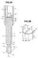
- a glow plug 50 according to a first embodiment of the present invention will be described with reference to FIGS. 1, 2A, 2B, 3 and 4.
- the glow plug 50 has a ceramic heater 1, a metallic sleeve 3 circumferentially surrounding the ceramic heater 1 with a front end portion of the ceramic heater 1 protruded from the metallic sleeve 3, a metallic shell 4 retaining therein a rear end portion of the metallic sleeve 3, a central electrode 6 partly inserted in a rear portion of the metallic shell 4, and leads 16 and 17 for electrically connecting the ceramic heater 1 to the metallic sleeve 3 and the central electrode 6, respectively.
- a threaded mounting portion 5 is formed on an outer circumferential surface of the metallic shell 4 so as to mount the glow plug 1 in a cylinder head (not shown).
- the metallic shell 4 is fixed on the metallic shell 3 by brazing (i.e., filling a space between an inner circumferential surface of the metallic shell 4 and an outer circumferential surface of the metallic sleeve 3 with a brazing filler) or by laser welding an inner front edge of the metallic shell 4 to the outer circumferential surface of the metallic sleeve 3.
- brazing i.e., filling a space between an inner circumferential surface of the metallic shell 4 and an outer circumferential surface of the metallic sleeve 3 with a brazing filler
- the ceramic heater 1 is disposed in the metallic sleeve 3 so that a rear end surface 2r of the heater body 2 is located inside of the metallic sleeve 3 in the first embodiment. Further, a rear end portion of the metallic sleeve 3 is radially protruded so as to make the inside diameter of the rear end portion of the metallic sleeve 3 larger and thereby provide a clearance G between an outer circumferential surface 2s of the heater body 2 and an inner circumferential surface of the rear end portion of the metallic sleeve 3.
- the ceramic heater 1 has a rod-shaped heater body 2 provided with a ceramic substrate 14 and a heating unit 10.
- the heating unit 10 includes a U-shaped heating resistor 11 embedded in a front end portion of the ceramic substrate 14 and a pair of rod-shaped electric conductors 12 and 13 embedded in the ceramic substrate 14 on the rear side of the heating resistor 11.
- the U-shaped heating resistor 11 has a front end portion 11a (i.e. the bottom of U) and rear end portions 11b formed with joint faces 15.
- the front end portion 11a is made smaller in diameter than the rear end portions 11b so that supply current becomes concentrated at the front end portion 11a to heat the front end portion 11a to the highest temperature in a state of working.
- the electric conductors 12 and 13 are generally in parallel along an axis of the glow plug 50, and have front end portions connected to the respective joint faces 15 of the heating resistor 11 and rear end portions exposed at the rear end surface 2r of the heater body 2.
- the ceramic heater 1 further comprises first and second lead-out members 26 and 27 for electrically connecting the exposed rear end portions of the electric conductors 12 and 13 to the leads 16 and 17, respectively.
- the first and second lead-out members 26 and 27 are joined to parts of the rear end surface 2r of the heater body 2 via metallic layers 36 and 37 so as to cover the rear end portions of the conductors 12 and 13, respectively, but not cover the outer circumferential surface 2s of the heater body 2.
- the first and second lead-out members 26 and 27 are insulated from each other. That is, there is no need to provide extra radial space for the first and second lead-out members 26 and 27 so that the glow plug 50 can be made compact in size especially when making the diameter of the heater body 2 smaller. Further, the heater body 2 can be effectively prevented from becoming cracked and split without the outer circumferential surface 2s being intensely acted upon by a large thermal stress even when the glow plug 50 is heated and cooled in cycles.
- each of the first and second lead-out members 26 and 27 is formed into a plate.
- the first lead-out member 26 has a front surface connected via the metallic layer 36 with the rear end surface 2r of the heater body 2 including an exposed surface of the rear end portion of the conductor 12
- the second lead-out member 27 has a front surface connected via the metallic layer 37 with the rear end surface 2r of the heater body 2 including an exposed surface of the rear end portion of the conductor 13.
- first and second lead-out members 26 and 27 are generally semi-circular, being defined by circular edges 26x and 27x and linear edges 26y and 27y, respectively, in the first embodiment.
- the first and second lead-out members 26 and 27 are disposed oppositely to each other so as to provide a predetermined spacing between the linear edges 26y and 27y.
- the spacing is preferably more than or equal to 0.1 mm. Further, the spacing is preferably less than or equal to 1.0 mm in terms of the miniaturization of the glow plug 50. In the first embodiment, the spacing is 0.5 mm.
- the leads 16 and 17 are formed integrally with the first and second lead-out members 26 and 27, respectively, so as to reduce the number of parts.
- the lead 16 and the first lead-out member 26 are formed into one piece so that the lead 16 extends radially from the circular edge 26x of the first lead-out member 26 to cross over the clearance G, and an end portion of the lead 16 is bent axially toward the rear and joined to the inner circumferential surface of the rear end portion of the metallic sleeve 3 by e.g. resistance welding.
- the lead 17 and the second lead-out member 27 are also formed into one piece so that the lead 17 extends axially from the circular edge 27x of the second lead-out member 27, and an rear end portion of the lead 17 is joined to a front end portion of the central electrode 6 by e.g. resistance welding.
- the clearance G is preferably more than or equal to 0.1 mm so that the first lead-out member 26 and the lead 15 can be easily joined to the heater body 2 and the metallic sleeve 3, respectively, and that the lead 17 and the metallic sleeve 3 are assuredly insulated from each other. Also, the clearance G is preferably less than or equal to 1.0 mm in order to make the glow plug 50 compact in size. In the first embodiment, the clearance G is 0.5 mm.
- the ceramic substrate 14 is made of ceramic with an insulation property, and the heating resistor 11 and the electric conductors 12 and 13 are made of ceramic having electrical conductivity. As the entire heater body 2 is made of ceramic, it can be produced with less expenses in time and effort.
- the ceramic for the ceramic substrate 14 can be any insulating ceramic material.
- silicon nitride ceramic is used.
- the silicon nitride ceramic generally contains grains predominantly made of silicon nitride (Si 3 N 4 ) bonded to each other through grain boundary resulting from a sintering aid.
- the silicon nitride may contain Al and O with which some of Si and N are substituted, respectively.
- the grains may contain a metal atom or atoms, such as Li, Ca, Mg and/or Y, in the silicon nitride as a solid solution.
- the sintering aid includes a cationic element or elements selected from Groups 3A, 4A, 5A, 3B (e.g. Al) and 4B (e.g.
- the above cationic element and elements are added in the form of oxide, and contained in the form of oxide or compound oxide (such as silicate) in the sintered silicon nitride ceramic.
- the amount of the sintering aid is from 1 to 10% by weight in terms of oxide based on the total weight of the sintered silicon nitride ceramic. When the amount of the sintering aid is less than 1% by weight, the ceramic material cannot be close-grained when sintered. On the other hand, when the amount of the sintering aid is more than 10% by weight, the obtained ceramic material cannot attain a sufficient strength, toughness and/or heat resistance. Preferably, the amount of the sintering aid is from 2 to 8% by weight.
- the sintering aid includes rare-earth element or elements
- rare-earth element or elements there may be selected from Sc, Y, La, Ce, Pr, Nd, Sm, Eu, Gd, Tb, Dy, Ho, Er, Tm, Yb and Lu.
- the ceramic for the heating resistor 11 (hereinafter referred to as "first ceramic") has a higher electrical resistance than the ceramic for the conductors 12 and 13 (referred to as “second ceramic").
- the method for providing the first and second ceramic with different electrical resistances is not particularly restricted. For example, there may be used:
- the same insulating ceramic material as used for the ceramic substrate 14 can be added to the first and second ceramic.
- the electrical resistances of the first and second ceramic can be adjusted depending on the contents of the insulating ceramic material and of the conductive ceramic material. More specifically, the first ceramic for the heating resistor 11 comprises 10 to 25% by volume of the conductive ceramic material and the balance being the insulating ceramic material. When the amount of the conductive ceramic material is more than 25% by volume, the conductivity of the first ceramic becomes too high so that the heating resistor 11 cannot generate sufficient heat. When the amount of the conductive ceramic material is less than 10% by volume, the conductivity of the first ceramic becomes too low so that the heating resistor 11 cannot generate sufficient heat. Further, the second ceramic for the conductors 12 and 13 comprises 15 to 30% by volume of the conductive ceramic material and the balance being the insulating ceramic material.
- the second ceramic cannot be close-grained when sintered and therefore does not have sufficient strength.
- the electrical resistance of the second ceramic does not rise sufficiently even when heated to a normal working temperature for the preheating of an engine, thereby failing to perform a self-control function to stabilize its current density.
- the amount of the conductive ceramic material is less than 15% by volume, the electric conductors 12 and 13 generate heat, thereby deteriorating heat-generating efficiency of the heating resistor 11.
- the first ceramic comprises 16% by volume (55% by weight) of tungsten carbide and the balance being silicon nitride ceramic
- the second ceramic comprises 20% by volume (70% by weight) of tungsten carbide and the balance being silicon nitride ceramic.
- a pair of electric conductors 51 and 52 formed as lead wires of high-melting metal may be employed in place of the ceramic conductors 12 and 13, as shown in FIG. 4.
- high-melting metal such as tungsten or the like
- electromigration there arises a possibility of electromigration by which the metal atoms of the conductors 51 and 52 are diffused under the electrochemical force resulting from field gradients. The effect of electromigration can be substantially avoided by the use of the ceramic conductors 12 and 13.
- the first and second lead-out members 26 and 27 are joined to the rear end surface 2r of the heater body 2 via the metallic layers 36 and 37, respectively, as described above.
- Such metallic layers 36 and 37 can be formed by brazing with an activated brazing material containing therein an active metal component, or by metallizing the heater body 2 by evaporation of an active metal component and then brazing with normal brazing materials.
- the brazing material can be any conventional Ag- or Cu-based brazing material, and the active metal component may includes at least one of Ti, Zr and Hf.
- a Cu-based activated brazing material comprising 5% by weight of Si, 3% by weight of Pd, 2% by weight of Ti and the balance being Cu may be used for the metallic layers 36 and 37.
- the metallic layers 36 and 37 are preferably formed by screen printing, so that the metallic layers 36 and 37 can be at proper positions on the rear end surface 2r of the heater body 2 while being prevented from hanging over the outer circumferential surface 2s of the heater body 2.
- the ceramic-metal joint there is a great difference in coefficients of linear expansion between the heater body 2 and the metallic layers 36 and 37. As a result, the ceramic-metal joint between the heater body 2 and the metallic layers 36 and 37 is liable to be acted upon by a large thermal stress when the joint is cooled after formed by brazing and when the joint is heated and cooled in cycles through the use of the glow plug 50.
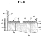
- the first and second lead-out members 26 and 27 may have low-expansion metal layers 62 formed at least in parts of rear surfaces thereof so as to radially correspond in position to the metallic layers 36 and 37, while the front surfaces thereof are kept in contact with the metallic layers 36 and 37, respectively, as shown in FIG. 3.
- the first lead-out member 26 and the lead 16 are formed into one piece of a clad material having the low-expansion metal layer 62
- the second lead-out member 27 and the lead 17 are formed into one piece of a clad material having the low-expansion metal layer 62 in the first embodiment.
- the low-expansion metal layers 62 are made of a metal having a lower coefficient of expansion than that of the brazing material for the metallic layers 36 and 37, so as to provide the effects of limiting substantial expansion and contraction of the metallic layers 36 and 37 and absorbing the thermal stress exerted on the ceramic-metal joint between the heater body 2 and the metallic layers 36 and 37. This makes it possible to increase the durability of the ceramic-metal joint. More specifically, the low-expansion metal layer 62 can be made of a Fe-based low-expansion metal having an average coefficient of linear expansion lower than or equal to 2.0 ⁇ 10 -6 /°C at 100 to 200°C.
- Such a low-expansion metal include Fe alloys (with a Fe content of 40% by weight or more) having very small coefficients of expansion under so-called Invar effect.
- Invar effect is a phenomenon in which, when ferromagnetism (including antiferromagnetism) occurs at room temperature to cause the expansion of a material, such expansion cancels out volume change resulting from lattice vibration so that the coefficient of linear expansion of the material is made small.
- the Fe alloy remarkably exhibits such an effect when containing specific contents of Ni, Co, Pd and/or Pt as alloy elements.
- at least one of Ni and Co is contained in view of cost reduction.
- the alloy may not exhibit a low coefficient of linear expansion when the first and second lead-out members 26 and 27 are at the highest temperature (e.g. 700 to 900°C) in a state of working, but always has a very small coefficient of linear expansion at a temperature lower than or equal to a magnetic transformation point thereof.
- the alloy exhibits thermal hysteresis, displacements of the low-expansion metal layer 62 between its expansion state and contract state can be made smaller.
- an alloy having a higher magnetic transformation point e.g. 60°C or higher
- an alloy having a higher magnetic transformation point e.g. 60°C or higher
- first and second lead-out members 26 and 27 may have soft metal layers 61 formed in at least parts of the front surfaces thereof so as to be kept in contact with the metallic layers 36 and 37, as shown in FIG. 3.
- the soft metal layers 61 and the low-expansion metal layers 62 are clad with each other so as to take on a two-layered clad structure throughout the first and second lead-out members 26 and 27 and the leads 16 and 17.
- the soft metal layers 61 are made of a metal softer than the metal for the low-expansion metal layers 62, such as Cu or Cu alloy. Even when the metallic layers 36 and 37 are displaced relative to the heater body 2 due to the difference in coefficients of linear expansion therebetween, the soft metal layers 61 get plastically deformed. This makes it possible to absorb the thermal stress exerted on the ceramic-metal joint and thereby prevent the separation of the metallic layers 36 and 37 from the heater body 2.
- the central electrode 6 is disposed in the metallic shell 4 with a ceramic ring 31 interposed between the inner circumferential surface of the metallic shell 4 and the outer circumferential surface of the rear end portion of the central electrode 6, whereby an electrical insulation between the metallic shell 4 and the central electrode 6 can be maintained.
- a protruded head portion 31a is formed on the outer circumferential surface of the ceramic ring 31, and retained by a stepped portion 4e of the metallic shell 4 so that the ceramic ring 31 does not slip off from the front side.
- a glass seal layer 32 is formed so as to hold the ceramic ring 31 from the rear side.
- An outer circumferential portion of the central electrode 6 (the shaded portion of FIG. 1) which contacts with the glass seal member 32 is roughened by e.
- a rear end portion of the central electrode 6 is protruded from the metallic shell 4, and a metallic terminal member 7 is fit onto the protruded end portion of the central electrode 6 with an insulating bushing 8 retained by a rear end face of the metallic shell 4, and then, connected to a battery (not shown).
- the terminal member 7 is fixed to the central electrode 6 by caulking at a caulked portion 9 so as to make an electrical connection between the central electrode 6 and the terminal member 7.
- the glow plug 50 is mounted in the cylinder head of the engine by means of the threaded mounting portion 5 so that the front end portion (i.e. the heating end portion) of the heater body 2 is positioned in e.g. a swirl chamber (which is connected to a combustion chamber of the engine).
- a swirl chamber which is connected to a combustion chamber of the engine.
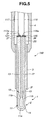
- a glow plug 150 according to a second embodiment of the present invention will be described with reference to FIGS. 5, 6A, 6B, 7 and 8.
- the second embodiment is similar in structure to the first embodiment, except that the ceramic heater 1 is grounded without passing through the metallic sleeve 3 and the metallic sleeve 4 and that leads 116 and 117 are formed separately from first and second lead-out members 126 and 127, respectively.
- the ceramic heater 1 is disposed in the metallic sleeve 3 with both the front and rear end portions thereof protruded from the metallic sleeve 3.
- the first and second lead-out members 126 and 127 are plate-shaped and joined at front surfaces thereof to the rear end surface 2r of the heater body 2 via the metallic layers 36 and 37 so as to cover the exposed rear end portions of the electric conductors 12 and 13, respectively, but not to cover the outer circumferential surface 2s of the heater body 2. Further, front end portions 116a and 117a of the leads 116 and 117 are bent and joined to the rear surfaces of the first and second lead-out members 126 and 127 by e.g. resistance welding, as shown in FIG. 6A, in the second embodiment.
- the remaining portions of the leads 116 and 117 extend axially toward the rear and are joined at rear end portions thereof to terminal members (not shown in FIG. 5) fitted onto a rear end portion of the metallic shell 4.
- the heating resistor 11 of the heater body 2 is energized and grounded through the terminal members, the leads 116 and 117 and the first and second lead-out members 126 and 127, while the metallic shell 4 retains therein the ceramic heater 1 in a state of being insulated from the metallic shell 4.
- the first and second lead-out members 126 and 127 may be made of a clad material having the soft metal layer 61 and the low-expansion metal layer 62.
- first and second lead-out members 126 and 127 are generally semi-circular, being defined by circular edges 126x and 127x and linear edges 126y and 127y, respectively.
- the first and second lead-out members 126 and 127 are disposed oppositely to each other so as to provide a predetermined spacing between the linear edges 126y and 127y.
- the front end portions 116a and 117b of the leads 116 and 117 are welded at sides thereof to the first and second lead-out members 126 and 127 so that the front end portions 116a and 117b are orthogonal to the linear edges 126y and 127y, respectively.
- each of the first and second lead-out members 126 and 127 may not be brazed to the heater body 2 at a high strength even when the activated brazing material is used. If parts of the bent front end portions 116a and 117a of the leads 116 and 117 are protruded from the outer edges 126x and 126y of the first and second lead-out members 126 and 127, the tensions exerted on the leads 116 and 117 cause the front end portions 116a and 117a to peel the first and second lead-out members 126 and 127 gradually from the heater body 2. As a result, the first and second lead-out members 126 and 127 become likely to be separated from the heater body 2.
- the front end portions 116a and 117a of the leads 116 and 117 are preferably joined to the first and second lead-out members 126 and 127 so that the front end portions 116a and 117a are entirely placed on the rear surfaces of the first and second lead-out members 126 and 127 as shown in FIG. 6B. More preferably, the front end portions 116a and 117a of the leads 116 and 117 are joined at welds W to the first and second lead-out members 126 and 127, respectively, so that the inside bends of the leads 116 and 117 are at the shortest distances d of 0.3 or more from the outer edges 126x and 127x of the lead-out members 126 and 127.
- the bent front end portions 116a and 117a of the leads 116 and 117 may be joined to the first and second lead-out members 126 and 127 so that the front end portions 116a and 117a are generally in parallel with the linear edges 126y and 127y, respectively, as shown in FIG. 7.
- This makes it possible to secure larger joint surfaces between the lead 116 and the first lead-out member 126 and between the lead 117 and the second lead-out member 127 and thereby possible to increase joint strengths therebetween.
- the front end portions 116a and 117a of the leads 116 and 117 may be joined without being bent.
- the first end portions 116a and 117a of the leads 116 and 117 are preferably welded to the centers of the first and second lead-out members 126 and 127, respectively, as shown in FIG. 8, such that the first and second lead-out members 126 and 127 can be prevented from separating gradually from the rear end face 2r of the heater body 2.
- the first and second lead-out members 126 and 127 may be formed into a single plate by e.g. punching. In such a case, the first and second lead-out members 126 and 127 are joined simultaneously to the heater body 2 in a state of being held together as a single plate . Then, the first and second lead-out members 126 and 127 are separated from each other by removing linking parts between the first and second lead-out members 126 and 127 by mechanical means (such as punching).
Landscapes
- Engineering & Computer Science (AREA)
- Chemical & Material Sciences (AREA)
- Combustion & Propulsion (AREA)
- Mechanical Engineering (AREA)
- General Engineering & Computer Science (AREA)
- Ceramic Engineering (AREA)
- Resistance Heating (AREA)
Applications Claiming Priority (2)
| Application Number | Priority Date | Filing Date | Title |
|---|---|---|---|
| JP2001258302A JP4553529B2 (ja) | 2001-08-28 | 2001-08-28 | セラミックヒータ及びそれを用いたグロープラグ |
| JP2001258302 | 2001-08-28 |
Publications (3)
| Publication Number | Publication Date |
|---|---|
| EP1288572A2 true EP1288572A2 (fr) | 2003-03-05 |
| EP1288572A3 EP1288572A3 (fr) | 2006-09-20 |
| EP1288572B1 EP1288572B1 (fr) | 2008-03-26 |
Family
ID=19085850
Family Applications (1)
| Application Number | Title | Priority Date | Filing Date |
|---|---|---|---|
| EP02016925A Expired - Lifetime EP1288572B1 (fr) | 2001-08-28 | 2002-07-31 | Elément chauffant céramique, et bougie à incandescence comportant cet élément |
Country Status (4)
| Country | Link |
|---|---|
| US (1) | US6737612B2 (fr) |
| EP (1) | EP1288572B1 (fr) |
| JP (1) | JP4553529B2 (fr) |
| DE (1) | DE60225769T2 (fr) |
Cited By (2)
| Publication number | Priority date | Publication date | Assignee | Title |
|---|---|---|---|---|
| US20100288747A1 (en) * | 2007-10-29 | 2010-11-18 | Kyocera Corporation | Ceramic heater and glow plug provided therewith |
| US20110114622A1 (en) * | 2008-02-20 | 2011-05-19 | Ngk Spark Plug Co., Ltd. | Ceramic heater and glow plug |
Families Citing this family (14)
| Publication number | Priority date | Publication date | Assignee | Title |
|---|---|---|---|---|
| US7034253B2 (en) * | 2003-04-07 | 2006-04-25 | Ngk Spark Plug Co., Ltd. | Ceramic heater with ring member electrically connecting the heater to lead terminal core rod |
| DE102006016566B4 (de) * | 2005-09-22 | 2008-06-12 | Beru Ag | Zusammengesetzter Leiter, insbesondere für Glühkerzen für Dieselmotoren |
| US7626141B2 (en) * | 2006-03-20 | 2009-12-01 | Surface Igniter Llc | Mounting device gas igniter |
| KR101195918B1 (ko) * | 2008-01-29 | 2012-10-30 | 쿄세라 코포레이션 | 세라믹 히터 및 글로우 플러그 |
| US20100078421A1 (en) * | 2008-10-01 | 2010-04-01 | Federal-Mogul Italy Sr1 | Glow plug adn heater assembly therefor with an improved connection between a central electrode and a heater probe of the heater assembly |
| KR100963224B1 (ko) * | 2009-02-03 | 2010-06-10 | (주) 더몰론코리아 | 물 또는 공기 중에서 겸용 사용이 가능한 세라믹 코팅 히터 |
| JP5701979B2 (ja) | 2011-04-27 | 2015-04-15 | 京セラ株式会社 | ヒータおよびこれを備えたグロープラグ |
| JP5751968B2 (ja) * | 2011-07-25 | 2015-07-22 | 京セラ株式会社 | ヒータおよびこれを備えたグロープラグ |
| EP3124867A4 (fr) * | 2014-03-27 | 2017-06-21 | Bosch Corporation | Bougie à incandescence du type à élément chauffant en céramique |
| DE102016114929B4 (de) * | 2016-08-11 | 2018-05-09 | Borgwarner Ludwigsburg Gmbh | Druckmessglühkerze |
| WO2018159687A1 (fr) * | 2017-03-02 | 2018-09-07 | 日本碍子株式会社 | Dispositif de chauffage de tranche |
| CN207869432U (zh) * | 2018-03-07 | 2018-09-14 | 东莞市国研电热材料有限公司 | 一种多温区陶瓷发热体 |
| WO2020067508A1 (fr) * | 2018-09-28 | 2020-04-02 | 京セラ株式会社 | Élément chauffant et bougie de préchauffage le comportant |
| CN113700586A (zh) * | 2021-09-29 | 2021-11-26 | 重庆利迈陶瓷技术有限公司 | 一种陶瓷电热塞 |
Citations (5)
| Publication number | Priority date | Publication date | Assignee | Title |
|---|---|---|---|---|
| JPS62141423A (ja) | 1985-12-13 | 1987-06-24 | Jidosha Kiki Co Ltd | デイ−ゼルエンジン用グロ−プラグ |
| JPH04268112A (ja) | 1991-02-20 | 1992-09-24 | Jidosha Kiki Co Ltd | セラミックヒータ型グロープラグ |
| JPH0630608A (ja) | 1992-07-17 | 1994-02-08 | Iseki & Co Ltd | 田植機 |
| JPH10205753A (ja) | 1996-11-19 | 1998-08-04 | Ngk Spark Plug Co Ltd | セラミックグロープラグ |
| JP2000356343A (ja) | 1999-06-16 | 2000-12-26 | Bosch Braking Systems Co Ltd | セラミックヒータ型グロープラグ |
Family Cites Families (14)
| Publication number | Priority date | Publication date | Assignee | Title |
|---|---|---|---|---|
| US4418661A (en) * | 1981-02-07 | 1983-12-06 | Robert Bosch Gmbh | Glow plug, particularly for diesel engine |
| JPS58119051U (ja) * | 1982-01-30 | 1983-08-13 | いすゞ自動車株式会社 | グロ−プラグ |
| JPS60114629A (ja) * | 1983-11-28 | 1985-06-21 | Jidosha Kiki Co Ltd | デイ−ゼルエンジン用グロ−プラグ |
| JPS60165682U (ja) * | 1984-04-12 | 1985-11-02 | 日本特殊陶業株式会社 | 両絶縁型セラミツクグロ−プラグ |
| JPS60254586A (ja) * | 1984-05-30 | 1985-12-16 | 株式会社デンソー | セラミツクヒ−タ |
| JPH0648408Y2 (ja) * | 1986-03-05 | 1994-12-12 | 日本碍子株式会社 | 加熱器付酸素センサ |
| JPS6391432A (ja) * | 1986-10-03 | 1988-04-22 | Jidosha Kiki Co Ltd | デイ−ゼルエンジン用グロ−プラグの製造方法 |
| JPH03175210A (ja) * | 1989-09-11 | 1991-07-30 | Jidosha Kiki Co Ltd | セラミツクヒータ型グロープラグ |
| JPH0432616A (ja) * | 1990-05-28 | 1992-02-04 | Hitachi Metals Ltd | ディーゼルエンジン用グロープラグ |
| JP3044630B2 (ja) * | 1991-02-06 | 2000-05-22 | ボッシュ ブレーキ システム株式会社 | セラミックヒータ型グロープラグ |
| JP2899197B2 (ja) * | 1993-09-14 | 1999-06-02 | シャープ株式会社 | セラミックヒータのリード端子接続装置 |
| JP3785699B2 (ja) * | 1996-09-18 | 2006-06-14 | 株式会社デンソー | グロープラグ |
| JPH10300085A (ja) * | 1997-04-22 | 1998-11-13 | Ngk Spark Plug Co Ltd | セラミックヒータおよびセラミックグロープラグ |
| JP2002270339A (ja) * | 2001-03-08 | 2002-09-20 | Ngk Spark Plug Co Ltd | セラミックヒーター |
-
2001
- 2001-08-28 JP JP2001258302A patent/JP4553529B2/ja not_active Expired - Fee Related
-
2002
- 2002-07-31 DE DE60225769T patent/DE60225769T2/de not_active Expired - Lifetime
- 2002-07-31 EP EP02016925A patent/EP1288572B1/fr not_active Expired - Lifetime
- 2002-08-01 US US10/208,797 patent/US6737612B2/en not_active Expired - Fee Related
Patent Citations (5)
| Publication number | Priority date | Publication date | Assignee | Title |
|---|---|---|---|---|
| JPS62141423A (ja) | 1985-12-13 | 1987-06-24 | Jidosha Kiki Co Ltd | デイ−ゼルエンジン用グロ−プラグ |
| JPH04268112A (ja) | 1991-02-20 | 1992-09-24 | Jidosha Kiki Co Ltd | セラミックヒータ型グロープラグ |
| JPH0630608A (ja) | 1992-07-17 | 1994-02-08 | Iseki & Co Ltd | 田植機 |
| JPH10205753A (ja) | 1996-11-19 | 1998-08-04 | Ngk Spark Plug Co Ltd | セラミックグロープラグ |
| JP2000356343A (ja) | 1999-06-16 | 2000-12-26 | Bosch Braking Systems Co Ltd | セラミックヒータ型グロープラグ |
Cited By (3)
| Publication number | Priority date | Publication date | Assignee | Title |
|---|---|---|---|---|
| US20100288747A1 (en) * | 2007-10-29 | 2010-11-18 | Kyocera Corporation | Ceramic heater and glow plug provided therewith |
| US20110114622A1 (en) * | 2008-02-20 | 2011-05-19 | Ngk Spark Plug Co., Ltd. | Ceramic heater and glow plug |
| US8378273B2 (en) * | 2008-02-20 | 2013-02-19 | Ngk Spark Plug Co., Ltd. | Ceramic heater and glow plug |
Also Published As
| Publication number | Publication date |
|---|---|
| EP1288572B1 (fr) | 2008-03-26 |
| DE60225769T2 (de) | 2008-07-17 |
| EP1288572A3 (fr) | 2006-09-20 |
| US20030042243A1 (en) | 2003-03-06 |
| DE60225769D1 (de) | 2008-05-08 |
| JP4553529B2 (ja) | 2010-09-29 |
| US6737612B2 (en) | 2004-05-18 |
| JP2003068428A (ja) | 2003-03-07 |
Similar Documents
| Publication | Publication Date | Title |
|---|---|---|
| EP1288572B1 (fr) | Elément chauffant céramique, et bougie à incandescence comportant cet élément | |
| US8552343B2 (en) | Brazing structure, ceramic heater, and glow plug | |
| JP3816073B2 (ja) | グロープラグ及びグロープラグの製造方法 | |
| EP1288573B1 (fr) | Bougie à incandescence | |
| JPS60254586A (ja) | セラミツクヒ−タ | |
| JPS62252829A (ja) | デイ−ゼルエンジン用グロ−プラグ | |
| JP2002270339A (ja) | セラミックヒーター | |
| JP4677140B2 (ja) | グロープラグ | |
| JP3886699B2 (ja) | グロープラグ及びその製造方法 | |
| JP4562315B2 (ja) | セラミックヒータ、セラミックヒータの製造方法及びグロープラグ | |
| JP3601079B2 (ja) | セラミックヒータ | |
| JP3594660B2 (ja) | セラミックヒータ | |
| JP2002333136A (ja) | グロープラグ | |
| JP4672910B2 (ja) | グロープラグの製造方法 | |
| JP2000021556A (ja) | セラミックヒータ | |
| JP2003166714A (ja) | グロープラグ及びグロープラグの製造方法 | |
| JP4019004B2 (ja) | セラミックヒータ及びそれを用いたグロープラグ | |
| CN115399067A (zh) | 加热器 | |
| JPH10335049A (ja) | セラミックヒータ | |
| JP2002333137A (ja) | グロープラグ | |
| JP2000220829A (ja) | セラミックヒ―タ型グロ―プラグおよびその製造方法 | |
| EP3113575B1 (fr) | Dispositif de chauffage et bougie de préchauffage | |
| JP4596684B2 (ja) | グロープラグ | |
| JP2002349853A (ja) | グロープラグ | |
| JPH0439195B2 (fr) |
Legal Events
| Date | Code | Title | Description |
|---|---|---|---|
| PUAI | Public reference made under article 153(3) epc to a published international application that has entered the european phase |
Free format text: ORIGINAL CODE: 0009012 |
|
| AK | Designated contracting states |
Kind code of ref document: A2 Designated state(s): AT BE BG CH CY CZ DE DK EE ES FI FR GB GR IE IT LI LU MC NL PT SE SK TR |
|
| AX | Request for extension of the european patent |
Extension state: AL LT LV MK RO SI |
|
| PUAL | Search report despatched |
Free format text: ORIGINAL CODE: 0009013 |
|
| AK | Designated contracting states |
Kind code of ref document: A3 Designated state(s): AT BE BG CH CY CZ DE DK EE ES FI FR GB GR IE IT LI LU MC NL PT SE SK TR |
|
| AX | Request for extension of the european patent |
Extension state: AL LT LV MK RO SI |
|
| 17P | Request for examination filed |
Effective date: 20061004 |
|
| GRAP | Despatch of communication of intention to grant a patent |
Free format text: ORIGINAL CODE: EPIDOSNIGR1 |
|
| AKX | Designation fees paid |
Designated state(s): DE FR GB IT |
|
| GRAS | Grant fee paid |
Free format text: ORIGINAL CODE: EPIDOSNIGR3 |
|
| GRAA | (expected) grant |
Free format text: ORIGINAL CODE: 0009210 |
|
| AK | Designated contracting states |
Kind code of ref document: B1 Designated state(s): DE FR GB IT |
|
| REG | Reference to a national code |
Ref country code: GB Ref legal event code: FG4D |
|
| REF | Corresponds to: |
Ref document number: 60225769 Country of ref document: DE Date of ref document: 20080508 Kind code of ref document: P |
|
| EN | Fr: translation not filed | ||
| PLBE | No opposition filed within time limit |
Free format text: ORIGINAL CODE: 0009261 |
|
| STAA | Information on the status of an ep patent application or granted ep patent |
Free format text: STATUS: NO OPPOSITION FILED WITHIN TIME LIMIT |
|
| 26N | No opposition filed |
Effective date: 20081230 |
|
| GBPC | Gb: european patent ceased through non-payment of renewal fee |
Effective date: 20080731 |
|
| PG25 | Lapsed in a contracting state [announced via postgrant information from national office to epo] |
Ref country code: FR Free format text: LAPSE BECAUSE OF FAILURE TO SUBMIT A TRANSLATION OF THE DESCRIPTION OR TO PAY THE FEE WITHIN THE PRESCRIBED TIME-LIMIT Effective date: 20090116 |
|
| PG25 | Lapsed in a contracting state [announced via postgrant information from national office to epo] |
Ref country code: GB Free format text: LAPSE BECAUSE OF NON-PAYMENT OF DUE FEES Effective date: 20080731 |
|
| PG25 | Lapsed in a contracting state [announced via postgrant information from national office to epo] |
Ref country code: IT Free format text: LAPSE BECAUSE OF FAILURE TO SUBMIT A TRANSLATION OF THE DESCRIPTION OR TO PAY THE FEE WITHIN THE PRESCRIBED TIME-LIMIT Effective date: 20080326 |
|
| PGFP | Annual fee paid to national office [announced via postgrant information from national office to epo] |
Ref country code: DE Payment date: 20190716 Year of fee payment: 18 |
|
| REG | Reference to a national code |
Ref country code: DE Ref legal event code: R119 Ref document number: 60225769 Country of ref document: DE |
|
| PG25 | Lapsed in a contracting state [announced via postgrant information from national office to epo] |
Ref country code: DE Free format text: LAPSE BECAUSE OF NON-PAYMENT OF DUE FEES Effective date: 20210202 |