EP1288351A2 - Kohlenstofffaser, Elektrodenmaterial für Lithium-Sekundärbatterie und Lithium-Sekundärbatterie - Google Patents
Kohlenstofffaser, Elektrodenmaterial für Lithium-Sekundärbatterie und Lithium-Sekundärbatterie Download PDFInfo
- Publication number
- EP1288351A2 EP1288351A2 EP02006393A EP02006393A EP1288351A2 EP 1288351 A2 EP1288351 A2 EP 1288351A2 EP 02006393 A EP02006393 A EP 02006393A EP 02006393 A EP02006393 A EP 02006393A EP 1288351 A2 EP1288351 A2 EP 1288351A2
- Authority
- EP
- European Patent Office
- Prior art keywords
- carbon fiber
- layers
- carbon
- hexagonal
- secondary battery
- Prior art date
- Legal status (The legal status is an assumption and is not a legal conclusion. Google has not performed a legal analysis and makes no representation as to the accuracy of the status listed.)
- Granted
Links
- 229920000049 Carbon (fiber) Polymers 0.000 title claims abstract description 136
- 239000004917 carbon fiber Substances 0.000 title claims abstract description 136
- VNWKTOKETHGBQD-UHFFFAOYSA-N methane Chemical compound C VNWKTOKETHGBQD-UHFFFAOYSA-N 0.000 title claims abstract description 129
- 239000007772 electrode material Substances 0.000 title claims abstract description 27
- 229910052744 lithium Inorganic materials 0.000 title claims description 32
- WHXSMMKQMYFTQS-UHFFFAOYSA-N Lithium Chemical compound [Li] WHXSMMKQMYFTQS-UHFFFAOYSA-N 0.000 title claims description 31
- OKTJSMMVPCPJKN-UHFFFAOYSA-N Carbon Chemical compound [C] OKTJSMMVPCPJKN-UHFFFAOYSA-N 0.000 claims abstract description 118
- 229910052799 carbon Inorganic materials 0.000 claims abstract description 91
- ZOXJGFHDIHLPTG-UHFFFAOYSA-N Boron Chemical group [B] ZOXJGFHDIHLPTG-UHFFFAOYSA-N 0.000 claims abstract description 16
- 229910021389 graphene Inorganic materials 0.000 claims abstract description 16
- 125000004432 carbon atom Chemical group C* 0.000 claims abstract description 4
- 238000010438 heat treatment Methods 0.000 claims description 17
- 238000001237 Raman spectrum Methods 0.000 claims description 9
- 125000004429 atom Chemical group 0.000 claims description 9
- 238000005087 graphitization Methods 0.000 claims description 5
- 230000001788 irregular Effects 0.000 claims description 5
- 230000008034 disappearance Effects 0.000 claims 1
- 230000002787 reinforcement Effects 0.000 abstract description 2
- 239000010410 layer Substances 0.000 description 118
- HBBGRARXTFLTSG-UHFFFAOYSA-N Lithium ion Chemical compound [Li+] HBBGRARXTFLTSG-UHFFFAOYSA-N 0.000 description 26
- 229910001416 lithium ion Inorganic materials 0.000 description 26
- 239000000835 fiber Substances 0.000 description 20
- 229910002804 graphite Inorganic materials 0.000 description 11
- 239000010439 graphite Substances 0.000 description 11
- 239000011230 binding agent Substances 0.000 description 10
- 238000009830 intercalation Methods 0.000 description 9
- 230000002687 intercalation Effects 0.000 description 9
- 239000010405 anode material Substances 0.000 description 8
- 239000003792 electrolyte Substances 0.000 description 8
- XLYOFNOQVPJJNP-UHFFFAOYSA-N water Substances O XLYOFNOQVPJJNP-UHFFFAOYSA-N 0.000 description 7
- 238000003917 TEM image Methods 0.000 description 6
- 239000000654 additive Substances 0.000 description 6
- 230000000996 additive effect Effects 0.000 description 6
- 229910052796 boron Inorganic materials 0.000 description 5
- 239000013078 crystal Substances 0.000 description 5
- 230000000694 effects Effects 0.000 description 5
- 239000004570 mortar (masonry) Substances 0.000 description 5
- IJGRMHOSHXDMSA-UHFFFAOYSA-N Atomic nitrogen Chemical compound N#N IJGRMHOSHXDMSA-UHFFFAOYSA-N 0.000 description 4
- 238000000498 ball milling Methods 0.000 description 4
- 230000003247 decreasing effect Effects 0.000 description 4
- 238000000227 grinding Methods 0.000 description 4
- 238000000034 method Methods 0.000 description 4
- 238000001000 micrograph Methods 0.000 description 4
- UHOVQNZJYSORNB-UHFFFAOYSA-N Benzene Chemical compound C1=CC=CC=C1 UHOVQNZJYSORNB-UHFFFAOYSA-N 0.000 description 3
- 239000003054 catalyst Substances 0.000 description 3
- 238000006243 chemical reaction Methods 0.000 description 3
- 150000001875 compounds Chemical class 0.000 description 3
- 238000009826 distribution Methods 0.000 description 3
- 239000011888 foil Substances 0.000 description 3
- 239000007788 liquid Substances 0.000 description 3
- 239000000463 material Substances 0.000 description 3
- 239000005518 polymer electrolyte Substances 0.000 description 3
- 229920005989 resin Polymers 0.000 description 3
- 239000011347 resin Substances 0.000 description 3
- AZQWKYJCGOJGHM-UHFFFAOYSA-N 1,4-benzoquinone Chemical compound O=C1C=CC(=O)C=C1 AZQWKYJCGOJGHM-UHFFFAOYSA-N 0.000 description 2
- XKRFYHLGVUSROY-UHFFFAOYSA-N Argon Chemical compound [Ar] XKRFYHLGVUSROY-UHFFFAOYSA-N 0.000 description 2
- RYGMFSIKBFXOCR-UHFFFAOYSA-N Copper Chemical compound [Cu] RYGMFSIKBFXOCR-UHFFFAOYSA-N 0.000 description 2
- VEXZGXHMUGYJMC-UHFFFAOYSA-N Hydrochloric acid Chemical compound Cl VEXZGXHMUGYJMC-UHFFFAOYSA-N 0.000 description 2
- QAOWNCQODCNURD-UHFFFAOYSA-N Sulfuric acid Chemical compound OS(O)(=O)=O QAOWNCQODCNURD-UHFFFAOYSA-N 0.000 description 2
- PNEYBMLMFCGWSK-UHFFFAOYSA-N aluminium oxide Inorganic materials [O-2].[O-2].[O-2].[Al+3].[Al+3] PNEYBMLMFCGWSK-UHFFFAOYSA-N 0.000 description 2
- 229910003481 amorphous carbon Inorganic materials 0.000 description 2
- QVGXLLKOCUKJST-UHFFFAOYSA-N atomic oxygen Chemical compound [O] QVGXLLKOCUKJST-UHFFFAOYSA-N 0.000 description 2
- 238000004364 calculation method Methods 0.000 description 2
- 239000010406 cathode material Substances 0.000 description 2
- 239000011889 copper foil Substances 0.000 description 2
- 125000004122 cyclic group Chemical group 0.000 description 2
- 238000009831 deintercalation Methods 0.000 description 2
- 125000000524 functional group Chemical group 0.000 description 2
- 239000011244 liquid electrolyte Substances 0.000 description 2
- 238000004519 manufacturing process Methods 0.000 description 2
- 229910052757 nitrogen Inorganic materials 0.000 description 2
- 239000001301 oxygen Substances 0.000 description 2
- 229910052760 oxygen Inorganic materials 0.000 description 2
- 239000002245 particle Substances 0.000 description 2
- 239000002296 pyrolytic carbon Substances 0.000 description 2
- 239000002994 raw material Substances 0.000 description 2
- 239000002904 solvent Substances 0.000 description 2
- 238000005406 washing Methods 0.000 description 2
- UFHFLCQGNIYNRP-UHFFFAOYSA-N Hydrogen Chemical compound [H][H] UFHFLCQGNIYNRP-UHFFFAOYSA-N 0.000 description 1
- 229910032387 LiCoO2 Inorganic materials 0.000 description 1
- 229910003005 LiNiO2 Inorganic materials 0.000 description 1
- 229910002097 Lithium manganese(III,IV) oxide Inorganic materials 0.000 description 1
- 239000004809 Teflon Substances 0.000 description 1
- 229920006362 Teflon® Polymers 0.000 description 1
- 238000005411 Van der Waals force Methods 0.000 description 1
- 238000002441 X-ray diffraction Methods 0.000 description 1
- 230000002411 adverse Effects 0.000 description 1
- 229910052782 aluminium Inorganic materials 0.000 description 1
- XAGFODPZIPBFFR-UHFFFAOYSA-N aluminium Chemical compound [Al] XAGFODPZIPBFFR-UHFFFAOYSA-N 0.000 description 1
- 229910052786 argon Inorganic materials 0.000 description 1
- 150000001721 carbon Chemical group 0.000 description 1
- 239000002134 carbon nanofiber Substances 0.000 description 1
- 239000002041 carbon nanotube Substances 0.000 description 1
- 229910021393 carbon nanotube Inorganic materials 0.000 description 1
- 239000003575 carbonaceous material Substances 0.000 description 1
- 125000002915 carbonyl group Chemical group [*:2]C([*:1])=O 0.000 description 1
- 125000003178 carboxy group Chemical group [H]OC(*)=O 0.000 description 1
- 239000002131 composite material Substances 0.000 description 1
- 230000008602 contraction Effects 0.000 description 1
- 230000006866 deterioration Effects 0.000 description 1
- JKWMSGQKBLHBQQ-UHFFFAOYSA-N diboron trioxide Chemical compound O=BOB=O JKWMSGQKBLHBQQ-UHFFFAOYSA-N 0.000 description 1
- 238000007599 discharging Methods 0.000 description 1
- 239000012153 distilled water Substances 0.000 description 1
- 238000001035 drying Methods 0.000 description 1
- 239000003822 epoxy resin Substances 0.000 description 1
- KTWOOEGAPBSYNW-UHFFFAOYSA-N ferrocene Chemical compound [Fe+2].C=1C=C[CH-]C=1.C=1C=C[CH-]C=1 KTWOOEGAPBSYNW-UHFFFAOYSA-N 0.000 description 1
- 239000000446 fuel Substances 0.000 description 1
- 239000011521 glass Substances 0.000 description 1
- 239000001257 hydrogen Substances 0.000 description 1
- 229910052739 hydrogen Inorganic materials 0.000 description 1
- 125000002887 hydroxy group Chemical group [H]O* 0.000 description 1
- 239000011229 interlayer Substances 0.000 description 1
- 125000000686 lactone group Chemical group 0.000 description 1
- MHCFAGZWMAWTNR-UHFFFAOYSA-M lithium perchlorate Chemical compound [Li+].[O-]Cl(=O)(=O)=O MHCFAGZWMAWTNR-UHFFFAOYSA-M 0.000 description 1
- 229910001486 lithium perchlorate Inorganic materials 0.000 description 1
- 239000012528 membrane Substances 0.000 description 1
- 238000003801 milling Methods 0.000 description 1
- 238000002156 mixing Methods 0.000 description 1
- 239000000203 mixture Substances 0.000 description 1
- 229920000620 organic polymer Polymers 0.000 description 1
- 230000001590 oxidative effect Effects 0.000 description 1
- 238000012856 packing Methods 0.000 description 1
- ISWSIDIOOBJBQZ-UHFFFAOYSA-N phenol group Chemical group C1(=CC=CC=C1)O ISWSIDIOOBJBQZ-UHFFFAOYSA-N 0.000 description 1
- 229920000647 polyepoxide Polymers 0.000 description 1
- 229920001343 polytetrafluoroethylene Polymers 0.000 description 1
- 239000004810 polytetrafluoroethylene Substances 0.000 description 1
- RUOJZAUFBMNUDX-UHFFFAOYSA-N propylene carbonate Chemical compound CC1COC(=O)O1 RUOJZAUFBMNUDX-UHFFFAOYSA-N 0.000 description 1
- 230000035484 reaction time Effects 0.000 description 1
- 230000003014 reinforcing effect Effects 0.000 description 1
- 238000005070 sampling Methods 0.000 description 1
- 238000007789 sealing Methods 0.000 description 1
- 238000003756 stirring Methods 0.000 description 1
- 238000003860 storage Methods 0.000 description 1
- 239000000126 substance Substances 0.000 description 1
- 238000006467 substitution reaction Methods 0.000 description 1
- 238000004804 winding Methods 0.000 description 1
Images


Classifications
-
- H—ELECTRICITY
- H01—ELECTRIC ELEMENTS
- H01M—PROCESSES OR MEANS, e.g. BATTERIES, FOR THE DIRECT CONVERSION OF CHEMICAL ENERGY INTO ELECTRICAL ENERGY
- H01M4/00—Electrodes
- H01M4/02—Electrodes composed of, or comprising, active material
- H01M4/13—Electrodes for accumulators with non-aqueous electrolyte, e.g. for lithium-accumulators; Processes of manufacture thereof
- H01M4/133—Electrodes based on carbonaceous material, e.g. graphite-intercalation compounds or CFx
-
- B—PERFORMING OPERATIONS; TRANSPORTING
- B82—NANOTECHNOLOGY
- B82Y—SPECIFIC USES OR APPLICATIONS OF NANOSTRUCTURES; MEASUREMENT OR ANALYSIS OF NANOSTRUCTURES; MANUFACTURE OR TREATMENT OF NANOSTRUCTURES
- B82Y30/00—Nanotechnology for materials or surface science, e.g. nanocomposites
-
- B—PERFORMING OPERATIONS; TRANSPORTING
- B82—NANOTECHNOLOGY
- B82Y—SPECIFIC USES OR APPLICATIONS OF NANOSTRUCTURES; MEASUREMENT OR ANALYSIS OF NANOSTRUCTURES; MANUFACTURE OR TREATMENT OF NANOSTRUCTURES
- B82Y40/00—Manufacture or treatment of nanostructures
-
- C—CHEMISTRY; METALLURGY
- C01—INORGANIC CHEMISTRY
- C01B—NON-METALLIC ELEMENTS; COMPOUNDS THEREOF; METALLOIDS OR COMPOUNDS THEREOF NOT COVERED BY SUBCLASS C01C
- C01B32/00—Carbon; Compounds thereof
- C01B32/15—Nano-sized carbon materials
- C01B32/18—Nanoonions; Nanoscrolls; Nanohorns; Nanocones; Nanowalls
-
- D—TEXTILES; PAPER
- D01—NATURAL OR MAN-MADE THREADS OR FIBRES; SPINNING
- D01F—CHEMICAL FEATURES IN THE MANUFACTURE OF ARTIFICIAL FILAMENTS, THREADS, FIBRES, BRISTLES OR RIBBONS; APPARATUS SPECIALLY ADAPTED FOR THE MANUFACTURE OF CARBON FILAMENTS
- D01F11/00—Chemical after-treatment of artificial filaments or the like during manufacture
- D01F11/10—Chemical after-treatment of artificial filaments or the like during manufacture of carbon
- D01F11/12—Chemical after-treatment of artificial filaments or the like during manufacture of carbon with inorganic substances ; Intercalation
- D01F11/124—Boron, borides, boron nitrides
-
- D—TEXTILES; PAPER
- D01—NATURAL OR MAN-MADE THREADS OR FIBRES; SPINNING
- D01F—CHEMICAL FEATURES IN THE MANUFACTURE OF ARTIFICIAL FILAMENTS, THREADS, FIBRES, BRISTLES OR RIBBONS; APPARATUS SPECIALLY ADAPTED FOR THE MANUFACTURE OF CARBON FILAMENTS
- D01F9/00—Artificial filaments or the like of other substances; Manufacture thereof; Apparatus specially adapted for the manufacture of carbon filaments
- D01F9/08—Artificial filaments or the like of other substances; Manufacture thereof; Apparatus specially adapted for the manufacture of carbon filaments of inorganic material
- D01F9/12—Carbon filaments; Apparatus specially adapted for the manufacture thereof
- D01F9/127—Carbon filaments; Apparatus specially adapted for the manufacture thereof by thermal decomposition of hydrocarbon gases or vapours or other carbon-containing compounds in the form of gas or vapour, e.g. carbon monoxide, alcohols
-
- H—ELECTRICITY
- H01—ELECTRIC ELEMENTS
- H01M—PROCESSES OR MEANS, e.g. BATTERIES, FOR THE DIRECT CONVERSION OF CHEMICAL ENERGY INTO ELECTRICAL ENERGY
- H01M4/00—Electrodes
- H01M4/02—Electrodes composed of, or comprising, active material
- H01M4/36—Selection of substances as active materials, active masses, active liquids
- H01M4/58—Selection of substances as active materials, active masses, active liquids of inorganic compounds other than oxides or hydroxides, e.g. sulfides, selenides, tellurides, halogenides or LiCoFy; of polyanionic structures, e.g. phosphates, silicates or borates
- H01M4/583—Carbonaceous material, e.g. graphite-intercalation compounds or CFx
- H01M4/587—Carbonaceous material, e.g. graphite-intercalation compounds or CFx for inserting or intercalating light metals
-
- H—ELECTRICITY
- H01—ELECTRIC ELEMENTS
- H01M—PROCESSES OR MEANS, e.g. BATTERIES, FOR THE DIRECT CONVERSION OF CHEMICAL ENERGY INTO ELECTRICAL ENERGY
- H01M4/00—Electrodes
- H01M4/02—Electrodes composed of, or comprising, active material
- H01M4/62—Selection of inactive substances as ingredients for active masses, e.g. binders, fillers
- H01M4/624—Electric conductive fillers
- H01M4/625—Carbon or graphite
-
- H—ELECTRICITY
- H01—ELECTRIC ELEMENTS
- H01M—PROCESSES OR MEANS, e.g. BATTERIES, FOR THE DIRECT CONVERSION OF CHEMICAL ENERGY INTO ELECTRICAL ENERGY
- H01M10/00—Secondary cells; Manufacture thereof
- H01M10/05—Accumulators with non-aqueous electrolyte
- H01M10/052—Li-accumulators
- H01M10/0525—Rocking-chair batteries, i.e. batteries with lithium insertion or intercalation in both electrodes; Lithium-ion batteries
-
- Y—GENERAL TAGGING OF NEW TECHNOLOGICAL DEVELOPMENTS; GENERAL TAGGING OF CROSS-SECTIONAL TECHNOLOGIES SPANNING OVER SEVERAL SECTIONS OF THE IPC; TECHNICAL SUBJECTS COVERED BY FORMER USPC CROSS-REFERENCE ART COLLECTIONS [XRACs] AND DIGESTS
- Y02—TECHNOLOGIES OR APPLICATIONS FOR MITIGATION OR ADAPTATION AGAINST CLIMATE CHANGE
- Y02E—REDUCTION OF GREENHOUSE GAS [GHG] EMISSIONS, RELATED TO ENERGY GENERATION, TRANSMISSION OR DISTRIBUTION
- Y02E60/00—Enabling technologies; Technologies with a potential or indirect contribution to GHG emissions mitigation
- Y02E60/10—Energy storage using batteries
Definitions
- the present invention relates to a carbon fiber, an electrode material for a lithium secondary battery, and a lithium secondary battery.
- a lithium secondary battery is used as a power supply indispensable for information communications equipment represented by portable telephones and notebook personal computers, and contributes to reduction of the size and weight of mobile equipment.
- Graphite or carbon fibers are used as an electrode material (additive) for the lithium secondary battery in order to provide the electrode with strength, conductivity, and the like.
- a cathode material and an anode material for the lithium secondary battery have a layered structure.
- lithium ions are extractedfrom the cathode and intercalated between hexagonal carbon layers of the anode, whereby a lithium intercalation compound is formed.
- a reaction occurs in which lithium ions are moved from the carbon anode to the cathode.
- the carbon electrode material has a function of storing and releasing lithium ions.
- the quality of these storing and releasing functions greatly affects characteristics of the battery such as charge and discharge characteristics.
- Graphite in particular, anisotropic graphite has a typical layered structure and forms graphite intercalation compounds (GICs) when various types of atoms and molecules are introduced.
- GICs graphite intercalation compounds
- the electrode material anode material, in particular
- the electrode expands due to an increase in the gap between layers. If the charge and discharge cycles are repeated in such a state, the electrode may be deformed or lithium metal may be deposited, thereby causing capacity deterioration or internal short circuits.
- the gap between layers is expanded and contracted repeatedly, the graphite crystal structure may be damaged, whereby the cycle characteristics (lifetime) may be adversely affected.
- graphite exhibits inferior conductivity as the electrode material.
- a tube-shaped carbon fiber manufactured using a vapor growth process As a carbon material, a tube-shaped carbon fiber manufactured using a vapor growth process is known. In this tube-shaped carbon fiber, a plurality of concentric hexagonal carbon layers is stacked. In the case of using this carbon fiber as an anode material, lithium ions are intercalated only from the edges of the fiber, whereby sufficient lithium intercalation compounds are not formed. Therefore, a sufficient capacity cannot be obtained due to low electric energy density. Moreover, since the hexagonal carbon layers are in the shape of concentric circles, the hexagonal carbon layers are expanded by force when lithium ions are intercalated. This causes stress to occur, whereby the crystal structure may be destroyed.
- the present invention has been achieved to solve the above-described problems.
- the present invention may provide a carbon fiber which can be suitably used as various types of electrode materials and the like, an electrode material for a lithium secondary battery excelling in lifetime performance and capable of increasing capacity, and a lithium secondary battery.
- a first aspect of the present invention provides a carbon fiber comprising a coaxial stacking morphology of truncated conical tubular graphene layers, wherein each of the truncated conical tubular graphene layers includes a hexagonal carbon layer.
- this carbon fiber has a cup-stacked structure or lampshade-stacked structure in which a number of hexagonal carbon layers in the shape of a bottomless cup are stacked.
- the coaxial stacking morphology of the truncated conical tubular graphene layers may have a shape of a hollow core with no bridge.
- each of the truncated conical tubular graphene layers has a large ring end at one end and a small ring end at the other end in an axial direction, wherein edges of the hexagonal carbon layers are exposed at the large ring ends of the outer surface and the small ring ends of the inner surface.
- the edges of the tilted hexagonal carbon layers having a herring-bone structure are exposed in layers.
- the carbon fiber according to the first aspect of the present invention has a hollow structure with no bridge and has a length ranging from several tens of nanometers to several tens of microns.
- An electrolyte can be introduced into the hollow portion and held therein.
- the coaxial stacking morphology of the truncated conical tubular graphene layers is vapor grown, a wide area of an outer surface or an inner surface may be covered with a deposited film of an excess amount of pyrolytic carbon. However, at least part of edges of the hexagonal carbon layers may be exposed at the large ring ends on the outer surface side or at the small ring ends on the inner surface side.
- edges of the hexagonal carbon layers exposed on the outer surface or the inner surface of the carbon fiber have an extremely high degree of activity, exhibit good affinity to various types of materials, and excel in adhesion to base materials such as resins. Therefore, a composite excelling in tensile strength and compressive strength can be obtained.
- part or all of the deposited films formed over the outer surface or the inner surface during the vapor growth process of the carbon fiber may be removed by a treatment to be performed later. Since the deposited layers are formed of an excess amount of insufficiently crystallized amorphous carbon, the surfaces of the deposited layers are inactive.
- an outer surface of the carbon fiber may be formed of the large ring ends stacked in the axial direction; and exposed part of the edges of the hexagonal carbon layers may have an area equal to or more than 2% of an area of the outer surface, and preferably 7% of an area of the outer surface.
- the positions of the large ring ends forming the outer surface may be irregular, and the outer surface may have minute irregularity at the level of atoms.
- an inner surface of the carbon fiber may be formed of the small ring ends stacked in the axial direction; and positions of the small ring ends forming the inner surface may be irregular, and the inner surface may have minute irregularity at the level of atoms.
- This carbon fiber may have a structure in which several tens of thousands to several hundreds of thousands of hexagonal carbon layers are stacked. However, the carbon fiber may be divided so that one to several hundreds of hexagonal carbon layers are stacked.
- This carbon fiber is not graphitized by a heat treatment at a temperature of 2500°C or more. This is clear from the fact that the D peak (1360 cm -1 ) of the Raman spectrum does not disappear after a heat treatment at a high temperature of 2500°C or more.
- this carbon fiber is used as a cathode material (additive to an electrode) or an anode material (electrode material or additive to an electrode) of a lithium secondary battery.
- a third aspect of the present invention provides a lithium secondary battery in which the above carbon fiber is used for a cathode and/or an anode.
- a lithium secondary battery excelling in high output characteristics, lifetime performance, and stability of performance and enabling an increase in the capacity can be provided by using the carbon fiber as the electrode material for the lithium secondary battery.
- a carbon fiber according to the present embodiment is a carbon fiber in which a large number of hexagonal carbon layers in the shape of a bottomless cup are stacked (hereinafter simply called “carbon fiber” or “carbon fiber having a herring-bone structure”).
- Carbon fibers generally have a structure in which the hexagonal carbon layers are grown concentrically or a structure in which the hexagonal carbon layers are grown in the axial direction. However, depending upon the vapor growth conditions such as catalyst, temperature range, and flow rate, carbon fibers may have a herring-bone structure in which the stacked hexagonal carbon layers are tilted with respect to the fiber axis at a specific angle.
- the vapor-grown carbon fiber according to one embodiment of the present invention has a structure in which a number of hexagonal carbon layers in the shape of a bottomless cup are stacked (this bottomless carbon fiber is hereinafter called "carbon fiber having a herring-bone structure").
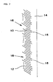
- this carbon fiber 1 has a coaxial stacking morphology of truncated conical tubular graphene layers shown by a computer graphic in FIG. 17.
- Each of the truncated conical tubular graphene layers is formed of a hexagonal carbon layer 10 as shown in FIG. 18.
- the actual hexagonal carbon layers are stacked densely in an axial direction A, they are stacked roughly in FIG. 17 for convenience of description.
- FIG. 19 is a schematic view of FIG. 17.
- Each of the hexagonal carbon layers 10 has a large ring end 20 at one end and a small ring end 22 at the other end in the axial direction.
- the large ring ends 20 are stacked in the axial direction A to form an outer surface 30 of the carbon fiber 1.
- the small ring ends 22 are stacked in the axial direction A to form an inner surface 32 of the carbon fiber 1.
- the carbon fiber 1 is thus in the shape of a hollow core with no bridge and has a center hole 14.
- Benzene as a raw material was fed to a chamber of the reactor using a hydrogen stream at a flow rate of 0.3 l/h and a partial pressure equivalent to the vapor pressure at about 20°C.
- Ferrocene as a catalyst was vaporized at 185°C and fed to the chamber at a concentration of about 3 x 10 -7 mol/s.
- the reaction temperature and the reaction time were about 1100°C and about 20 minutes, respectively.
- a carbon fiber having a herring-bone structure with an average diameter of about 100 nm was obtained.
- a hollow carbon fiber having no bridge at a length ranging from several tens of nanometers to several tens of microns, in which a number of hexagonal carbon layers in the shape of a bottomless cup are stacked, is obtained by adjusting the flow rate of the raw material and the reaction temperature (which are changed depending on the size of the reactor).
- the length of the carbon fiber in which a number of hexagonal carbon layers in the shape of a bottomless cup are stacked may be adjusted by grinding so that one to several hundreds of hexagonal carbon layers in the shape of a bottomless cup are stacked as described later.
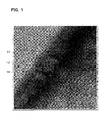
- FIG. 1 is a copy of a transmission electron micrograph showing the carbon fiber having a herring-bone structure manufactured using the vapor growth process.
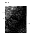
- FIG. 2 is a copy of an enlarged micrograph of FIG. 1, and
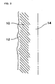
- FIG. 3 is a schematic view of FIG. 2.
- a deposited layer 12 in which an excess amount of amorphous carbon is deposited, is formed to cover the tilted hexagonal carbon layers 10.
- a reference numeral 14 indicates the center hole.
- the center hole 14 has a sufficient space for holding an electrolyte.
- FIG. 20 is a view schematically showing a state in which the deposited films 12 are formed over a wide area of the outer surface 30 of the carbon fiber 1.
- the hexagonal carbon layers 10 are exposed on the large ring ends 20 in the areas in which the outer surface of the carbon fiber 1 is not covered with the deposited films 12. These areas have a high degree of activity.
- the hexagonal carbon layers 10 are exposed on the exposed small ring ends 22.
- the deposited layers 12 are oxidized and pyrolyzed by heating the carbon fiber on which the deposited layers 12 are formed at a temperature of 400°C or more, preferably 500°C or more, and still more preferably 520°C to 530°C for one to several hours in air. As a result, the deposited layers 12 are removed, whereby the edges of the hexagonal carbon layers are further exposed.
- the deposited layers 12 may be removed by washing the carbon fiber with supercritical water, whereby the edges of the hexagonal carbon layers are exposed.
- the deposited layers 12 may be removed by immersing the carbon fiber in hydrochloric acid or sulfuric acid and heating the carbon fiber at about 80°C while stirring using a stirrer.
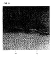
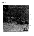
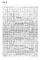
- FIG. 4 is a copy of a transmission electron micrograph of the carbon fiber having a herring-bone structure heated at a temperature of about 530°C for one hour in air.
- FIG. 5 is an enlarged view of FIG. 4
- FIG. 6 is a further enlarged view of FIG. 5
- FIG. 7 is a schematic view of FIG. 6.
- part of the deposited layers 12 is removed by performing a heat treatment or the like, whereby the edges of the hexagonal carbon layers 10 are further exposed.
- the residual deposited layers 12 are considered to be almost pyrolyzed and merely attached to the carbon fiber.
- the deposited layers 12 can be removed completely by combining heat treatment for several hours and washing with supercritical water.
- the carbon fiber 10 in which a number of hexagonal carbon layers in the shape of a bottomless cup are stacked is hollow at a length ranging at least from several tens of nanometers to several tens of microns.
- the tilt angle of the hexagonal carbon layers with respect to the center line is from about 25° to 35°.
- the edges of the hexagonal carbon layers 10 on the outer surface and the inner surface are irregular in the area in which the edges of the hexagonal carbon layers 10 are exposed, whereby minute irregularities 16 at a nanometer (nm) level, specifically, at the level of atoms are formed.
- the irregularities 16 are unclear before removing the deposited layers 12 as shown in FIG. 2. However, the irregularities 16 appear by removing the deposited layers 12 by the heat treatment.
- the exposed edges of the hexagonal carbon layers 10 have an extremely high degree of activity and easily bond to other atoms.
- the reasons therefor are considered to be as follows.
- the heat treatment in air causes the deposited layers 12 to be removed and the number of functional groups containing oxygen such as a phenolic hydroxyl group, carboxyl group, quinone type carbonyl group, and lactone group to be increased on the exposed edges of the hexagonal carbon layers 10.
- These functional groups containing oxygen have high hydrophilicity and high affinity to various types of substances.
- the hollow structure and the irregularities 16 contribute to the anchor effect to a large extent.
- the carbon fibers When forming an anode by securing a large number of carbon fibers using a resin binder, applying the carbon fibers to copper foil, and drying the carbon fibers, the carbon fibers exhibit good adhesion to the binder. This is considered to contribute to an increase in lifetime of the electrode.
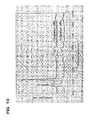
- FIG. 8 shows the Raman spectra of a carbon fiber having a herring-bone structure (sample No. 24PS) after heating at 500°C, 520°C, 530°C, and 540°C for one hour in air.
- FIGS. 5 to 7 show that the deposited layers 12 are removed by the heat treatment.
- the presence of the D peak (1360 cm -1 ) and the G peak (1580 cm -1 ) shows that this sample is a carbon fiber and has no graphitized structure.
- the carbon fiber having a herring-bone structure is considered to have a turbostratic structure in which the carbon layers are disordered.
- This carbon fiber has a turbostratic structure in which the hexagonal carbon layers are stacked in parallel but are shifted in the horizontal direction or rotated. Therefore, the carbon fiber has no crystallographic regularity.
- turbostratic structure The feature of this turbostratic structure is that intercalation of other atoms or the like seldom occurs. However, the turbostratic structure allows intercalation of atoms having a size such as a lithium ion.
- FIG. 9 shows the Raman spectra of carbon fiber samples No. 19PS and No. 24PS in which the edges of the hexagonal carbon layers are exposed by the above heat treatment.
- FIG. 10 shows the Raman spectra of the carbon fiber samples No. 19PS and No. 24PS, heated at 3000°C (common graphitization treatment) after the edges of the hexagonal carbon layers has been exposed.
- the D peak does not disappear even if the carbon fiber in which the edges of the hexagonal carbon layers are exposed is subjected to the graphitization treatment. This means that the carbon fiber is not graphitized by the graphitization treatment.
- a diffraction line did not appear at the 112 plane in X-ray diffractometry (not shown). This also shows that the carbon fiber was not graphitized.
- the carbon fiber is not graphitized by the graphitization treatment because the deposited layers 12, which are easily graphitized, have been removed. This also shows that the remaining portions of the herring-bone structure are not graphitized.
- the resulting carbon fiber in which the edges of the hexagonal carbon layers are exposed is used as an electrode material (additive to an electrode) of a lithium secondary battery.
- the electrode material (carbon fiber) of the present embodiment is hollow with no bridge at a length ranging from several tens of nanometers to several tens of microns, in which a number of hexagonal carbon layers 10 in the shape of a bottomless cup are stacked. Therefore, the electrode material has characteristics by which the electrode material expands and contracts in the longitudinal direction.
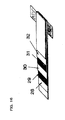
- the carbon fiber expands in the longitudinal direction due to an increase in the gaps between the hexagonal carbon layers 10 (FIG. 11).
- the lithium ions 40 are deintercalated from the gaps between the hexagonal carbon layers 10
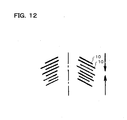
- the carbon fiber contracts in the longitudinal direction due to a decrease in the gaps between the hexagonal carbon layers 10 (FIG. 12).
- the meaning of this is as follows. Stress caused by repeated intercalation and deintercalation of the lithium ions 40 is absorbed by expansion and contraction of the carbon fiber.
- the lithium ions 40 are intercalated or deintercalated from not only the outer surface but also the inner surface of the carbon fiber. Therefore, almost no physical stress is applied to the carbon fiber, whereby the crystal structure is not destroyed. This improves and stabilizes high output characteristics and lifetime performance of the battery.
- the edges of the bottomless cup-shaped hexagonal carbon layers exposed on the inner and outer surfaces of the fiber have an extremely high degree of activity.
- the lithium ions 40 are easily adsorbed on these highly active edges. Therefore, the electrode material can store a large number of lithium ions 40, whereby capacity of the battery can be increased.
- an electrolyte is introduced and held in the center hole 14 of the carbon fiber, a large number of lithium ions 40 can be stored on the edges exposed inside the fiber, and the capacity of the battery can be increased.
- the carbon fiber having the herring-bone structure thus obtained is a short fiber with a length of several tens of microns in which several tens of thousands to several hundreds of thousands of bottomless cup-shaped, specifically, truncated conical tubular hexagonal carbon layers are stacked. This short fiber is insoluble due to a high molecular weight (length).
- the carbon fiber product according to one embodiment of the present invention is obtained by dividing the above short fiber into pieces in which one to several hundreds of hexagonal carbon layers are stacked.
- the carbon fiber product becomes soluble if the molecular weight is reduced by decreasing the number of stacked layers, in particular, if the number of hexagonal carbon layers is one.
- the short fiber may be divided by adding an appropriate amount of water or solvent and grinding the short fiber slowly using a mortar and pestle.
- the short fiber (in which the deposited layers 12 may be formed, or part or all of the deposited layers 12 may be removed) is placed in a mortar, and ground mechanically and slowly using a pestle.
- the carbon fiber in which one to several hundreds of hexagonal carbon layers are stacked can be obtained by experimentally determining the treatment time in a mortar.
- the cyclic hexagonal carbon layers have a comparatively high strength and are bonded to one another by only a weak Van der Waals force, the cyclic hexagonal carbon layers are separated without being crushed between layers in which the bond is particularly weak.
- the short fiber can be separated between the above unit fiber layers while reducing mechanical stress by grinding the short fiber together with ice using a mortar and pestle.
- the carbon fiber may be ground by ball milling on an industrial scale.
- a ball mill manufactured by Kabushikigaisha Asahi Rika Seisakujo was used.
- Balls used were made of alumina with a diameter of 5 mm. 1 g of the above carbon fiber, 200 g of alumina balls, and 50 cc of distilled water were placed in a cell, and treated at a rotational speed of 350 rpm. The carbon fiber was sampled when 1, 3, 5, 10, and 24 hours had elapsed.
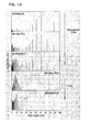
- FIG. 13 shows distributions of the length of the carbon fiber measured using a laser particle size distribution analyzer at each sampling time.
- the fiber length is decreased with the passing of milling time.
- the fiber length is decreased rapidly to 10 ⁇ m or less after 10 hours have elapsed.
- Another peak appears at about 1 ⁇ m after 24 hours have elapsed. This clearly shows that the fiber length was further decreased. The reason why the peak appears at about 1 ⁇ m is considered to be because the length almost equals the diameter, whereby the diameter is counted as the length.
- FIG. 14 is a copy of a transmission electron micrograph of a very interesting carbon fiber of which the length is adjusted in a state in which several tens of bottomless cup-shaped hexagonal carbon layers are stacked.
- the carbon fiber has a hollow shape with no bridge. The edges of the hexagonal carbon layers are exposed on the outer surface side and the inner surface side of the hollow portion.
- the length of the carbon fiber may be adjusted by changing the ball milling conditions or the like.
- the carbon fiber shown in FIG. 14 is in the shape of a tube with a length and a diameter of about 60 nm which has a thin wall and a large hollow portion.
- the carbon fiber is divided as a result of falling from the bottomless cup-shaped hexagonal carbon layer. Therefore, the shape of the hexagonal carbon layers is not changed.
- the carbon fiber becomes a minute particle by adjusting the length, dispersibility in the binder is increased. This increases adhesion to the binder, whereby lifetime of the electrode is increased.
- the carbon fiber having a herring-bone structure is described above.
- the carbon fiber according to the present embodiment is a carbon fiber in which the above carbon fiber is doped with boron atoms (part of carbon atoms of the hexagonal carbon layers are replaced with boron atoms).
- Replacing (doping) with boron atoms is achieved by mixing the carbon fiber with boron oxide (B 2 O 3 ) or boron powder so that the boron content is 5 wt%, for example, and subjecting the mixture to a heat treatment at a temperature of 2500°C or more for about ten minutes in a non-oxidizing atmosphere such as in a graphite resistance furnace or in argon. This treatment enables replacement with 1 to 10 atomic percent of boron atoms.
- the interatomic distance between the boron atom and carbon atom is increased as a result of substitution of the boron atoms for the carbon atoms of the hexagonal carbon layers.
- wide-based conical projections with a boron atom at the top are formed on the smooth hexagonal carbon layers.
- the carbon fiber of the present embodiment in which the hexagonal carbon layers in the shape of a bottomless cup are stacked, has characteristics by which the hexagonal carbon layers are easily separated so that the fiber length can be adjusted.
- the hexagonal carbon layers it is preferable that the hexagonal carbon layers be not separated after the fiber length is adjusted.
- the projections are formed on the hexagonal carbon layers by replacement with the boron atoms, conductive paths for lithium ions are formed between the layers. This enables lithium ions to be easily intercalated or deintercalated between the layers, whereby the capacity can be further increased.
- An anode of the lithium secondary battery is formed by applying the electrode material secured using a binder to electrode foil such as copper foil, and curing the binder.
- An epoxy resin, Teflon (trade name) resin, or the like may be used as the binder.
- the binder content about 5 wt% will suffice.
- graphite may be used as an essential material and the above electrode material may be added thereto as an additive.
- a cathode is formed by applying the electrode material and a lithium-containing oxide, secured using the binder, to electrode foil such as aluminum foil, and curing the binder.
- a lithium-containing oxide oxides such as LiCoO 2 , LiMn 2 O 4 , or LiNiO 2 may be used.
- the carbon fiber is added in an amount of 1 wt% or more.
- electrolyte conventional liquid or gelled electrolyte such as a liquid electrolyte containing propylene carbonate as a solvent and lithium perchlorate as a solute, or a gelled polymer electrolyte produced by adding a small amount of an organic polymer to the liquid electrolyte may be used.
- a lithium secondary battery is formed by attaching leads to the anode and the cathode, winding the anode and the cathode around an insulating separator formed of a porous film interposed therebetween, placing the anode and the cathode in a case, and sealing them by immersing in an electrolyte.
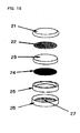
- FIG. 15 is a view showing a button-type lithium secondary battery.
- An upper cover 21, a cathode 22, a glass filter 23, an anode (anode material + PTFE) 24, a packing ring 25, a lower cover 26, and an electrolyte 27 are illustrated.
- FIG. 16 is a view showing a polymer-type lithium secondary battery.
- An electrode film 28, an anode 29, a polymer electrolyte 30, and an electrode film 32 are illustrated.
- the hollow carbon fiber with no bridge at a length ranging from several tens of nanometers to several tens of microns, in which a number of hexagonal carbon layers 10 in the shape of a bottomless cup are stacked is used as the electrode material. Therefore, the carbon fiber is strong enough to withstand stress such as buckling, tension, and twisting due to its flexibility, whereby the carbon fiber excels in reinforcing effect on the electrodes in comparison with a conventional tube-shaped carbon fiber. Moreover, the carbon fiber excels in conductivity as the electrode material.
- the carbon fiber may be used for various types of applications such as an anode material for primary and secondary lithium batteries, and members of fuel cells (polymer electrolyte membrane, catalyst support, separator, and the like).
- an electrode material for a lithium secondary battery excelling in output characteristics, lifetime performance, and stability of performance, enabling an increase in capacity, and excelling in conductivity and electrode reinforcement, and a lithium secondary battery can be provided.
Applications Claiming Priority (2)
| Application Number | Priority Date | Filing Date | Title |
|---|---|---|---|
| JP2001260494 | 2001-08-29 | ||
| JP2001260494A JP3930276B2 (ja) | 2001-08-29 | 2001-08-29 | 気相成長法による炭素繊維、リチウム二次電池用電極材およびリチウム二次電池 |
Publications (3)
| Publication Number | Publication Date |
|---|---|
| EP1288351A2 true EP1288351A2 (de) | 2003-03-05 |
| EP1288351A3 EP1288351A3 (de) | 2003-04-16 |
| EP1288351B1 EP1288351B1 (de) | 2006-10-11 |
Family
ID=19087685
Family Applications (1)
| Application Number | Title | Priority Date | Filing Date |
|---|---|---|---|
| EP02006393A Expired - Fee Related EP1288351B1 (de) | 2001-08-29 | 2002-03-21 | Kohlenstofffaser, Elektrodenmaterial für Lithium-Sekundärbatterie und Lithium-Sekundärbatterie |
Country Status (5)
| Country | Link |
|---|---|
| US (1) | US6881521B2 (de) |
| EP (1) | EP1288351B1 (de) |
| JP (1) | JP3930276B2 (de) |
| CN (1) | CN1266786C (de) |
| DE (1) | DE60215276T2 (de) |
Cited By (2)
| Publication number | Priority date | Publication date | Assignee | Title |
|---|---|---|---|---|
| US6881521B2 (en) * | 2001-08-29 | 2005-04-19 | Gsi Creos Corporation | Carbon fiber, electrode material for lithium secondary battery, and lithium secondary battery |
| TWI410327B (de) * | 2010-01-04 | 2013-10-01 |
Families Citing this family (17)
| Publication number | Priority date | Publication date | Assignee | Title |
|---|---|---|---|---|
| US7150911B2 (en) * | 2001-02-08 | 2006-12-19 | Showa Denko Kabushiki Kaisha | Electrical insulating vapor grown carbon fiber and method for producing the same, and use thereof |
| JP4382311B2 (ja) * | 2001-03-21 | 2009-12-09 | 守信 遠藤 | 気相成長法による炭素繊維の製造方法 |
| JP4014832B2 (ja) * | 2001-03-21 | 2007-11-28 | 守信 遠藤 | フッ素化炭素繊維、これを用いた電池用活物質および固体潤滑材 |
| US6946851B2 (en) * | 2002-07-03 | 2005-09-20 | The Regents Of The University Of California | Carbon nanotube array based sensor |
| TW200508431A (en) * | 2003-08-26 | 2005-03-01 | Showa Denko Kk | Crimped carbon fiber and production method thereof |
| JP2005129446A (ja) * | 2003-10-27 | 2005-05-19 | Hitachi Ltd | 電気化学エネルギー貯蔵デバイス |
| JP2005272184A (ja) * | 2004-03-23 | 2005-10-06 | Honda Motor Co Ltd | 親水性カーボンナノチューブの製造方法 |
| US7465519B2 (en) * | 2004-09-03 | 2008-12-16 | The Hongkong University Of Science And Technology | Lithium-ion battery incorporating carbon nanostructure materials |
| US20060051282A1 (en) * | 2004-09-03 | 2006-03-09 | The Hong Kong University Of Science And Technology | Synthesis of carbon nanostructures |
| JP4696598B2 (ja) * | 2005-03-04 | 2011-06-08 | Jfeエンジニアリング株式会社 | カーボンナノチューブ |
| JP4528324B2 (ja) * | 2007-01-11 | 2010-08-18 | 本田技研工業株式会社 | 熱輸送流体およびその製造方法 |
| JP2008201834A (ja) * | 2007-02-16 | 2008-09-04 | Honda Motor Co Ltd | 熱輸送流体 |
| KR20150091123A (ko) * | 2012-11-29 | 2015-08-07 | 닛본 덴끼 가부시끼가이샤 | 리튬 이온 2차 전지의 부극 활물질의 품질 관리 방법, 리튬 이온 2차 전지의 부극의 제조 방법, 리튬 이온 2차 전지의 제조 방법, 리튬 이온 2차 전지의 부극 및 리튬 이온 2차 전지 |
| JP2016509757A (ja) * | 2013-02-08 | 2016-03-31 | エルジー エレクトロニクス インコーポレイティド | グラフェンリチウムイオンキャパシタ |
| JP6289995B2 (ja) * | 2014-05-13 | 2018-03-07 | 株式会社東芝 | 負極、負極の製造方法、及び非水電解質電池 |
| DE102015200836A1 (de) * | 2015-01-20 | 2016-07-21 | Bayerische Motoren Werke Aktiengesellschaft | Verfahren zur Bestimmung einer Oberflächenstrukturveränderung zumindest einer Carbonfaser |
| JP6941782B2 (ja) * | 2017-03-28 | 2021-09-29 | パナソニックIpマネジメント株式会社 | 負極活物質および電池 |
Citations (5)
| Publication number | Priority date | Publication date | Assignee | Title |
|---|---|---|---|---|
| EP0198558A2 (de) * | 1985-04-15 | 1986-10-22 | The Dow Chemical Company | Verfahren zur Herstellung von Kohlenstoffilamenten und durch dieses Verfahren erhaltene Kohlenstoffilamente |
| WO1995007551A1 (en) * | 1993-09-10 | 1995-03-16 | Hyperion Catalysis International, Inc. | Lithium battery with electrodes containing carbon fibrils |
| EP0762522A1 (de) * | 1995-08-18 | 1997-03-12 | PETOCA, Ltd | Borenthaltender Kohlenstoff für Lithium-Sekundär-Batterie und Verfahren zur Herstellung |
| EP0935302A1 (de) * | 1996-05-07 | 1999-08-11 | Toyo Tanso Co., Ltd. | Kathodenmaterial für lithiumionensekundärbatterie, verfahren zu dessen herstellung und lithiumionensekundärbatterie, in der dieses verwendet wird |
| EP1122344A2 (de) * | 2000-02-04 | 2001-08-08 | Nihon Shinku Gijutsu Kabushiki Kaisha | Graphitnanofaser und deren Verwendung |
Family Cites Families (14)
| Publication number | Priority date | Publication date | Assignee | Title |
|---|---|---|---|---|
| DE68929201T2 (de) * | 1988-01-28 | 2000-11-02 | Hyperion Catalysis Int | Verfahren zur Kohlenstofffibrillenherstellung |
| JPH02259120A (ja) * | 1989-03-29 | 1990-10-19 | Asahi Chem Ind Co Ltd | 表面付着物が存在しない炭素繊維 |
| JP2868317B2 (ja) * | 1990-12-25 | 1999-03-10 | 日機装 株式会社 | 気相成長炭素繊維およびその製造方法 |
| JP2616699B2 (ja) * | 1993-06-03 | 1997-06-04 | 日本電気株式会社 | カーボン・ナノチューブの精製法 |
| US5780101A (en) | 1995-02-17 | 1998-07-14 | Arizona Board Of Regents On Behalf Of The University Of Arizona | Method for producing encapsulated nanoparticles and carbon nanotubes using catalytic disproportionation of carbon monoxide |
| JPH0963585A (ja) * | 1995-08-18 | 1997-03-07 | Petoca:Kk | リチウム系二次電池用炭素材及びその製造法 |
| JP3461805B2 (ja) * | 1999-03-25 | 2003-10-27 | 昭和電工株式会社 | 炭素繊維、その製造方法及び電池用電極 |
| JP4115637B2 (ja) * | 1999-09-01 | 2008-07-09 | 日機装株式会社 | 炭素繊維質物製造装置、炭素繊維質物の製造方法及び炭素繊維質物付着防止装置 |
| JP4382311B2 (ja) * | 2001-03-21 | 2009-12-09 | 守信 遠藤 | 気相成長法による炭素繊維の製造方法 |
| JP2002353075A (ja) * | 2001-03-21 | 2002-12-06 | Morinobu Endo | 電気二重層コンデンサの電極材料およびこれを用いた電気二重層コンデンサ |
| JP4197859B2 (ja) * | 2001-05-30 | 2008-12-17 | 株式会社Gsiクレオス | リチウム二次電池の電極材およびこれを用いたリチウム二次電池 |
| JP2003031221A (ja) * | 2001-07-13 | 2003-01-31 | Univ Shinshu | グラファイト、リチウム二次電池用負極材およびリチウム二次電池 |
| JP3930335B2 (ja) * | 2001-08-29 | 2007-06-13 | 株式会社Gsiクレオス | 気相成長法による炭素繊維、電池用電極材および炭素繊維の製造方法 |
| JP3930276B2 (ja) * | 2001-08-29 | 2007-06-13 | 株式会社Gsiクレオス | 気相成長法による炭素繊維、リチウム二次電池用電極材およびリチウム二次電池 |
-
2001
- 2001-08-29 JP JP2001260494A patent/JP3930276B2/ja not_active Expired - Lifetime
-
2002
- 2002-03-18 US US10/098,375 patent/US6881521B2/en not_active Expired - Lifetime
- 2002-03-21 DE DE60215276T patent/DE60215276T2/de not_active Expired - Lifetime
- 2002-03-21 EP EP02006393A patent/EP1288351B1/de not_active Expired - Fee Related
- 2002-08-29 CN CNB021422885A patent/CN1266786C/zh not_active Expired - Fee Related
Patent Citations (5)
| Publication number | Priority date | Publication date | Assignee | Title |
|---|---|---|---|---|
| EP0198558A2 (de) * | 1985-04-15 | 1986-10-22 | The Dow Chemical Company | Verfahren zur Herstellung von Kohlenstoffilamenten und durch dieses Verfahren erhaltene Kohlenstoffilamente |
| WO1995007551A1 (en) * | 1993-09-10 | 1995-03-16 | Hyperion Catalysis International, Inc. | Lithium battery with electrodes containing carbon fibrils |
| EP0762522A1 (de) * | 1995-08-18 | 1997-03-12 | PETOCA, Ltd | Borenthaltender Kohlenstoff für Lithium-Sekundär-Batterie und Verfahren zur Herstellung |
| EP0935302A1 (de) * | 1996-05-07 | 1999-08-11 | Toyo Tanso Co., Ltd. | Kathodenmaterial für lithiumionensekundärbatterie, verfahren zu dessen herstellung und lithiumionensekundärbatterie, in der dieses verwendet wird |
| EP1122344A2 (de) * | 2000-02-04 | 2001-08-08 | Nihon Shinku Gijutsu Kabushiki Kaisha | Graphitnanofaser und deren Verwendung |
Non-Patent Citations (6)
| Title |
|---|
| ENDO M ET AL: "Pyrolytic carbon nanotubes from vapor-grown carbon fibers" CARBON, ELSEVIER SCIENCE PUBLISHING, NEW YORK, NY, US, vol. 33, no. 7, 1995, pages 873-881, XP004022501 ISSN: 0008-6223 * |
| ENDO M ET AL: "RECENT DEVELOPMENT OF CARBON MATERIALS FOR LI ION BATTERIES" CARBON, ELSEVIER SCIENCE PUBLISHING, NEW YORK, NY, US, vol. 38, no. 2, 2000, pages 183-197, XP000911750 ISSN: 0008-6223 * |
| ENDO M ET AL: "Structural characterization of cup-stacked nanofibers with an entirely hollow core" APPLIED PHYSICS LETTERS, vol. 80, no. 7, 18 February 2002 (2002-02-18), pages 1267-1269, XP002230243 * |
| ENDO M ET AL: "Vapor-grown carbon fibers (VGCFs) - Basic properties and their battery applications" CARBON, XX, XX, vol. 39, no. 9, August 2001 (2001-08), pages 1287-1297, XP004319972 ISSN: 0008-6223 * |
| FLANDROIS S ET AL: "Carbon materials for lithium-ion rechargeable batteries" CARBON, XX, XX, vol. 37, no. 2, February 1999 (1999-02), pages 165-180, XP004158110 ISSN: 0008-6223 * |
| TERRONES H ET AL: "Graphitic cones in palladium catalysed carbon nanofibres" CHEMICAL PHYSICS LETTERS, vol. 343, 3 August 2001 (2001-08-03), pages 241-250, XP002230244 * |
Cited By (2)
| Publication number | Priority date | Publication date | Assignee | Title |
|---|---|---|---|---|
| US6881521B2 (en) * | 2001-08-29 | 2005-04-19 | Gsi Creos Corporation | Carbon fiber, electrode material for lithium secondary battery, and lithium secondary battery |
| TWI410327B (de) * | 2010-01-04 | 2013-10-01 |
Also Published As
| Publication number | Publication date |
|---|---|
| CN1419305A (zh) | 2003-05-21 |
| US20030044685A1 (en) | 2003-03-06 |
| DE60215276T2 (de) | 2007-08-30 |
| DE60215276D1 (de) | 2006-11-23 |
| CN1266786C (zh) | 2006-07-26 |
| JP3930276B2 (ja) | 2007-06-13 |
| JP2003073929A (ja) | 2003-03-12 |
| EP1288351A3 (de) | 2003-04-16 |
| US6881521B2 (en) | 2005-04-19 |
| EP1288351B1 (de) | 2006-10-11 |
Similar Documents
| Publication | Publication Date | Title |
|---|---|---|
| EP1262579A2 (de) | Elektrodenmaterial für Lithium-Sekundärbatterie und Lithium-Sekundärbatterie die das Material verwendet | |
| US6881521B2 (en) | Carbon fiber, electrode material for lithium secondary battery, and lithium secondary battery | |
| US11394028B2 (en) | Graphene-carbon hybrid foam-protected anode active material coating for lithium-ion batteries | |
| KR101484432B1 (ko) | 리튬 이온 2차 전지용 부극 재료, 리튬 이온 2차 전지 부극 및 리튬 이온 2차 전지 | |
| KR101131937B1 (ko) | 리튬 이차 전지용 음극 활물질, 이의 제조방법 및 이를 포함하는 리튬 이차 전지 | |
| KR100981909B1 (ko) | 리튬 이차 전지용 음극 활물질, 그의 제조 방법 및 그를포함하는 리튬 이차 전지 | |
| US9077044B2 (en) | Anode material | |
| KR100751772B1 (ko) | 배터리 전극용 탄소재료와 그 제조방법 및 용도 | |
| KR101708360B1 (ko) | 음극 활물질 및 이를 채용한 리튬 전지 | |
| EP1246211B1 (de) | Elektrodenmaterial für elektrischen Doppelschichtkondensator und elektrischer Doppelschichtkondensator unter Verwendung desselben | |
| JP3258246B2 (ja) | 電気化学的電池用緻密化炭素 | |
| EP0742295B1 (de) | Kohlenstofffaser für Sekundärbatterie-Elektrode und Verfahren zu ihrer Herstellung | |
| JPWO2002093666A1 (ja) | 非水電解質二次電池及びその正極材料の製造方法 | |
| Kumar et al. | Carbonaceous anode materials for lithium-ion batteries-the road ahead | |
| KR101986680B1 (ko) | 리튬 이차전지용 음극 활물질, 그 제조방법 및 리튬 이차전지용 음극 활물질을 포함하는 리튬 이차전지 | |
| US20210135219A1 (en) | Graphene-Encapsulated Graphene-Supported Phosphorus-Based Anode Active Material for Lithium-Ion or Sodium-ion Batteries | |
| US20210367229A1 (en) | Conducting polymer network/expanded graphite-enabled negative electrode for a lithium-ion battery | |
| US11515529B2 (en) | Core-shell electrochemically active particles with modified microstructure and use for secondary battery electrodes | |
| JP2019175851A (ja) | リチウムイオン二次電池用負極活物質及びその製造方法 | |
| KR101004443B1 (ko) | 리튬 이차 전지용 음극 활물질, 이의 제조방법 및 이를 포함하는 리튬 이차 전지 | |
| WO2020154258A1 (en) | Graphene-carbon hybrid foam-protected anode active material coating for lithium-ion batteries | |
| JPH0992284A (ja) | 二次電池電極用黒鉛質材料及びその製造方法並びに二次電池 | |
| US20240025746A1 (en) | Carbon-silicon composite and preparation method therefor | |
| KR101855848B1 (ko) | 팽창흑연 및 실리콘 융합체를 포함하는 리튬 이차전지용 음극활물질, 그 제조방법 및 리튬 이차전지용 음극활물질을 포함하는 리튬 이차전지 | |
| US20210359292A1 (en) | Conducting polymer network/graphene-protected negative electrode for a lithium-ion battery |
Legal Events
| Date | Code | Title | Description |
|---|---|---|---|
| PUAI | Public reference made under article 153(3) epc to a published international application that has entered the european phase |
Free format text: ORIGINAL CODE: 0009012 |
|
| PUAL | Search report despatched |
Free format text: ORIGINAL CODE: 0009013 |
|
| AK | Designated contracting states |
Kind code of ref document: A2 Designated state(s): AT BE CH CY DE DK ES FI FR GB GR IE IT LI LU MC NL PT SE TR |
|
| AX | Request for extension of the european patent |
Extension state: AL LT LV MK RO SI |
|
| RIC1 | Information provided on ipc code assigned before grant |
Ipc: 7D 01F 11/12 B Ipc: 7D 01F 9/127 A Ipc: 7H 01M 4/58 B |
|
| AK | Designated contracting states |
Designated state(s): AT BE CH CY DE DK ES FI FR GB GR IE IT LI LU MC NL PT SE TR |
|
| AX | Request for extension of the european patent |
Extension state: AL LT LV MK RO SI |
|
| 17P | Request for examination filed |
Effective date: 20031001 |
|
| AKX | Designation fees paid |
Designated state(s): DE FR GB IT |
|
| GRAP | Despatch of communication of intention to grant a patent |
Free format text: ORIGINAL CODE: EPIDOSNIGR1 |
|
| GRAS | Grant fee paid |
Free format text: ORIGINAL CODE: EPIDOSNIGR3 |
|
| GRAA | (expected) grant |
Free format text: ORIGINAL CODE: 0009210 |
|
| AK | Designated contracting states |
Kind code of ref document: B1 Designated state(s): DE FR GB IT |
|
| REG | Reference to a national code |
Ref country code: GB Ref legal event code: FG4D |
|
| REF | Corresponds to: |
Ref document number: 60215276 Country of ref document: DE Date of ref document: 20061123 Kind code of ref document: P |
|
| ET | Fr: translation filed | ||
| PLBE | No opposition filed within time limit |
Free format text: ORIGINAL CODE: 0009261 |
|
| STAA | Information on the status of an ep patent application or granted ep patent |
Free format text: STATUS: NO OPPOSITION FILED WITHIN TIME LIMIT |
|
| 26N | No opposition filed |
Effective date: 20070712 |
|
| PGFP | Annual fee paid to national office [announced via postgrant information from national office to epo] |
Ref country code: GB Payment date: 20090319 Year of fee payment: 8 |
|
| PGFP | Annual fee paid to national office [announced via postgrant information from national office to epo] |
Ref country code: IT Payment date: 20090320 Year of fee payment: 8 |
|
| PGFP | Annual fee paid to national office [announced via postgrant information from national office to epo] |
Ref country code: FR Payment date: 20090323 Year of fee payment: 8 |
|
| GBPC | Gb: european patent ceased through non-payment of renewal fee |
Effective date: 20100321 |
|
| REG | Reference to a national code |
Ref country code: FR Ref legal event code: ST Effective date: 20101130 |
|
| PG25 | Lapsed in a contracting state [announced via postgrant information from national office to epo] |
Ref country code: FR Free format text: LAPSE BECAUSE OF NON-PAYMENT OF DUE FEES Effective date: 20100331 |
|
| PG25 | Lapsed in a contracting state [announced via postgrant information from national office to epo] |
Ref country code: IT Free format text: LAPSE BECAUSE OF NON-PAYMENT OF DUE FEES Effective date: 20100321 Ref country code: GB Free format text: LAPSE BECAUSE OF NON-PAYMENT OF DUE FEES Effective date: 20100321 |
|
| REG | Reference to a national code |
Ref country code: DE Ref legal event code: R082 Ref document number: 60215276 Country of ref document: DE Representative=s name: WUNDERLICH & HEIM PATENTANWAELTE PARTNERSCHAFT, DE |
|
| PGFP | Annual fee paid to national office [announced via postgrant information from national office to epo] |
Ref country code: DE Payment date: 20190327 Year of fee payment: 18 |
|
| REG | Reference to a national code |
Ref country code: DE Ref legal event code: R119 Ref document number: 60215276 Country of ref document: DE |
|
| PG25 | Lapsed in a contracting state [announced via postgrant information from national office to epo] |
Ref country code: DE Free format text: LAPSE BECAUSE OF NON-PAYMENT OF DUE FEES Effective date: 20201001 |