EP1281008B1 - Synchronisiereinrichtung mit asymmetrischer verzahnung - Google Patents
Synchronisiereinrichtung mit asymmetrischer verzahnung Download PDFInfo
- Publication number
- EP1281008B1 EP1281008B1 EP01938179A EP01938179A EP1281008B1 EP 1281008 B1 EP1281008 B1 EP 1281008B1 EP 01938179 A EP01938179 A EP 01938179A EP 01938179 A EP01938179 A EP 01938179A EP 1281008 B1 EP1281008 B1 EP 1281008B1
- Authority
- EP
- European Patent Office
- Prior art keywords
- sliding sleeve
- gear
- teeth
- locking surface
- clutch body
- Prior art date
- Legal status (The legal status is an assumption and is not a legal conclusion. Google has not performed a legal analysis and makes no representation as to the accuracy of the status listed.)
- Expired - Lifetime
Links
Images
Classifications
-
- F—MECHANICAL ENGINEERING; LIGHTING; HEATING; WEAPONS; BLASTING
- F16—ENGINEERING ELEMENTS AND UNITS; GENERAL MEASURES FOR PRODUCING AND MAINTAINING EFFECTIVE FUNCTIONING OF MACHINES OR INSTALLATIONS; THERMAL INSULATION IN GENERAL
- F16D—COUPLINGS FOR TRANSMITTING ROTATION; CLUTCHES; BRAKES
- F16D23/00—Details of mechanically-actuated clutches not specific for one distinct type
- F16D23/02—Arrangements for synchronisation, also for power-operated clutches
- F16D23/04—Arrangements for synchronisation, also for power-operated clutches with an additional friction clutch
- F16D23/06—Arrangements for synchronisation, also for power-operated clutches with an additional friction clutch and a blocking mechanism preventing the engagement of the main clutch prior to synchronisation
- F16D2023/0656—Details of the tooth structure; Arrangements of teeth
-
- Y—GENERAL TAGGING OF NEW TECHNOLOGICAL DEVELOPMENTS; GENERAL TAGGING OF CROSS-SECTIONAL TECHNOLOGIES SPANNING OVER SEVERAL SECTIONS OF THE IPC; TECHNICAL SUBJECTS COVERED BY FORMER USPC CROSS-REFERENCE ART COLLECTIONS [XRACs] AND DIGESTS
- Y10—TECHNICAL SUBJECTS COVERED BY FORMER USPC
- Y10T—TECHNICAL SUBJECTS COVERED BY FORMER US CLASSIFICATION
- Y10T74/00—Machine element or mechanism
- Y10T74/19—Gearing
- Y10T74/19219—Interchangeably locked
- Y10T74/19284—Meshing assisters
Definitions
- the invention relates to a manual transmission according to the preamble of claim 1.
- a manual transmission with asymmetric toothing FR-A-1,152,699 is known.
- Synchronizing devices for manual transmissions of motor vehicles have a by axial displacement with a shaft nadostarr connectable and provided with an internal sliding sleeve on, provided with an external gear coupling body and a synchronizer ring in the circumferential direction with the sliding sleeve via an external toothing in positive and with the coupling body in frictional Connection stands.
- the toothing of the synchronizer ring has locking surfaces arranged at an angle to one another for engagement in corresponding blocking surfaces of the toothing of the sliding sleeve.
- Such synchronizers are widely known and z. As described in DE-PS 26 59 448. If a gear is engaged by moving the sliding sleeve in the axial direction of the neutral position, so it takes the synchronizer ring and presses him against a counter-cone of the coupling body. A frictional connection between the synchronizer ring and coupling body is thereby produced, whereby a speed equalization between the shaft, the sliding sleeve and the synchronizer ring and the coupling body and the associated gear of the wheel pair to be switched is achieved.
- Locking surfaces provided on the synchronizer ring are thereby brought into a position in which they engage with associated and adapted blocking surfaces on the sliding sleeve and thereby an axial displacement of the sliding sleeve in the direction of the Prevent coupling body.
- the locking surfaces are usually mounted on an external toothing of the synchronizer ring, which is adapted to the external toothing of the coupling body; the mating surfaces are attached to the ends of the teeth, which form the internal toothing of the sliding sleeve. Only when reaching the synchronous speed, the sliding sleeve can be inserted past the locking surfaces of the synchronizer ring in the outer toothing of the coupling body.
- the front in the direction of locking surfaces on the sliding sleeve have a greater axial extent than the rear locking surfaces in the direction.
- the external teeth of the coupling body and the locking surfaces of the sliding sleeve are designed asymmetrically, but such that they have the same inclination relative to the axial direction, but with respect to the longitudinal center of each tooth are offset such that the two belonging to a tooth treads different have axial expansions and thus different sized surfaces, wherein the front in the direction of locking surfaces on the sliding sleeve have the greater axial extent, compared with the rear locking surface in the direction.
- the effect is selectively enhanced that at an upshifting after the end of the synchronizing process, the synchronizer ring enters the reverse switching position before the sliding sleeve has passed with its remindschaltsperrkante in the axial direction of the remindschaltsperrkante of the synchronizer ring.
- the reverse disengagement position is the position on the opposite rotation stop, while the remindschaltsperr materials is the long of the two locking surfaces on the sliding sleeve. After unlocking from this reverse lock position can then be terminated without Einspurkratzen the switching process. Due to the asymmetry described above but occurs in the unlocking after an upshift when entering the synchronizer ring in the reverse lock position, a force pulse on the sliding sleeve, which is clearly felt as a shock on the shift lever.
- the invention has for its object to avoid the force pulse on the sliding sleeve and thus to prevent the impact acting on the shift lever.
- This situation applies both to the assembly of the synchronizer on the main shaft and transmission output shaft, then it is the front in the running direction locking surface, the sliding sleeve, the synchronizer ring and the synchronizer body speed constant are and the speed of the loose gear is synchronized, as well as for the assembly of the synchronizer on the countershaft, in which the speed of the loose gear is constant and synchronizes the speed of the sliding sleeve, synchronizer ring and synchronizer body is, then it is the rear in the direction of locking surface.
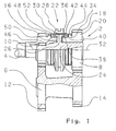
- Fig. 1 shows a part of a transmission 2 with an input shaft 4 and a countershaft 6.
- a main shaft 8 is rotatably mounted in a bearing 10.
- the countershaft 6 has two fixed gears 12 and 14.
- a toothing 16 is fixed.
- a further toothing 18 is provided on a loose gear 20 that is rotatably mounted on the main shaft 8.
- the toothing 12 meshes with the toothing 16, while the toothing 14 meshes with the toothing 18.
- a synchronizer 22 has a synchronizer body 24 which is fixedly formed on the main shaft 8.
- a synchronizer ring 34 is provided with its frustoconical outer friction surface 36 on a correspondingly shaped, also frusto-conical, inner friction surface 38 of the coupling body 40.
- the locking teeth 42 on the synchronizer ring 34 and the coupling teeth 44 on the coupling body 40 are formed so that the sliding sleeve 28 can engage with its internal teeth 26 in these teeth 42 and 44 when the sliding sleeve 28 is axially displaced.
- the input shaft 4 also has a coupling body 46 with coupling teeth 48 and a synchronizer ring 50 with locking teeth 52.
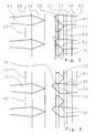
- FIG. 2 shows the internal toothing 26 of the sliding sleeve 28, which has an asymmetrically formed tip.
- the side 54 of the toothing 26 forms a greater axial extent 60 than the axial extent 58 on the side 56.
- the arrow 64 indicates the direction of rotation of the sliding sleeve 28, the arrow 66, the direction of rotation of the coupling body 46 and the arrow 68, the direction of action of a loss torque by the deceleration of the coupling body 46.
- the speed of the coupling body 46 is adjusted during synchronization to the speed of the sliding sleeve 28, while the synchronizer body 24, the synchronizer ring 50 and the sliding sleeve 28 remain constant in their speed.
- Fig. 3 the unlock state is shown.
- the unlocking phase of the synchronizer ring 50 has taken the same speed as the coupling body 46 through the frictional connection on the frusto-conical friction surfaces.
- the synchronizer ring 50 is thereby rotated with the coupling body 46 in the direction of the acting loss torque 68.
- the outer edge 70 is the remindschaltsperrseite 72 on the sliding sleeve 28 in a direction of the tip of the toothing 26 preferred position.
- the outer edge 70 no longer accumulates on the blocking side 74 of the ratchet teeth 52.
- the sliding sleeve 28 slides with the remindschaltsperrseite 72 on the side edge 76 of the ratchet 52 over. An impulse by the impact of the side 56 on the locking side 74 and a rejection of the sliding sleeve 28 in the axial direction is avoided.
Landscapes
- Engineering & Computer Science (AREA)
- General Engineering & Computer Science (AREA)
- Mechanical Engineering (AREA)
- Mechanical Operated Clutches (AREA)
Applications Claiming Priority (3)
| Application Number | Priority Date | Filing Date | Title |
|---|---|---|---|
| DE10022509A DE10022509A1 (de) | 2000-05-10 | 2000-05-10 | Synchronisiereinrichtung mit asymmetrischer Verzahnung |
| DE10022509 | 2000-05-10 | ||
| PCT/EP2001/005115 WO2001086163A1 (de) | 2000-05-10 | 2001-05-05 | Synchronisiereinrichtung mit asymmetrischer verzahnung |
Publications (2)
| Publication Number | Publication Date |
|---|---|
| EP1281008A1 EP1281008A1 (de) | 2003-02-05 |
| EP1281008B1 true EP1281008B1 (de) | 2006-10-11 |
Family
ID=7641273
Family Applications (1)
| Application Number | Title | Priority Date | Filing Date |
|---|---|---|---|
| EP01938179A Expired - Lifetime EP1281008B1 (de) | 2000-05-10 | 2001-05-05 | Synchronisiereinrichtung mit asymmetrischer verzahnung |
Country Status (6)
| Country | Link |
|---|---|
| US (1) | US6729458B2 (OSRAM) |
| EP (1) | EP1281008B1 (OSRAM) |
| JP (1) | JP5093954B2 (OSRAM) |
| DE (2) | DE10022509A1 (OSRAM) |
| ES (1) | ES2273843T3 (OSRAM) |
| WO (1) | WO2001086163A1 (OSRAM) |
Families Citing this family (8)
| Publication number | Priority date | Publication date | Assignee | Title |
|---|---|---|---|---|
| JP2007211966A (ja) * | 2006-02-13 | 2007-08-23 | Aichi Mach Ind Co Ltd | 同期装置 |
| DE102007058800A1 (de) | 2007-12-06 | 2009-06-10 | GM Global Technology Operations, Inc., Detroit | Sperrsynchronisiereinrichtung |
| DE102009054942A1 (de) * | 2009-12-18 | 2011-06-22 | ZF Friedrichshafen AG, 88046 | Schalteinrichtung für ein Zahnräderwechselgetriebe |
| JP5384376B2 (ja) * | 2010-01-14 | 2014-01-08 | アイシン・エーアイ株式会社 | デュアルクラッチ式自動変速機 |
| DE102011077748A1 (de) * | 2011-06-17 | 2012-12-20 | Zf Friedrichshafen Ag | Verbindungsvorrichtung für außerhalb eines Zahnräderwechselgetriebes |
| FR3004229B1 (fr) * | 2013-04-05 | 2016-08-19 | Renault Sa | Procede de controle du crabotage a l'arret d'une boite de vitesses |
| DE102014107371A1 (de) * | 2014-05-26 | 2015-11-26 | Hoerbiger Antriebstechnik Holding Gmbh | Synchronisiervorrichtung und Synchronisationsverfahren |
| DE102017119612A1 (de) * | 2016-09-02 | 2018-03-08 | Schaeffler Technologies AG & Co. KG | Synchronisiereinrichtung |
Family Cites Families (12)
| Publication number | Priority date | Publication date | Assignee | Title |
|---|---|---|---|---|
| FR1152699A (fr) | 1955-05-02 | 1958-02-21 | Daimler Benz Ag | Dispositif de synchronisation pour les accouplements à griffes des changements de vitesse, en particulier pour voitures automobiles |
| DE966366C (de) * | 1955-05-03 | 1957-08-01 | Daimler Benz Ag | Synchronisiervorrichtung fuer die Klauenkupplungen von Wechselgetrieben, insbesondere fuer Kraftfahrzeuge |
| JPS50122732U (OSRAM) * | 1974-03-27 | 1975-10-07 | ||
| DE2659448C2 (de) | 1976-12-30 | 1981-11-26 | Getrag Getriebe- Und Zahnradfabrik Gmbh, 7140 Ludwigsburg | Synchronisiereinrichtung für Schaltkupplungen, insbes. von Schaltgetrieben |
| DE3444670C1 (de) | 1984-12-07 | 1986-07-17 | Getrag Getriebe- Und Zahnradfabrik Gmbh, 7140 Ludwigsburg | Synchronisiereinrichtung fuer Schaltkupplungen |
| DE3728903C1 (de) | 1987-08-29 | 1988-11-24 | Daimler Benz Ag | Kupplungsverzahnung einer sperrsynchronisierten Schaltkupplung insbesondere eines Gangwechselgetriebes mit von ihrer Welle abschaltbaren Zahnraedern |
| US4989706A (en) * | 1989-10-25 | 1991-02-05 | Eaton Corporation | Synchronizer |
| JP3272131B2 (ja) * | 1993-12-27 | 2002-04-08 | マツダ株式会社 | 歯車変速機の噛合装置 |
| JPH07190092A (ja) * | 1993-12-27 | 1995-07-28 | Mazda Motor Corp | 歯車変速機の噛合装置 |
| JPH09273571A (ja) | 1996-04-01 | 1997-10-21 | Mazda Motor Corp | 変速機の同期装置 |
| DE19646850C1 (de) * | 1996-11-13 | 1997-11-20 | Daimler Benz Ag | Synchronisiereinrichtung eines Zahnräderwechselgetriebes |
| JPH11351272A (ja) | 1998-06-09 | 1999-12-24 | Fuji Heavy Ind Ltd | 自動車用手動変速機の同期装置 |
-
2000
- 2000-05-10 DE DE10022509A patent/DE10022509A1/de not_active Withdrawn
-
2001
- 2001-05-05 JP JP2001582735A patent/JP5093954B2/ja not_active Expired - Fee Related
- 2001-05-05 DE DE50111203T patent/DE50111203D1/de not_active Expired - Lifetime
- 2001-05-05 ES ES01938179T patent/ES2273843T3/es not_active Expired - Lifetime
- 2001-05-05 US US10/258,871 patent/US6729458B2/en not_active Expired - Fee Related
- 2001-05-05 WO PCT/EP2001/005115 patent/WO2001086163A1/de not_active Ceased
- 2001-05-05 EP EP01938179A patent/EP1281008B1/de not_active Expired - Lifetime
Also Published As
| Publication number | Publication date |
|---|---|
| WO2001086163A1 (de) | 2001-11-15 |
| JP2003536027A (ja) | 2003-12-02 |
| US6729458B2 (en) | 2004-05-04 |
| DE10022509A1 (de) | 2001-11-15 |
| JP5093954B2 (ja) | 2012-12-12 |
| DE50111203D1 (de) | 2006-11-23 |
| US20030106762A1 (en) | 2003-06-12 |
| EP1281008A1 (de) | 2003-02-05 |
| ES2273843T3 (es) | 2007-05-16 |
Similar Documents
| Publication | Publication Date | Title |
|---|---|---|
| DE3622464C1 (OSRAM) | ||
| DE102007010307B3 (de) | Schaltkupplungsanordnung | |
| DE3728903C1 (de) | Kupplungsverzahnung einer sperrsynchronisierten Schaltkupplung insbesondere eines Gangwechselgetriebes mit von ihrer Welle abschaltbaren Zahnraedern | |
| DE69203137T2 (de) | Schiebbare Kupplungsmuffe für Synchronisiereinrichtung. | |
| DE3411351C1 (de) | Synchronisiereinrichtungen fuer Schaltkupplungen | |
| EP3472484A1 (de) | Synchronisationsvorrichtung für ein schaltgetriebe | |
| EP2452098B1 (de) | Doppelkupplungsgetriebe und verfahren zur steuerung eines doppelkupplungsgetriebes | |
| DE102009051707A1 (de) | Mehrfachsynchronisationsbaugruppe eines Schaltgetriebes und Schaltgetriebe | |
| EP1281008B1 (de) | Synchronisiereinrichtung mit asymmetrischer verzahnung | |
| EP1002199B1 (de) | Kupplungszahn einer schaltmuffe einer zahnradkupplung zum ankuppeln eines zahnrades an seine welle | |
| DE4224271A1 (de) | Synchronisiereinrichtung für Stufengetriebe von Kraftfahrzeugen | |
| EP1101965B1 (de) | Mehrfach-Synchronisiereinheit für Schaltgetriebe | |
| DE10103423A1 (de) | Synchronisiereinrichtung mit asymmetrischer Verzahnung | |
| WO2011023315A1 (de) | Synchronring eines schaltgetriebes | |
| DE19626194A1 (de) | Synchronisiereinrichtung für Schaltgetriebe | |
| DE102014019011A1 (de) | Stufengetriebe für einen Kraftwagen, insbesondere einen Nutzkraftwagen | |
| DE2324860C3 (de) | Keilring bei einem Synchronschaltgetriebe, insbesondere für Kraftfahrzeuge | |
| DE4203540A1 (de) | Synchronisiereinrichtung fuer schaltkupplungen | |
| DE19701538B4 (de) | Getriebeschaltung mit Sperrsynchronisierung | |
| DE202010004770U1 (de) | Synchronisationseinheit eines Schaltgetriebes | |
| DE4224268A1 (de) | Synchronisiereinrichtung für Stufengetriebe von Kraftfahrzeugen | |
| DE102011075504A1 (de) | Arretierung | |
| DE10161596A1 (de) | Synchronisierung | |
| DE10335477A1 (de) | Ganghaltesystem | |
| DE4224270A1 (de) | Synchronisiereinrichtung für Stufengetriebe von Kraftfahrzeugen |
Legal Events
| Date | Code | Title | Description |
|---|---|---|---|
| PUAI | Public reference made under article 153(3) epc to a published international application that has entered the european phase |
Free format text: ORIGINAL CODE: 0009012 |
|
| 17P | Request for examination filed |
Effective date: 20020828 |
|
| AK | Designated contracting states |
Designated state(s): AT BE CH CY DE DK ES FI FR GB GR IE IT LI LU MC NL PT SE TR |
|
| AX | Request for extension of the european patent |
Extension state: AL LT LV MK RO SI |
|
| RBV | Designated contracting states (corrected) |
Designated state(s): AT BE CH CY DE ES FR GB LI |
|
| 17Q | First examination report despatched |
Effective date: 20050128 |
|
| GRAP | Despatch of communication of intention to grant a patent |
Free format text: ORIGINAL CODE: EPIDOSNIGR1 |
|
| GRAS | Grant fee paid |
Free format text: ORIGINAL CODE: EPIDOSNIGR3 |
|
| GRAA | (expected) grant |
Free format text: ORIGINAL CODE: 0009210 |
|
| AK | Designated contracting states |
Kind code of ref document: B1 Designated state(s): DE ES FR GB |
|
| RBV | Designated contracting states (corrected) |
Designated state(s): DE ES FR GB |
|
| REG | Reference to a national code |
Ref country code: GB Ref legal event code: FG4D Free format text: NOT ENGLISH |
|
| REF | Corresponds to: |
Ref document number: 50111203 Country of ref document: DE Date of ref document: 20061123 Kind code of ref document: P |
|
| GBT | Gb: translation of ep patent filed (gb section 77(6)(a)/1977) |
Effective date: 20061213 |
|
| ET | Fr: translation filed | ||
| REG | Reference to a national code |
Ref country code: ES Ref legal event code: FG2A Ref document number: 2273843 Country of ref document: ES Kind code of ref document: T3 |
|
| PLBE | No opposition filed within time limit |
Free format text: ORIGINAL CODE: 0009261 |
|
| STAA | Information on the status of an ep patent application or granted ep patent |
Free format text: STATUS: NO OPPOSITION FILED WITHIN TIME LIMIT |
|
| 26N | No opposition filed |
Effective date: 20070712 |
|
| PGFP | Annual fee paid to national office [announced via postgrant information from national office to epo] |
Ref country code: GB Payment date: 20120502 Year of fee payment: 12 Ref country code: FR Payment date: 20120608 Year of fee payment: 12 |
|
| PGFP | Annual fee paid to national office [announced via postgrant information from national office to epo] |
Ref country code: ES Payment date: 20120607 Year of fee payment: 12 |
|
| GBPC | Gb: european patent ceased through non-payment of renewal fee |
Effective date: 20130505 |
|
| REG | Reference to a national code |
Ref country code: FR Ref legal event code: ST Effective date: 20140131 |
|
| PG25 | Lapsed in a contracting state [announced via postgrant information from national office to epo] |
Ref country code: GB Free format text: LAPSE BECAUSE OF NON-PAYMENT OF DUE FEES Effective date: 20130505 |
|
| PG25 | Lapsed in a contracting state [announced via postgrant information from national office to epo] |
Ref country code: FR Free format text: LAPSE BECAUSE OF NON-PAYMENT OF DUE FEES Effective date: 20130531 |
|
| REG | Reference to a national code |
Ref country code: ES Ref legal event code: FD2A Effective date: 20140912 |
|
| PG25 | Lapsed in a contracting state [announced via postgrant information from national office to epo] |
Ref country code: ES Free format text: LAPSE BECAUSE OF NON-PAYMENT OF DUE FEES Effective date: 20130506 |
|
| PGFP | Annual fee paid to national office [announced via postgrant information from national office to epo] |
Ref country code: DE Payment date: 20200422 Year of fee payment: 20 |
|
| REG | Reference to a national code |
Ref country code: DE Ref legal event code: R071 Ref document number: 50111203 Country of ref document: DE |