EP1279986A1 - Dispositif pour la micro - manipulation de specimens biologiques - Google Patents
Dispositif pour la micro - manipulation de specimens biologiques Download PDFInfo
- Publication number
- EP1279986A1 EP1279986A1 EP02102053A EP02102053A EP1279986A1 EP 1279986 A1 EP1279986 A1 EP 1279986A1 EP 02102053 A EP02102053 A EP 02102053A EP 02102053 A EP02102053 A EP 02102053A EP 1279986 A1 EP1279986 A1 EP 1279986A1
- Authority
- EP
- European Patent Office
- Prior art keywords
- microscope
- control
- motor
- control panel
- micromanipulator
- Prior art date
- Legal status (The legal status is an assumption and is not a legal conclusion. Google has not performed a legal analysis and makes no representation as to the accuracy of the status listed.)
- Ceased
Links
- 230000006870 function Effects 0.000 claims abstract description 27
- 230000015654 memory Effects 0.000 claims description 13
- 230000008878 coupling Effects 0.000 claims description 4
- 238000010168 coupling process Methods 0.000 claims description 4
- 238000005859 coupling reaction Methods 0.000 claims description 4
- 238000003698 laser cutting Methods 0.000 claims description 3
- 238000005286 illumination Methods 0.000 description 10
- 210000004027 cell Anatomy 0.000 description 9
- 238000003384 imaging method Methods 0.000 description 9
- 210000003850 cellular structure Anatomy 0.000 description 5
- 238000002474 experimental method Methods 0.000 description 5
- 238000002347 injection Methods 0.000 description 5
- 239000007924 injection Substances 0.000 description 5
- 238000000034 method Methods 0.000 description 4
- 238000001000 micrograph Methods 0.000 description 4
- 230000001276 controlling effect Effects 0.000 description 3
- 238000011161 development Methods 0.000 description 3
- 238000009826 distribution Methods 0.000 description 3
- 210000004247 hand Anatomy 0.000 description 3
- 239000007788 liquid Substances 0.000 description 3
- 230000006855 networking Effects 0.000 description 3
- 238000004113 cell culture Methods 0.000 description 2
- 210000003855 cell nucleus Anatomy 0.000 description 2
- 238000005520 cutting process Methods 0.000 description 2
- 238000002795 fluorescence method Methods 0.000 description 2
- 238000010438 heat treatment Methods 0.000 description 2
- 238000009434 installation Methods 0.000 description 2
- 238000001001 laser micro-dissection Methods 0.000 description 2
- 239000000463 material Substances 0.000 description 2
- 238000012544 monitoring process Methods 0.000 description 2
- 238000003825 pressing Methods 0.000 description 2
- 238000001228 spectrum Methods 0.000 description 2
- 230000002238 attenuated effect Effects 0.000 description 1
- 230000008901 benefit Effects 0.000 description 1
- 230000005540 biological transmission Effects 0.000 description 1
- 210000000170 cell membrane Anatomy 0.000 description 1
- 230000008859 change Effects 0.000 description 1
- 238000013016 damping Methods 0.000 description 1
- 230000003247 decreasing effect Effects 0.000 description 1
- 238000013461 design Methods 0.000 description 1
- 210000002257 embryonic structure Anatomy 0.000 description 1
- 238000005562 fading Methods 0.000 description 1
- 238000003702 image correction Methods 0.000 description 1
- 238000003780 insertion Methods 0.000 description 1
- 230000037431 insertion Effects 0.000 description 1
- 230000002452 interceptive effect Effects 0.000 description 1
- 238000000520 microinjection Methods 0.000 description 1
- 230000003287 optical effect Effects 0.000 description 1
- 238000012576 optical tweezer Methods 0.000 description 1
- 210000000056 organ Anatomy 0.000 description 1
- 238000002360 preparation method Methods 0.000 description 1
- 230000001105 regulatory effect Effects 0.000 description 1
- 239000000126 substance Substances 0.000 description 1
- 238000012360 testing method Methods 0.000 description 1
- 210000001519 tissue Anatomy 0.000 description 1
- 210000000707 wrist Anatomy 0.000 description 1
Images


Classifications
-
- G—PHYSICS
- G02—OPTICS
- G02B—OPTICAL ELEMENTS, SYSTEMS OR APPARATUS
- G02B21/00—Microscopes
- G02B21/32—Micromanipulators structurally combined with microscopes
Definitions
- the invention relates to an arrangement for micromanipulating biological objects, which comprises a microscope with at least one motor-adjustable microscope functional element and at least one motor-adjustable micromanipulator.
- Such arrangements are used to perform microscopic manipulations and injections on the living material, e.g. Cellular structures, tissues, organs, cells, cell components, plant or animal embryos.
- Micromanipulators with mechanical, hydraulic, piezoelectric or motor drives are known. They are controlled using controls.
- An injector, also referred to as an injection capillary, held on the micromanipulator enables the injection of desired substances or cell components into individual cells.
- injectors with mechanical, pneumatic and hydraulic drives that are controlled via controls.
- the microscopes used have mechanical as well as partially motor-controlled functions that are controlled with different operating elements.
- EP 0 292 899 B1 describes a method for microinjection into cells or for aspiration from individual cells or whole cells from cell cultures.
- the device used for this consists of a microscope with a motorized xy-movable microscope stage and a motorized height-adjustable micromanipulator for holding an injection capillary.
- a computer, an assigned monitor and a graphics tablet are used for motorized control of the microscope stage position and the height position of the micromanipulator.
- the setting of the xy position of the micromanipulator is carried out by means of two adjusting knobs directly on the micromanipulator, i.e. on the microscope.
- the device described here also requires the user to constantly grasp or reorient between the computer, the monitor, the graphics tablet and the adjusting knobs for setting the xy position of the micromanipulator.
- this results in user fatigue and a slower course of the experiment, as well as a lower throughput of experiments.
- the object is achieved by an arrangement for micromanipulating biological objects, which comprises a microscope with at least one motor-adjustable microscope functional element and at least one motor-adjustable micromanipulator with an injector, which is characterized in that the microscope and the at least one micromanipulator have at least one common control panel is assigned.
- the control panel has at least one control element for operating the at least one motor-adjustable microscope functional element as well as the at least one motor-adjustable micromanipulator.
- any desired microscope functional element as well as the micromanipulator or the micromanipulators can be operated by means of assigned operating elements.
- the arrangement according to the invention can have one, two or more micromanipulators.
- the control panel itself can network the centrally addressable motor-adjustable microscope functional elements and the at least one motor-adjustable micromanipulator.
- a corresponding control unit is integrated in the control panel.
- the control unit requires a considerable amount of installation space and the control panel thereby becomes very large.
- the heat development is not insignificant, which is not always perceived as pleasant by the user.
- this is disadvantageous because of the heat development of the control unit, because the biological objects to be manipulated must be protected against excessive temperatures, since they are mostly living cells or cell cultures.
- a separate electronic control unit which networks the at least one motor-adjustable microscope functional element, the at least one motor-adjustable micromanipulator and the at least one control panel.
- the control unit is connected to the microscope, the micromanipulator and the control panel.
- the control unit can be positioned anywhere.
- the common control panel has at least one memory control element with an associated memory for storing and recalling at least one predefined focus level. This enables the focus position to be found quickly for routine work. If, for example, several lenses with different image scales or different working distances are used, the different focal planes can be saved and called up via the associated control element on the common control panel. When the focus position is called up a previously determined objective, the height-adjustable z-drive of the microscope stage or the objective is then motorized until the stored focal plane is reached.
- focal planes can be saved for each lens and can be approached after actuating an assigned control element. This is used, for example, when examining cells in order to either target the surface or the cell nucleus or the underside of the cell.
- Another focus level can be placed on the tip of the micromanipulator so that the quality (e.g. sharpness, shape, etc.) of the tip can be checked at any time after actuating the assigned control element.
- an individual value for the focusing step size can be stored for each objective.
- This focusing step size specifies the step size (e.g. a stepping motor) in which the z-direction is used for focusing.
- a small focusing step size is therefore necessary.
- weakly magnifying lenses which are characterized by a long focusing path and a large depth of field, a large focusing step size is therefore possible or necessary.
- a brightness value can be stored for each lens, a small brightness value typically being selected for weakly magnifying (bright) lenses and a large brightness value for strongly magnifying (weakly) lenses.
- a small brightness value typically being selected for weakly magnifying (bright) lenses
- a large brightness value for strongly magnifying (weakly) lenses.
- the at least one common control panel has at least one memory control element with an associated memory, which is used for storing and retrieving at least one predefined position setting of the motor-adjustable micromanipulator or the motor-adjustable micromanipulator.
- the preselected and stored positions are usually positions in the routine use of the microcapillary, for example the position of the capillary tip for piercing the cell membrane or the position for injecting certain objects into the cell nucleus.
- the motor-adjustable microscope functional element can be designed as a motor-adjustable filter changing device with different filters.
- the filters can have, for example, for setting one of several contrasting methods. It can also be several fluorescence filters for setting one of several fluorescence methods.
- motor-adjustable gray filters or shutters (English: “shutter") can also be provided in the illumination beam path. These allow the intensity to be attenuated or the lighting beam path to be completely closed in order to protect the biological object to be observed and manipulated (for example, during breaks in work) against unwanted heating or fading.
- several color and / or attenuation filters are arranged for setting the spectrum or the brightness of the illumination and / or imaging light of the microscope.
- a video output or a plurality of video outputs are provided on the microscope.
- a camera adapter and a camera can be attached to each video output.
- the microscope image is then transferred to the camera and displayed on a monitor.
- the arrangement according to the invention as a motor-adjustable microscope functional element, has a motorized video output control which redirects the imaging light in whole or in part to one or more video outputs.
- the partial deflection can be carried out by means of motor-driven prisms or filters or beam splitters in the form of an intensity distribution or in the form of a color distribution (i.e. by selection of certain wavelength ranges).
- motorized microscope functional elements that can be controlled via the common control panel for the microscope and the micromanipulator are, for example, a motorized condenser and a motorized light control.
- the motor-adjustable condenser is used to change components arranged in the condenser, e.g. for changing phase rings or for changing Wollaston prisms, which are required for the differential interference contrast method (DIC).
- the motorized light control is used to control the brightness in the beam path, e.g. by inserting and removing filters and closures.
- At least one memory control element with an associated memory is provided on the control panel, which is provided for storing and retrieving at least one predefined setting of at least one of the motor-adjustable microscope functional elements.
- the control panel can be arranged on the microscope or can also be integrated into the microscope housing. It has proven to be particularly advantageous if the control panel is arranged separately from the microscope, since the position of the control panel, for. B. on the laboratory table, by the user can be chosen according to his individual ergonomics.
- a single control panel can be provided, each of which has at least one control element for at least one of the micromanipulators. This depends on which functions are motorized available on the micromanipulator.
- a single control panel can be arranged which has two separate operating elements for the respective xy adjustment and / or the height adjustment of the two micromanipulators.
- an embodiment proves to be particularly user-friendly, in which these two control elements are each assigned to a hand of a user. This hand-specific assignment proves to be very user-friendly, since it can be used by the user of microscopes, e.g. from the manual adjustment of the microscope stage.
- two or more micromanipulators are arranged on the microscope, two common operating desks can be provided, each of which has at least one operating element for at least one of the micromanipulators and at least one motor-adjustable microscope functional element.
- the control elements which are assigned either to specific functions or to specific microscope function elements or micromanipulators, can be grouped on one or the other control panel. This considerably facilitates the learning of the operation by the user.
- the arrangement is assigned a UV laser, the laser beam of which is coupled into the microscope with a coupling optic.
- this coupled laser beam is focused on the biological object with a lens.
- an IR laser can be assigned to the arrangement, the laser beam of which is coupled into the microscope with a coupling optics and focused onto the biological object with a lens. The focused IR laser beam is used to detect, hold and move the biological object.
- at least one control element for controlling the laser functions e.g. on / off or focus / defocus
- An essential part of the arrangement according to the invention is a centrally arranged control panel which acts jointly for the microscope and the micromanipulator or the micromanipulators and with which the most important functions of the microscope, the microscope table and the micromanipulator can be carried out centrally.
- the controls are attached to the control panel in such a way that the user's hands can remain on the control panel while working and all functions can be accessed close to the room.
- the ergonomic and user-friendly design of the control panel prevents tired hands and wrists.
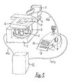
- the microscope 1 shows an arrangement for micromanipulating biological objects, which is based on an inverted microscope 1.
- the microscope 1 is shown in a highly schematic manner in order to achieve a clear overview of the representation.
- a lens changing device 2 with a plurality of lenses 3 is arranged on the microscope 1.
- a motorized microscope stage 4 for holding biological objects (not shown here) is arranged on the inverse microscope 1 above the objectives 3.
- the microscope stage 4 has an internal opening 5 through which the biological objects can be illuminated and viewed in transmitted light.
- an illumination beam path with a condenser (neither of which is shown) is arranged above the microscope stage 4.
- Adapters 6 attached, which is provided for the attachment of micromanipulators.
- a motorized micromanipulator 7 is arranged on this adapter 6. The drives for the movement of the micromanipulator 7 in the three spatial directions x, y, and z are not shown for simplicity.
- a common control panel 8 is provided for the microscope 1 and the micromanipulator 7.
- the control panel 8 has a plurality of control elements 9 for operating the motor-adjustable microscope functional elements and the motorized micromanipulator 7.
- the term "motor-adjustable microscope functional elements" is to be understood as an overarching collective name for all functional elements on the microscope that are motor-adjustable. In the example shown, this can be both the objective changing device 2 and the motorized microscope stage 4.
- the control elements 9 can each be assigned to specific microscope functional elements or specific functions of the micromanipulator 7. However, it is also conceivable to assign an operating element 9 to a plurality of functional elements or micromanipulator functions, in which case the desired function can be activated.
- the control panel 8 additionally has a display element 10 (for example an LCD display) with which the addressed microscope functional elements or the settings made can be displayed on the inverted microscope 1 or on the micromanipulator 7.
- the control panel 8 is connected to a control line 11 a with the motorized micromanipulator 7 and to a control line 11 b with a separately arranged control unit 12.
- This control unit 12 is in turn connected to a control line 11c with the motorized microscope functional elements in the microscope 1.
- This control unit 12 serves to network the motor-adjustable microscope functional elements and the motor-adjustable micromanipulator 7 and the common control panel 8. It is of course also possible to integrate the control unit 12 either in the control panel 8 or in the inverted microscope 1. However, since the control unit 12 emits considerable heat, In the embodiment of the arrangement for micromanipulating biological objects shown here, the control unit 12 is arranged separately. In Fig.
- control unit 12 it appears as if this control unit 12 were on the same laboratory table as the microscope 1 and the control panel 8. However, this is only shown for reasons of clarity. In reality, the control unit 12 is placed as far away from the microscope 1 as possible, for example under the laboratory table. The control panel 8 is then also easily and ergonomically accessible for a user of the arrangement according to the invention.
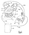
- FIG. 2 shows an arrangement for micromanipulating biological objects, which is equipped with a second micromanipulator compared to the representation in FIG. 1.
- An inverted microscope 1 has an objective changing device 2 with a plurality of objectives 3 attached to it and a motorized microscope stage 4. For reasons of clarity of the illustration, an illumination beam path with a condenser arranged above the microscope table 4 was not shown here.
- An adapter 6 is attached to the microscope 1 and is used to fasten micromanipulators.
- a first motorized micromanipulator 7 and a second motorized micromanipulator 13 are attached to this adapter 6. Both micromanipulators 7, 13 can be moved in the three spatial directions x, y and z. They are used to hold injectors (not shown here) with which biological objects can be manipulated. The type of manipulation can include the injection or suction of liquids or cell components or similar interventions.
- the microscope 1 with its motorized microscope functional elements, here the motorized lens changing device 2 and the motorized microscope stage 4, and the two micromanipulators 7 and 13 are assigned a common control panel 8.
- This control panel 8 is connected to a control line 11a with the first motorized micromanipulator 7 and by means of a control line 11d connected to the second motorized micromanipulator 13.
- the arrangement is assigned a control unit 12 which is connected to the control panel 8 with a control line 11b and to the microscope 1 with a control line 11c. H. is connected to the motorized microscope functional elements.
- the control unit 12 networks the functional elements of the microscope 1 addressed by the control panel 8 and the controlled micromanipulators 7, 13.
- memories data memory or image memory
- the control panel 8 has a plurality of control elements 9, which are assigned to the various motor-operated functional elements of the microscope 1 and / or the two micromanipulators 7, 13 (or only one of them). Details of the controls are described in Fig. 4.
- the type of networking of microscope 1, micromanipulators 7, 13, control panel 8 and control unit 12 shown can also be done differently than in the manner shown here. The type of networking depends, for example, on the interfaces or data transmission protocols used.
- the control unit 12 can also be integrated into the microscope 1 or the control panel 8. However, in order to keep undesired heat development away from the microscope 1, a separate installation of the control unit 12 was preferred in the arrangement shown here.
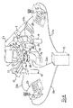
- FIG. 3 shows an arrangement according to the invention for micromanipulating biological objects, in which two control panels are provided for a microscope with two assigned micromanipulators.
- An upright microscope 14 has a motorized lens changing device 2 with a plurality of lenses 3 arranged thereon.
- a motorized microscope stage 4 (drives not shown) is used to hold a vessel 15 with biological objects 16 located thereon
- a lamp house 17 arranged on the microscope 14 emits an illumination beam path (not shown here) which is directed onto the biological objects 16 by a condenser 18.
- a first motorized micromanipulator 7 and a second motorized micromanipulator 13 are provided for manipulating the biological objects 16. In the example shown here, they are fastened separately from the microscope on support elements 19 which are not connected to the microscope. However, it is also conceivable to connect the micromanipulators to the microscope in the manner already shown in FIGS. 1 and 2, that is to say by means of an adapter directly on the microscope.
- a first injector 20 is arranged on the first motorized micromanipulator 7 and a second injector 21 is arranged on the second motorized micromanipulator 13.
- the necessary pressure control devices for controlling the pressure in the injectors 20, 21 are not shown for the sake of simplicity.
- the manipulations on the biological objects are carried out with microcapillaries 22 which are connected to the injectors 20, 21.
- the tip of the microcapillary 22 that is being controlled must be positioned exactly.
- the arrangement has a first control panel 23 and a second control panel 24.
- the first control panel 23 is connected to the first micromanipulator 7 by a control line 25a.
- the second control panel 24 is connected to the second micromanipulator 13 by a control line 25b.
- the arrangement has a control unit 12 which networks these components of the arrangement with one another.
- the control unit 12 is connected to a control line 26a with the first control panel 23, with a control line 26b with the second control panel 24 and with a control line 26c with the microscope 14 or the motorized motor-controlled microscope functional elements.
- the control unit 12 is designed so that the operation of the microscope 14 or its motorized microscope functional elements (here the motorized microscope stage 4 and the motorized lens changing device 2) and the two micromanipulators 7 and 13 alternatively both from the first control panel 23 and can take place from the second control panel 24.
- the two control panels 23, 24 have a series of control elements 9, which are or can be assigned to the various motorized functions on the microscope 14 or the micromanipulators 7, 13. Details of the control elements 9 are described in FIG. 5.
- the control unit 12 can be integrated in the microscope 14 or in one or both of the control panels 23, 24. However, since the control unit 12, which contains electronics, generates a considerable amount of heat, the control unit 12 was set up separately in the arrangement shown here. This avoids unnecessary heating of the biological elements 16. Another advantage of the separate arrangement of the control unit 12 is that the microscope 14 with the micromanipulators 7, 13 arranged next to it can be introduced into a small, spatially limited climatic chamber (not shown here) while the control unit 12 is arranged outside the climatic chamber.
- FIG. 4 shows a variant of the arrangement that has already been described in FIG. 3.
- the arrangement consists of an upright microscope with a manually operated microscope stage 28, an objective changing device 2 with several objectives 3 attached to it and a first micromanipulator 7 and a second micromanipulator 13.
- the microscope functional elements and the micromanipulators 7 and 13 are operated by means of a first common control panel 23 and a second common control panel 24.
- the arrangement is networked with a control unit 12. This is with a control line 26a with the first control panel 23, with a control line 26b with the second control panel 24 and with a control line 26c the microscope 14 and thus its microscope functional elements connected.
- the transmitted light illumination of the biological objects 16 in the vessel 15 takes place with an illumination beam path emanating from a lamp house 17, which is directed onto the biological objects by a condenser 18.
- the embodiment of the arrangement according to the invention shown here has an additional light source. It is a laser 27, the laser beam of which is coupled into an incident light beam path (not shown here) in the upper region of the microscope 14 and is focused on the biological objects with one of the objectives 3.
- the laser can be either a UV or an IR laser. If the biological objects are to be processed using laser cutting (laser microdissection), a UV laser is used. The UV laser beam is then used in the focused state for cutting on the biological objects. Alternatively, an IR laser can be used, the laser beam of which can also be focused on a biological object 16 with an objective 3. The biological object 16 (or parts thereof) captured by the focus of the IR laser beam is drawn into this laser focus and can then be held by moving the laser focus and moved with the laser focus. This principle is often referred to as "optical tweezers". To control the UV laser and / or the IR laser, an operating element 9, which serves to control the laser functions, is arranged on at least one of the control panels 23, 24. The laser functions can be: switching on / off or controlling the pulse rate (with pulsed lasers) or focus / defocus at the location of the biological objects or increasing / decreasing the intensity.
- control panels 23 and 24 can have different control elements 9. However, it has proven to be advantageous if the two control panels 23, 24 are constructed identically, so that all functions that can be addressed by means of the control elements 9 both with the left hand as well as the right hand of the user of the arrangement can be addressed.
- FIG. 5 shows an arrangement according to the invention with an inverted microscope 1 which has a motorized microscope stage 4.
- a transmitted light illumination beam path emanating from a lamp house 17 is directed by a condenser 18, which is motorized here, onto biological objects 16 which are arranged on a specimen slide 29.
- a plurality of objectives 3 are arranged on an objective changing device 2.
- the microscope image of the biological objects 16 can be observed visually by means of eyepieces 30.
- a first micromanipulator 7 and a second micromanipulator 13 are arranged on the microscope 1.
- the arrangement has two control panels 23 and 24 for operating the microscope functional elements and the two micromanipulators 7, 13.
- the control panel 23 is connected to the micromanipulator 7 with a control line 25a and the control panel 24 is connected to the micromanipulator 13 with a control line 25b.
- the arrangement is assigned to a control unit 12 for networking the control panels 23, 24, the microscope 1 with its microscope functional elements and the two micromanipulators 7, 13.
- the control unit 12 is connected to the control panel 23 with a control line 26a, to the control panel 24 with a control line 26 and to the microscope 1 with a control line 26c.
- Several control elements 9 are arranged on the control panels 23 and 24, which allow the microscope functional elements and the two micromanipulators 7 and 13 to be operated.
- the microscope 1 also has control elements 9 for actuating its microscope functional elements. In this way, it is possible to operate certain functions both from one of the control panels 23 or 24 and from the microscope 1.
- both the control panel 23 and the control panel 24 and the microscope 1 have one z drive button 31 for focusing the microscope.
- the technical implementation of the focusing can consist in the height adjustment of the microscope table 4 or in the height adjustment of the objectives 3 or the objective changing device 2.
- the microscope 1 is equipped with a fluorescent lamp house 32.
- a motorized fluorescence filter slide 33 is arranged in the fluorescence beam path (not shown) emanating from this fluorescent lamp house 32.
- a tube lens changing device 34 is arranged with a plurality of tube lenses attached thereon. Since the tube lenses with the lenses 3 represent a compensation system with regard to the image correction of the microscope image, the appropriate tube lens must be assigned to the correct lens 3.
- the motorized tube lens changing device 34 makes it possible for the user to conveniently carry out this assignment at any time.
- a plurality of video outputs 35 are attached in the imaging beam path.
- a camera adapter and a camera are attached to these video outputs 35.
- the microscope image is then transferred to the camera and can be displayed on a monitor.
- a motorized video output control (not shown here) is provided in the lower part of the microscope 1.
- the partial deflection of the imaging light can take place by means of motor-driven prisms or filters or beam splitters, in that either an intensity distribution of the imaging light or a color division (ie by selection of certain wavelength ranges) is carried out.
- This video output control can be operated by a respective assigned control element 9 be carried out both on the control panel 23 and the control panel 24.
- the microscope 1 has a motorized transmitted light filter changing device 36. It allows the motorized insertion or removal of color filters, gray filters etc. in the transmitted light beam path. It is operated by an assigned control element 9 on the control panel 23 and / or the control panel 24.
- control panels 23 and 24 can be constructed differently, but advantageously have the same functional elements. So they each have a display element 10, the z. B. can be designed as a pure LCD display, but can also be designed as an interactive display with touch surfaces. Furthermore, the control panels 23 and 24 in the embodiment shown here have a control wheel 37, which can be used, for example, to control the brightness or to adjust incrementally when focusing the lenses or to actuate the z-movement of the micromanipulators 7 and 13. An operating lever 38, which is movable in the manner of a joystick, can optionally be used to control the xy movement of the microscope stage 4 or the xy movement of the micromanipulators 7 and / or 13.
- both the control wheel 37 and the control lever 38 have a double assignment or even multiple assignment with functions.
- the desired function can be activated, for example, by operating one or more of the buttons 39.
- Other of these buttons 39 can be used, for example, to actuate the motorized lens changing device 2 or to select or control certain manipulator operating states.
- the display element 10 serves as an orientation for the user when selecting the desired control element. So the activated operating state, for. B. selected focus position of the capillary tip or selected lens or selected manipulator operating state, can be displayed, and in addition, this can be done on the multiple controls (such as for example, the control wheel 37 or the control lever 38) activated microscope functional element or the currently activated function of the micromanipulators 7 and 13 are displayed.
- An embodiment of the arrangement according to the invention has proven to be particularly advantageous in which a so-called priority monitoring of the two control panels 23 and 24 is carried out by means of the control unit 12. It is recognized by the control unit 12 when, for example, a certain function is placed on the control lever 38 on the control panel 23. This can be done, for example, by pressing buttons, but this can also be done by monitoring the commissioning of the operating lever 38. As soon as the control unit 12 has registered that, for example, the operating lever 38 has been activated for the function "move microscope table in x-direction or y-direction", the other control panel, ie. H. on the control panel 24, this function also placed on the corresponding control lever 38.
Landscapes
- Physics & Mathematics (AREA)
- Chemical & Material Sciences (AREA)
- Analytical Chemistry (AREA)
- General Physics & Mathematics (AREA)
- Optics & Photonics (AREA)
- Microscoopes, Condenser (AREA)
- Manipulator (AREA)
Applications Claiming Priority (2)
| Application Number | Priority Date | Filing Date | Title |
|---|---|---|---|
| DE10136481A DE10136481A1 (de) | 2001-07-27 | 2001-07-27 | Anordnung zum Mikromanipulieren von biologischen Objekten |
| DE10136481 | 2001-07-27 |
Publications (1)
| Publication Number | Publication Date |
|---|---|
| EP1279986A1 true EP1279986A1 (fr) | 2003-01-29 |
Family
ID=7693211
Family Applications (1)
| Application Number | Title | Priority Date | Filing Date |
|---|---|---|---|
| EP02102053A Ceased EP1279986A1 (fr) | 2001-07-27 | 2002-07-23 | Dispositif pour la micro - manipulation de specimens biologiques |
Country Status (4)
| Country | Link |
|---|---|
| US (2) | US20030021017A1 (fr) |
| EP (1) | EP1279986A1 (fr) |
| JP (1) | JP2003084209A (fr) |
| DE (1) | DE10136481A1 (fr) |
Cited By (5)
| Publication number | Priority date | Publication date | Assignee | Title |
|---|---|---|---|---|
| DE102005004680A1 (de) * | 2005-02-02 | 2006-08-10 | Carl Zeiss Jena Gmbh | Einrichtung zur Kippung des Beleuchtungsträgers an inversen Lichtmikroskopen |
| EP1801198A1 (fr) * | 2005-12-22 | 2007-06-27 | Fujitsu Ltd. | Appareil d'injection et procédé |
| WO2007098911A1 (fr) * | 2006-02-28 | 2007-09-07 | Carl Zeiss Mikrolmaging Gmbh | Unité de commande pour dispositifs de représentation optiqueS |
| WO2008089928A1 (fr) * | 2007-01-27 | 2008-07-31 | Eppendorf Ag | Procédé permettant, en particulier, l'examen optique de la surface d'un support d'échantillon pour des objets biologiques |
| US7701211B2 (en) | 2004-12-22 | 2010-04-20 | Koninklijke Philips Electronics N.V. | Magnetic resonance imaging system and method |
Families Citing this family (24)
| Publication number | Priority date | Publication date | Assignee | Title |
|---|---|---|---|---|
| DE10136572B4 (de) * | 2001-07-27 | 2005-11-17 | Eppendorf Ag | Vorrichtung zur optisch kontrollierten Mikromanipulation von biologischen Objekten |
| DE502004001262D1 (de) * | 2003-09-23 | 2006-10-05 | Evotec Technologies Gmbh | Klimakammer für mikroskope |
| JP4578814B2 (ja) * | 2004-01-26 | 2010-11-10 | 晴夫 高林 | 標的対象物の自動探索回収装置 |
| JP4576876B2 (ja) * | 2004-05-10 | 2010-11-10 | 株式会社ニコン | 顕微鏡システム |
| US20050280892A1 (en) * | 2004-05-28 | 2005-12-22 | Nobuyuki Nagasawa | Examination method and examination apparatus |
| DE102004034848B4 (de) * | 2004-07-19 | 2006-05-18 | Leica Microsystems Cms Gmbh | Inverses Mikroskop |
| US20060050376A1 (en) * | 2004-09-02 | 2006-03-09 | Houston Edward S | Robotic microscopy apparatus for high throughput observation of multicellular organisms |
| JP4894199B2 (ja) * | 2005-02-17 | 2012-03-14 | 富士通株式会社 | 物質注入装置 |
| WO2007034796A1 (fr) * | 2005-09-26 | 2007-03-29 | National University Corporation Hamamatsu University School Of Medicine | Système d’observation/d’inspection de cellule de microscope utilisant une pluralité de techniques d’observation |
| JP4757023B2 (ja) * | 2005-12-28 | 2011-08-24 | 富士通株式会社 | インジェクション装置およびインジェクション方法 |
| DE102006009564B4 (de) * | 2006-02-28 | 2014-05-15 | Carl Zeiss Microscopy Gmbh | Verfahren zur Bearbeitung einer Masse mittels eines Laserstrahls und entsprechende Vorrichtung |
| DE102006034990A1 (de) * | 2006-07-28 | 2008-01-31 | P.A.L.M. Microlaser Technologies Gmbh | Verfahren und Vorrichtung zum Bearbeiten von biologischen Objekten |
| US20080254530A1 (en) | 2007-02-27 | 2008-10-16 | Gettysburg College | Isolation and characterization of a single mitochondrion |
| JP2009136261A (ja) * | 2007-12-10 | 2009-06-25 | Olympus Corp | チップ駆動装置 |
| AU2008343383B2 (en) * | 2007-12-27 | 2013-08-29 | Cytyc Corporation | Apparatus for single-handed control of microscope functions |
| AT506233B1 (de) * | 2008-01-18 | 2009-07-15 | Leica Mikrosysteme Gmbh | Mikromanipulator für ein kryomikrotom |
| DE202009017670U1 (de) * | 2009-12-27 | 2010-04-29 | Märzhäuser Wetzlar GmbH & Co. KG | Mikroskop-Steuereinheit |
| EP2378341A1 (fr) * | 2010-04-15 | 2011-10-19 | Mmi Ag | Procédé de positionnement sans collision d'un outil de micromanipulation |
| GB2543273A (en) | 2015-10-12 | 2017-04-19 | Leica Microsystems Cambridge Ltd | Obtaining biological information and storing and searching biological information in a database |
| JP7082482B2 (ja) | 2017-12-20 | 2022-06-08 | オリンパス株式会社 | ディスク走査型顕微鏡システム、プログラム |
| JP6956236B2 (ja) * | 2019-08-14 | 2021-11-02 | 憲隆 福永 | 顕微授精訓練装置 |
| JP6725735B1 (ja) * | 2019-08-21 | 2020-07-22 | 憲隆 福永 | 顕微授精用装置および顕微授精用術具の位置制御方法 |
| CN111751974B (zh) * | 2020-07-31 | 2022-02-01 | 临沂大学 | 一种具有多向水平微调功能的盒式显微镜 |
| US20230059331A1 (en) * | 2021-08-04 | 2023-02-23 | City University Of Hong Kong | Automated system for high-throughput microinjection of adherent cells |
Citations (5)
| Publication number | Priority date | Publication date | Assignee | Title |
|---|---|---|---|---|
| DE3718066A1 (de) * | 1987-05-29 | 1988-12-08 | Zeiss Carl Fa | Verfahren zur mikroinjektion in zellen bzw. zum absaugen aus einzelnen zellen oder ganzer zellen aus zellkulturen |
| EP0365928A2 (fr) * | 1988-10-28 | 1990-05-02 | Firma Carl Zeiss | Procédé pour l'exploitation d'images de cellules |
| US5363190A (en) * | 1992-09-07 | 1994-11-08 | Olympus Optical Co., Ltd. | Method and apparatus for optical micro manipulation |
| DE19504663A1 (de) * | 1994-02-15 | 1995-08-17 | Shimadzu Corp | Mikromanipulatoranordnung |
| WO1998014816A1 (fr) * | 1996-10-02 | 1998-04-09 | Cell Robotics Inc. | Microscope a fenetre pour laser |
Family Cites Families (17)
| Publication number | Priority date | Publication date | Assignee | Title |
|---|---|---|---|---|
| US2857808A (en) * | 1954-02-05 | 1958-10-28 | John A Hastings | Micromanipulator |
| DE3122098A1 (de) * | 1981-06-03 | 1983-01-05 | Siemens AG, 1000 Berlin und 8000 München | Roentgendiagnostikanlage fuer angiographische roentgenuntersuchungen |
| JPH0760219B2 (ja) * | 1985-02-25 | 1995-06-28 | オリンパス光学工業株式会社 | マニピユレ−タ付倒立型顕微鏡 |
| US4695137A (en) * | 1986-02-26 | 1987-09-22 | Carl-Zeiss-Stiftung, Heidenheim/Brenz | Motorized focus drive for a microscope |
| IL84255A (en) * | 1987-10-23 | 1993-02-21 | Galram Technology Ind Ltd | Process for removal of post- baked photoresist layer |
| DE3808531C1 (fr) * | 1988-03-15 | 1989-07-13 | Eppendorf - Netheler - Hinz Gmbh, 2000 Hamburg, De | |
| JP3223583B2 (ja) * | 1992-06-29 | 2001-10-29 | 株式会社島津製作所 | マイクロマニピュレータ用操作装置 |
| US5456880A (en) * | 1992-11-20 | 1995-10-10 | Shimadzu Corporation | Micropipet apparatus and micromanipulator |
| JP3537194B2 (ja) * | 1994-10-17 | 2004-06-14 | オリンパス株式会社 | 光学顕微鏡 |
| DE19548091A1 (de) * | 1995-01-11 | 1996-07-25 | Zeiss Carl Fa | Einhand-Steuerelement für Bewegungssteuerungen, vorzugsweise von optischen Instrumenten |
| JP3537205B2 (ja) * | 1995-02-02 | 2004-06-14 | オリンパス株式会社 | 顕微鏡装置 |
| US5620857A (en) * | 1995-06-07 | 1997-04-15 | United States Of America, As Represented By The Secretary Of Commerce | Optical trap for detection and quantitation of subzeptomolar quantities of analytes |
| JP3427366B2 (ja) * | 1995-08-17 | 2003-07-14 | 株式会社ナリシゲ | 微動操作用ジョイスティックにおける微動率の調整機構 |
| WO1997029354A1 (fr) * | 1996-02-05 | 1997-08-14 | Bayer Aktiengesellschaft | Procede et dispositif pour trier et recuperer des objets biologiques deposes sur un support plat, tels que des cellules biologiques ou des organites cellulaires, des coupes histologiques, des particules de chromosomes etc., au moyen de faisceaux laser |
| DE19740324C2 (de) * | 1997-09-13 | 2003-05-28 | Eppendorf Ag | Einrichtung zum Manipulieren von zytotechnischen Instrumenten |
| JP4397993B2 (ja) * | 1999-03-24 | 2010-01-13 | オリンパス株式会社 | 顕微鏡写真撮影装置 |
| US20020149628A1 (en) * | 2000-12-22 | 2002-10-17 | Smith Jeffrey C. | Positioning an item in three dimensions via a graphical representation |
-
2001
- 2001-07-27 DE DE10136481A patent/DE10136481A1/de not_active Withdrawn
-
2002
- 2002-07-23 EP EP02102053A patent/EP1279986A1/fr not_active Ceased
- 2002-07-25 US US10/205,090 patent/US20030021017A1/en not_active Abandoned
- 2002-07-29 JP JP2002219844A patent/JP2003084209A/ja not_active Ceased
-
2007
- 2007-01-22 US US11/625,498 patent/US20070177258A1/en not_active Abandoned
Patent Citations (5)
| Publication number | Priority date | Publication date | Assignee | Title |
|---|---|---|---|---|
| DE3718066A1 (de) * | 1987-05-29 | 1988-12-08 | Zeiss Carl Fa | Verfahren zur mikroinjektion in zellen bzw. zum absaugen aus einzelnen zellen oder ganzer zellen aus zellkulturen |
| EP0365928A2 (fr) * | 1988-10-28 | 1990-05-02 | Firma Carl Zeiss | Procédé pour l'exploitation d'images de cellules |
| US5363190A (en) * | 1992-09-07 | 1994-11-08 | Olympus Optical Co., Ltd. | Method and apparatus for optical micro manipulation |
| DE19504663A1 (de) * | 1994-02-15 | 1995-08-17 | Shimadzu Corp | Mikromanipulatoranordnung |
| WO1998014816A1 (fr) * | 1996-10-02 | 1998-04-09 | Cell Robotics Inc. | Microscope a fenetre pour laser |
Non-Patent Citations (1)
| Title |
|---|
| SONEK G J ET AL: "IN SITU MICROPARTICLE ANALYSIS OF MARINE PHYTOPLANKTON CELLS WITH INFRARED LASER-BASED OPTICAL TWEEZERS", APPLIED OPTICS, OPTICAL SOCIETY OF AMERICA,WASHINGTON, US, vol. 34, no. 33, 20 November 1995 (1995-11-20), pages 7731 - 7741, XP000537278, ISSN: 0003-6935 * |
Cited By (5)
| Publication number | Priority date | Publication date | Assignee | Title |
|---|---|---|---|---|
| US7701211B2 (en) | 2004-12-22 | 2010-04-20 | Koninklijke Philips Electronics N.V. | Magnetic resonance imaging system and method |
| DE102005004680A1 (de) * | 2005-02-02 | 2006-08-10 | Carl Zeiss Jena Gmbh | Einrichtung zur Kippung des Beleuchtungsträgers an inversen Lichtmikroskopen |
| EP1801198A1 (fr) * | 2005-12-22 | 2007-06-27 | Fujitsu Ltd. | Appareil d'injection et procédé |
| WO2007098911A1 (fr) * | 2006-02-28 | 2007-09-07 | Carl Zeiss Mikrolmaging Gmbh | Unité de commande pour dispositifs de représentation optiqueS |
| WO2008089928A1 (fr) * | 2007-01-27 | 2008-07-31 | Eppendorf Ag | Procédé permettant, en particulier, l'examen optique de la surface d'un support d'échantillon pour des objets biologiques |
Also Published As
| Publication number | Publication date |
|---|---|
| JP2003084209A (ja) | 2003-03-19 |
| DE10136481A1 (de) | 2003-02-20 |
| US20070177258A1 (en) | 2007-08-02 |
| US20030021017A1 (en) | 2003-01-30 |
Similar Documents
| Publication | Publication Date | Title |
|---|---|---|
| EP1279986A1 (fr) | Dispositif pour la micro - manipulation de specimens biologiques | |
| EP1946173B1 (fr) | Dispositif de manipulation d'echantillons | |
| EP1186879B1 (fr) | Procédé et dispositif de microdissection laser | |
| DE2922212A1 (de) | Mikromanipulator fuer mikroskope | |
| EP1186878B1 (fr) | Procédé et dispositif de microdissection Laser | |
| AT405463B (de) | Computerunterstütztes video-mikroskop | |
| DE10332468B4 (de) | Mikroskop und Verfahren zur Bedienung eines Mikroskops | |
| WO2019179845A1 (fr) | Système à microscope et procédé servant à commander un système de microscope de ce type | |
| DE10051299A1 (de) | Mikroskop mit multifunktionalen Bedienelementen | |
| DE102012220195A1 (de) | Mikroskop | |
| EP1533643B1 (fr) | Dispositif d'observation à unité de commande séparée | |
| DE20221696U1 (de) | Anordnung | |
| DE3933064C2 (de) | Steuervorrichtung für ein Mikroskop | |
| EP1064581B1 (fr) | Microscopie video | |
| DE10136572B4 (de) | Vorrichtung zur optisch kontrollierten Mikromanipulation von biologischen Objekten | |
| DE20221677U1 (de) | Anordnung zum Mikromanipulieren von biologischen Objekten | |
| DE10137964B4 (de) | Mikroskop mit umschaltbarer Beleuchtung in mindestens zwei Spektralbereichen und Vorrichtung zur Beleuchtungsumschaltung | |
| DE102013209964B4 (de) | Lasermikrodissektionssystem mit Benutzerinformationseinheit und Verfahren zur Lasermikrodissektion | |
| DE102004034848B4 (de) | Inverses Mikroskop | |
| WO2000008509A1 (fr) | Ensemble microscope | |
| DE102005035546A1 (de) | Verfahren zum Objektivwechsel und Objektivwechselvorrichtung für Mikroskope | |
| DE102005024998A1 (de) | Modulare Einheit zur Verteilung des Lichtstroms einer Kaltlichtquelle | |
| DE102017217385A1 (de) | Optisches Beobachtungsgerät |
Legal Events
| Date | Code | Title | Description |
|---|---|---|---|
| PUAI | Public reference made under article 153(3) epc to a published international application that has entered the european phase |
Free format text: ORIGINAL CODE: 0009012 |
|
| AK | Designated contracting states |
Designated state(s): AT BE BG CH CY CZ DE DK EE ES FI FR GB GR IE IT LI LU MC NL PT SE SK TR |
|
| AX | Request for extension of the european patent |
Extension state: AL LT LV MK RO SI |
|
| 17P | Request for examination filed |
Effective date: 20030215 |
|
| AKX | Designation fees paid |
Designated state(s): DE FR GB |
|
| 17Q | First examination report despatched |
Effective date: 20040414 |
|
| RAP1 | Party data changed (applicant data changed or rights of an application transferred) |
Owner name: LEICA MICROSYSTEMS CMS GMBH |
|
| APBN | Date of receipt of notice of appeal recorded |
Free format text: ORIGINAL CODE: EPIDOSNNOA2E |
|
| APBR | Date of receipt of statement of grounds of appeal recorded |
Free format text: ORIGINAL CODE: EPIDOSNNOA3E |
|
| APAF | Appeal reference modified |
Free format text: ORIGINAL CODE: EPIDOSCREFNE |
|
| APBT | Appeal procedure closed |
Free format text: ORIGINAL CODE: EPIDOSNNOA9E |
|
| STAA | Information on the status of an ep patent application or granted ep patent |
Free format text: STATUS: THE APPLICATION HAS BEEN REFUSED |
|
| 18R | Application refused |
Effective date: 20090126 |