EP1261507B1 - Lenkrad für kraftfahrzeuge mit einer schalteinrichtung zum betätigen einer elektrischen funktionsgruppe eines kraftfahrzeugs - Google Patents
Lenkrad für kraftfahrzeuge mit einer schalteinrichtung zum betätigen einer elektrischen funktionsgruppe eines kraftfahrzeugs Download PDFInfo
- Publication number
- EP1261507B1 EP1261507B1 EP01919206A EP01919206A EP1261507B1 EP 1261507 B1 EP1261507 B1 EP 1261507B1 EP 01919206 A EP01919206 A EP 01919206A EP 01919206 A EP01919206 A EP 01919206A EP 1261507 B1 EP1261507 B1 EP 1261507B1
- Authority
- EP
- European Patent Office
- Prior art keywords
- contact
- steering wheel
- wheel according
- contact elements
- another
- Prior art date
- Legal status (The legal status is an assumption and is not a legal conclusion. Google has not performed a legal analysis and makes no representation as to the accuracy of the status listed.)
- Expired - Lifetime
Links
Images


Classifications
-
- B—PERFORMING OPERATIONS; TRANSPORTING
- B60—VEHICLES IN GENERAL
- B60Q—ARRANGEMENT OF SIGNALLING OR LIGHTING DEVICES, THE MOUNTING OR SUPPORTING THEREOF OR CIRCUITS THEREFOR, FOR VEHICLES IN GENERAL
- B60Q5/00—Arrangement or adaptation of acoustic signal devices
- B60Q5/001—Switches therefor
- B60Q5/003—Switches therefor mounted on the steering wheel
-
- H—ELECTRICITY
- H01—ELECTRIC ELEMENTS
- H01H—ELECTRIC SWITCHES; RELAYS; SELECTORS; EMERGENCY PROTECTIVE DEVICES
- H01H1/00—Contacts
- H01H1/12—Contacts characterised by the manner in which co-operating contacts engage
- H01H1/14—Contacts characterised by the manner in which co-operating contacts engage by abutting
- H01H1/18—Contacts characterised by the manner in which co-operating contacts engage by abutting with subsequent sliding
Definitions
- the invention relates to a steering wheel for motor vehicles a switching device for actuating an electrical Functional group of a motor vehicle according to the preamble of claim 1, see US-A-5 338 906.
- the problem with such a switching device is that that the contact elements get dirty over time or from be coated with an oxide layer, which is the functionality the switching device impaired. This applies especially when using the switching device Relay to be controlled or a control signal on an electronic device is to be delivered, whereupon the horn device is triggered. In these cases flow over the two contact elements of the switching device only weak currents with a current in the The order of 20 mA at a voltage of the order from 5 V to 12 V. The pollution or oxidation of the Contact elements then have a particularly disadvantageous effect.
- the invention has for its object a steering wheel for Motor vehicles with a switching device for actuation an electrical functional group of a motor vehicle to create the kind mentioned above, which is characterized by a distinguishes increased functional reliability.
- the switching device is so resiliently mounted, that it slides along the other contact element after the two contact elements under the for making electrical contact, i.e. to close the switching device, applied force in contact with each other have been brought.
- the two contact elements of the switching device are on two movable to make contact with each other, supporting assemblies of the steering wheel attached.
- the spring-mounted contact element is a elastic element with the associated load-bearing assembly, e.g. connected to the contact carrier.
- the second direction preferably essentially runs perpendicular to the first direction.
- the contact surfaces of the two contact elements extend each essentially perpendicular to the first Direction along which the two contacts face each other are movable.
- One of the contact elements on an assembly of the steering wheel skeleton is advantageous set and the other contact element an assembly that is movable with respect to the steering wheel skeleton stored.
- the assembly movable with respect to the steering wheel comprises preferably a contact carrier and is over a elastic element resiliently connected to the steering wheel skeleton.
- the elastic Element can be integrally molded onto the contact element be as well as a separate, on the contact element attached elastic element can be formed.
- the elastic element is preferably under tension, around a defined positioning of the contact element and thus also a defined distance from the other Ensure contact element.
- the elastic element has one leg up at an acute angle to the direction of movement along which the two Contact elements can be brought into contact with each other.
- This angle is preferably chosen such that the Angle between the said leg of the elastic Element and the contact surface of the contact element at least Is 45 °.
- the leg of the elastic element attached the associated contact element and the other end of the leg is attached to the corresponding load-bearing assembly, e.g. the contact carrier. It supports itself the leg preferably on a support element of the load-bearing Assembly from, this assembly on the one hand in one piece can be integrally formed on the leg or alternatively forms an inclined plane on which the leg of the elastic Element is applied.
- the leg of the elastic element preferably with its end facing away from the contact element stored in a point-shaped bearing point in cross section, so that it can be swiveled.
- stops can be provided which interact, around the movement of the two contact elements to one another limit and thus also limit the force that the Exercise the maximum of two contact elements on each other. in this connection is the distance between the two contact elements in the direction of movement smaller than the distance between the two stops this direction; because the two stops must allow that the two contact elements are in contact with each other kick and then parallel to each other move before by a meeting of the two Stops further movement is prevented.
- the contact carrier preferably consists of a conductive Material and is connected to a connector, so that the contact carrier on a defined electrical Potential is feasible.
- the contact carrier can also do this be integrally formed with the connector.
- the Contact carrier and the associated to minimize the contact resistance integrally molded connector can e.g. consist of a tinned steel or brass sheet.
- the non-resilient contact is preferably around a contact rivet that has a rough, e.g. has a corrugated surface (contact surface). hereby the cleaning effect that occurs during is improved one contact surface moves along the other. This enables a reduction in the contact pressure, of the spring-mounted contact element on the other contact element must be exercised in order to be sufficient To achieve cleaning effect. This allows the Size of the for resilient mounting of a contact element serving elastic element (contact spring) reduced become.
- the spring-mounted contact element can preferably are formed by a contact plate, the stiffening ribs and / or has relief slots or bores, in order to specifically increase or reduce the contact pressure, which occurs when the two contact elements are in effect contact a defined force.
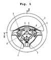
- Figures 1 and 2 is a three-spoke Steering wheel 1 shown, in the central area a plurality mechanical and electrical assemblies is visible, since the airbag module covering this area is not included is shown.
- the steering wheel 1 has a rotatable one on a steering wheel hub 8 stored steering wheel skeleton 2 with a casing 10, on which over three fasteners in the form of collar screws 3 a contact carrier 11 is attached.
- a contact carrier 11 On the collar bolts 3 is an elastic element in each case Formed a preloaded coil spring 3a, about the contact carrier 11 resiliently under pretension supports the steering wheel skeleton 2.
- switching device 4, 12 arranged to operate a bugle of the motor vehicle and which is based below of Figures 3a - 3c will be described.
- Switching device 4, 12 with the signal horn electrically being able to connect is usually one (not here shown) provided contact unit, the transmission electrical signals between two mutually movable Assemblies of a motor vehicle, namely the steering wheel on the one hand and one fixed with respect to the steering wheel Assembly, on the other hand, serves, see e.g. DE 195 06 865 C1 and DE 195 25 928 C2, where such contact units (transmission devices) are described. 1 are only the mounting screws 5 for the contact unit shown.
- FIGS. 1 and 2 An electrical cable 6 is also shown in FIGS. 1 and 2 recognizable with a connector 7 that the supply of Power to an airbag unit is used, which is provided for this purpose
- Bearings 9 of the steering wheel in a known manner is so resiliently attached that it is parallel to the steering wheel hub 8 is movable when on the central steering wheel area (which is formed by a cover cap of the airbag module pressure is exerted.
- This will in turn the contact carrier 11 parallel to the direction of extension B the steering wheel hub 8 (in the axial direction) on the steering wheel skeleton 2 moves, causing the contact elements of the switching device 4, 12 are closed, based on what follows 3a - 3c will be explained in more detail.
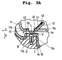
- Fig. 3a is that in Fig. 2 by a circle A around Switching device 4, 12 shown enlarged.
- the switching device 4, 12 comprises two contact elements, of which the one contact element 4 resiliently on the contact carrier 11 is mounted and the other contact element 12 formed as a contact rivet and on the steering wheel skeleton 2 is attached.
- the spring-mounted contact element 4 consists of a cylindrical contact portion 4a, the an elastic mounted on the contact carrier 11 Element in the form of a contact spring 40 is formed and has a contact surface 4b.
- Contact spring 40 has a plate-shaped end section 43 on which rests on the contact carrier 11 and with a hollow cylindrical extension 42 through a recess 11a of the Contact carrier 11 projects through, the hollow cylindrical Section 42 at its free end the contact section 4a forms with the contact surface 4b.
- From the plate-shaped Section 43 of the contact spring 40 is at an angle from about 45 ° from a spring leg 41 on a support member rests by a bent out of the contact carrier Support tab 17 is formed and the one inclined plane forms as a support for the spring leg 41.
- the spring leg 41 linear (i.e. punctiform in cross-section) fixed to the support bracket 17.
- the recess 11a Such a width (extension transverse to the direction of movement B along the two contact elements 4, 12 can be brought into contact with each other), has that the hollow cylindrical portion 42 of the Spring element 40 and thus also the contact element 4 in move this recess 11a transversely to the direction of movement B. to let.
- the second contact element 12 designed as a contact rivet is attached directly to the steering wheel skeleton 2, for what a corresponding recess in the envelope 10 of the Steering wheel skeleton 2 is provided.
- the one as the contact section 12a serving and provided with a contact surface 12b Rivet head of the contact rivet 12 is thereby one surrounded hollow cylindrical portion 18 of the sheath 10.
- the hollow cylindrical section 18 of the casing 10 and the lateral edges 11b of the recess 11a of the contact element 11 are arranged opposite one another, that the movement of the contact carrier 11 relative to the Steering wheel skeleton 2 along to close the switching device 4, 12 limit the intended direction of movement B. This limits the contact force that the resilient mounted contact element 4 when closing the switching device 4, 12 on the contact element designed as a rivet contact 12 can exercise.
- the distance a between the two Stops 11b, 18 is chosen so that it is larger than the distance d between the two contact surfaces 4b, 12b along the direction of movement B. This ensures that the two stops 11b, 18 only then together interact to further move the Prevent contact elements 4, 12 after these two have come into contact.
- the distance d between the two contact surfaces 4b, 12b is defined precisely and reproducibly in that the one intended for receiving the first contact element 4 Spring element 40 under prestress on the contact carrier 11 or whose support bracket 17 supports.
- the contact carrier 11 is electrical conductive and via an electrical connection placed on a positive potential, which therefore also the Potential of the first, spring-mounted contact element 4 equivalent.
- the other, directly on the steering wheel skeleton 2 attached contact element 12 is on the other hand on a negative potential. If the contact is closed, kick that is, the two contact elements 4, 12 are connected to one another, this creates a current that e.g. a relay or a Controls electronic module and thereby the triggering of the Signal horn of the motor vehicle or another electrical actuatable module triggers.
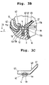
- Fig. 3b shows the switching device from Fig. 3a after Closing the contact, the two stops already 11b, 18 have come into contact with one another.
- This relative movement in which the over a in Cross-section point attachment point on the support bracket 17 attached and acting as a lever leg 41 a Swiveling movement only ends when the two Stops 11b of the contact carrier 11 on the one hand and 18 of the Envelope 10 of the steering wheel skeleton 2 on the other hand with each other have stopped.
- the extent of the relative movement of the two contact surfaces 4b, 12b perpendicular to the direction of movement B is among other things through the angle of the leg 41 with respect to the direction of movement B or the contact surface 4b (i.e. with respect to the perpendicular to Direction of movement B) determined. In the embodiment according to 3a and 3b, both angles are 45 °. Will the Angle of the leg 41 to the direction B less than 45 ° selected (and thus the angle of the leg 41 to Contact area 4b larger than 45 °), the extent of Movement of the spring-mounted contact element 4 vertically be increased to the direction B.
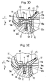
- FIGS. 3d and 3e A further development of the exemplary embodiment is shown in FIGS. 3d and 3e represented from FIGS. 3a and 3b, after which the switching device 4, 12 for protection against dust and The like.
- the switching device 4, 12 for protection against dust and The like.
- an elastically deformable hollow body in the form of a hollow cylindrical open-cell foam body 18a e.g. made of moltoprene
- the open cells enable an air exchange.
- FIGS. 4a and 4b A modification of the exemplary embodiment is shown in FIGS. 4a and 4b from Figures 3a and 3b, the differ from this embodiment in two respects different.
- the support element 47 over which there is a leg 41 the contact spring 40 is supported on the contact carrier 11, in this case in one piece on the contact spring 40 molded and via a point of attachment in cross section 45 connected to the contact carrier.
- the support element 47 is replaced by one at one end of the Leg 41 angled portion formed, which extends from the said end of the leg 41 to the contact carrier 11 extends and widens along this direction. In the transition area between leg 41 and support element 47 a relief slot is provided.
- the dome-shaped shell 19 consists of two essentially hollow cylindrical sections 19a, 19b, which are connected in one piece and by to which the one hollow cylindrical section 19a is assigned Bores 11c of the contact carrier 11 is fixed and the other section 19b on a shoulder 18a Steering wheel cover 18 supports. This extends between the steering wheel cover 18 in the region of the shoulder 18a and second section 19b of the dome-shaped casing 19 Channel 18b essentially parallel to the direction of movement B, in which the first hollow cylindrical section 19a of the dome-shaped Cover 19 can slide.
- the elasticity of the material of the dome-shaped casing 19 is that two sections 19a, 19b of the dome-shaped casing 19 both movable to each other as well as deformable and enable a movement of the two contact elements 4, 12 relative to each other along direction B to make contact.
- FIGS. 5a and 5b a contact element in the form of a contact rivet 12, whose rivet head has a contact section 12a forms with a contact surface 12b.
- the Contact surface 12b is roughened for cleaning effect improve that occurs when the contact area of a contact element along the contact surface of the other contact element moves.
- the roughened surface structure the contact surface 12b can e.g. by Embossing or sanding.
- the contact rivet 12 also has one in its shaft 12c longitudinally extending groove 12d, and the Shank 12c closes at its lower, the rivet head 12a opposite end with a tapered area 12e from.
- stops 12b, 18 allows the contact carrier still along the direction of movement B (axial Direction) can be moved further when the two contact elements 4, 12 with their contact surfaces 4b, 12b already in Stand in contact.
Description
- Fig. 1 -
- eine Draufsicht auf ein Lenkrad, dessen zentraler Lenkradbereich zur Aufnahme eines Airbagmodules dient, welches in Fig. 1 nicht dargestellt ist, um die elektrischen Baugruppen im zentralen Lenkradbereich sichtbar zu machen;
- Fig. 2 -
- einen Querschnitt entlang der Linie II - II des Lenkrades aus Fig. 1;
- Fig. 3a -
- eine vergrößerte Darstellung eines Ausschnittes aus Fig. 2, die eine elektrische Schalteinrichtung mit zwei zueinander beweglichen Kontaktelementen zeigt;
- Fig. 3b -
- die Schalteinrichtung aus Fig. 3a mit in Kontakt befindlichen Kontaktelementen;
- Fig. 3c -
- eine perspektivische Darstellung des einen Kontaktelementes aus den Figuren 3a bzw. 3b;
- Figuren 3d, 3e -
- eine Weiterbildung der Schalteinrichtung aus den Figuren 3a, 3b;
- Fig. 4a -
- eine Abwandlung der Schalteinrichtung aus den Figuren 3a und 3b;
- Fig. 4b -
- eine perspektivische Darstellung eines Kontaktelementes der Schalteinrichtung aus Fig. 4a;
- Fig. 5a -
- eine Seitenansicht eines Kontaktnietes;
- Fig. 5b -
- eine Draufsicht auf die Kontaktfläche des Kontaktnietes aus Fig. 5a.
Claims (26)
- Lenkrad für Kraftfahrzeuge mit mindestens einer Schalteinrichtung zum Betätigen einer elektrischen Funktionsgruppe eines Kraftfahrzeugs, wobei die Schalteinrichtung zwei zueinander bewegliche elektrische Kontaktelemente (4, 12) umfaßt, die zur Betätigung der Funktionsgruppe miteinander in Kontakt bringbar sind,
dadurch gekennzeichnet, daß eines der Kontaktelemente (4) derart federnd gelagert ist, daß es entlang des anderen Kontaktelementes (12) gleitet, nachdem die beiden Kontaktelemente (4, 12) zum Betätigen der elektrischen Funktionsgruppe miteinander in Kontakt gebracht worden sind, wobei die beiden Kontaktelemente (4, 12) an zwei zur Herstellung des Kontaktes zwischen den Kontaktelementen (4, 12) zueinander beweglichen tragenden Baugruppen (2, 11) des Lenkrades (1) befestigt sind und das eine Kontaktelement (4) über ein elastisches Element (40) mit der zugehörigen tragenden Baugruppe (11) verbunden ist. - Lenkrad nach Anspruch 1, dadurch gekennzeichnet, daß die beiden Kontaktelemente (4, 12) entlang einer ersten Richtung (B) aufeinander zu bewegbar sind, bis sie miteinander in Kontakt treten und daß anschließend das federnd gelagerte Kontaktelement (4) entlang einer zweiten Richtung (C) ausweicht und dabei über das andere Kontaktelement (12) gleitet.
- Lenkrad nach Anspruch 2, dadurch gekennzeichnet, daß die zweite Richtung (C) im wesentlichen senkrecht zur ersten Richtung (B) verläuft.
- Lenkrad nach Anspruch 2 oder 3, dadurch gekennzeichnet, daß die beiden Kontaktelemente (4, 12) jeweils Kontaktflächen (4b, 12b) aufweisen, die sich im wesentlichen senkrecht zu der ersten Richtung (B) erstrecken und die miteinander in Kontakt bringbar sind.
- Lenkrad nach einem der Ansprüche 1 bis 4, dadurch gekennzeichnet, daß eine der Baugruppen durch das Lenkradskelett (2) gebildet wird und daß die andere Baugruppe (11) beweglich an dem Lenkradskelett (2) gelagert ist.
- Lenkrad nach Anspruch 5, dadurch gekennzeichnet, daß die beweglich bezüglich des Lenkradskelettes (2) gelagerte Baugrupppe (11) entgegen der zur Herstellung eines Kontaktes zwischen den beiden Kontaktelementen (4, 12) dienenden ersten Bewegungsrichtung (B) elastisch vorgespannt ist.
- Lenkrad nach Anspruch 6, dadurch gekennzeichnet, daß die beweglich bezüglich des Lenkradskelettes (2) gelagerte Baugruppe (11) durch Ausübung eines Druckes auf den zentralen Lenkradbereich zur Herstellung des Kontaktes zwischen den beiden Kontaktelementen (4, 12) bewegbar ist.
- Lenkrad nach einem der Ansprüche 5 bis 7, dadurch gekennzeichnet, daß die beweglich bezüglich des Lenkradskelettes (2) gelagerte Baugruppe (11) einen Kontaktträger (11) umfaßt, der in axialer Richtung bezüglich des Lenkradskelettes beweglich ist.
- Lenkrad nach einem der Ansprüche 1 bis 8, dadurch gekennzeichnet, daß das Kontaktelement (4) einstückig an dem elastischen Element (40) angeformt ist.
- Lenkrad nach einem der Ansprüche 1 bis 9, dadurch gekennzeichnet, daß das elastische Element (40) einen Schenkel (41) aufweist, der in einem spitzen Winkel zu der ersten Richtung (B) verläuft, entlang der die beiden Kontaktelemente (4, 12) miteinander in Kontakt bringbar sind.
- Lenkrad nach Anspruch 10, dadurch gekennzeichnet, daß an einem Ende des Schenkels (41) das Kontaktelement (4) vorgesehen ist und daß das andere Ende des Schenkels (41) bezüglich der tragenden Baugruppe (11) festgelegt ist.
- Lenkrad nach Anspruch 10 oder 11, dadurch gekennzeichnet, daß sich der Schenkel (41) an einem Stützelement (17, 47) der zugehörigen tragenden Baugruppe (11) abstützt.
- Lenkrad nach Anspruch 12, dadurch gekennzeichnet, daß das Stützelement (47) einstückig an dem Schenkel (41) angeformt ist.
- Lenkrad nach einem der vorhergehenden Ansprüche, dadurch gekennzeichnet, daß das elastische Element (40) schwenkbar gelagert ist.
- Lenkrad nach einem der Ansprüche 10 bis 13 und Anspruch 14, dadurch gekennzeichnet, daß der Schenkel (41) des elastischen Elementes (40) schwenkbar gelagert ist.
- Lenkrad nach einem der Ansprüche 1 bis 15, dadurch gekennzeichnet, daß das elastische Element (40) unter Vorspannung steht.
- Lenkrad nach einem der vorhergehenden Ansprüche, dadurch gekennzeichnet, daß Anschläge (11b, 18) vorgesehen sind, die zusammenwirken, um die Bewegung der beiden Kontaktelemente (4, 12) zueinander zu begrenzen und dadurch die Kraft begrenzen, die die beiden Kontaktelemente (4, 12) aufeinander ausüben.
- Lenkrad nach Anspruch 17, dadurch gekennzeichnet, daß der Abstand (d) der beiden Kontaktelemente (4, 12) entlang der ersten Richtung (B), entlang der die beiden Kontaktelemente (4, 12) miteinander in Kontakt bringbar sind, kleiner ist als der Abstand (a) der beiden Anschläge (11b, 18) entlang dieser Richtung (B).
- Lenkrad nach einem der Ansprüche 1 bis 18, dadurch gekennzeichnet, daß das federnd gelagerte Kontaktelement (4) an der beweglichen, tragenden Baugruppe (11) des Lenkrades (1) befestigt ist.
- Lenkrad nach einem der Ansprüche 8 bis 19, dadurch gekennzeichnet, daß der Kontaktträger (11) aus einem elektrisch leitenden Material besteht und einstückig mit einem elektrischen Anschlußelement verbunden ist.
- Lenkrad nach einem der vorhergehenden Ansprüche, dadurch gekennzeichnet, daß eine Hülle (18a, 19) vorgesehen ist, die die Schalteinrichtung (4, 12) umgibt, um sie vor Verschmutzung zu schützen.
- Lenkrad nach Anspruch 21, dadurch gekennzeichnet, daß die Hülle (19) aus zwei entlang der ersten Richtung (B), entlang der die beiden Kontaktelemente (4, 12) miteinander in Kontakt bringbar sind, zueinander beweglichen Abschnitten (19a, 19b) besteht.
- Lenkrad nach Anspruch 21, dadurch gekennzeichnet, daß die Hülle (18a) aus einem entlang der ersten Richtung (B), entlang der die beiden Kontaktelemente. (4, 12) miteinander in Kontakt bringbar sind, deformierbaren Hohlkörper besteht.
- Lenkrad nach einem der vorhergehenden Ansprüche, dadurch gekennzeichnet, daß eines der Kontaktelemente (12) eine aufgerauhte Oberflächenstruktur (12b) aufweist, die als Kontaktfläche dient.
- Lenkrad nach einem der vorhergehenden Ansprüche, dadurch gekennzeichnet, daß eines der Kontaktelemente (4) plattenförmig ausgebildet ist oder an einem plattenförmigen Abschnitt angeformt ist und daß dieser Abschnitt Versteifungsrippen und/oder Ausnehmungen aufweist.
- Lenkrad nach einem der vorhergehenden Ansprüche, dadurch gekennzeichnet, daß als Material für die Kontaktelemente (4, 12) eine Silberlegierung oder Messing verwendet wird.
Applications Claiming Priority (3)
| Application Number | Priority Date | Filing Date | Title |
|---|---|---|---|
| DE20004953U DE20004953U1 (de) | 2000-03-10 | 2000-03-10 | Lenkrad für Kraftfahrzeuge mit einer Schalteinrichtung zum Betätigen einer elektrischen Funktionsgruppe eines Kraftfahrzeugs |
| DE20004953U | 2000-03-10 | ||
| PCT/DE2001/001024 WO2001066383A1 (de) | 2000-03-10 | 2001-03-12 | Lenkrad für kraftfahrzeuge mit einer schalteinrichtung zum betätigen einer elektrischen funktionsgruppe eines kraftfahrzeugs |
Publications (2)
| Publication Number | Publication Date |
|---|---|
| EP1261507A1 EP1261507A1 (de) | 2002-12-04 |
| EP1261507B1 true EP1261507B1 (de) | 2004-05-06 |
Family
ID=33103726
Family Applications (1)
| Application Number | Title | Priority Date | Filing Date |
|---|---|---|---|
| EP01919206A Expired - Lifetime EP1261507B1 (de) | 2000-03-10 | 2001-03-12 | Lenkrad für kraftfahrzeuge mit einer schalteinrichtung zum betätigen einer elektrischen funktionsgruppe eines kraftfahrzeugs |
Country Status (7)
| Country | Link |
|---|---|
| US (1) | US6803533B2 (de) |
| EP (1) | EP1261507B1 (de) |
| JP (1) | JP4272378B2 (de) |
| BR (1) | BR0109102B1 (de) |
| DE (2) | DE20004953U1 (de) |
| ES (1) | ES2220749T3 (de) |
| WO (1) | WO2001066383A1 (de) |
Families Citing this family (13)
| Publication number | Priority date | Publication date | Assignee | Title |
|---|---|---|---|---|
| ITBO20020107A1 (it) | 2002-03-04 | 2003-09-04 | New Holland Italia Spa | Apparecchiatura di sterzatura per veicoli |
| ITBO20020106A1 (it) | 2002-03-04 | 2003-09-04 | New Holland Italia Spa | Apparecchiatura di sterzatura per veicoli |
| DE20219729U1 (de) | 2002-12-18 | 2003-03-06 | Takata Petri Ag | Vorrichtung zur Betätigung von elektrischen Funktionsgruppen, insbesondere von Hupen an Lenkrädern von Kraftfahrzeugen |
| DE20303116U1 (de) | 2003-02-20 | 2003-07-17 | Takata Petri Ag | Schalter mit selbstreinigenden Kontakten |
| US6877582B2 (en) | 2003-03-05 | 2005-04-12 | Case, Llc | Steering equipment for vehicles |
| GB2403999A (en) * | 2003-07-14 | 2005-01-19 | Autoliv Dev | Vehicle horn |
| US7005592B2 (en) * | 2003-10-15 | 2006-02-28 | Methode Electronics, Inc. | Plunger contact assembly for an automobile control stalk |
| JP4285500B2 (ja) * | 2006-04-25 | 2009-06-24 | トヨタ自動車株式会社 | 操作装置 |
| WO2008051117A1 (en) | 2006-10-25 | 2008-05-02 | Autoliv Development Ab | A horn-actuator and a safety arrangement for a motor vehicle comprising a horn-actuator |
| US8629386B2 (en) * | 2009-02-27 | 2014-01-14 | The Hong Kong University Of Science And Technology | Method and apparatus for energy harvesting using CMOS sensor |
| WO2010136197A1 (de) * | 2009-05-29 | 2010-12-02 | Autoliv Development Ab | Lenkrad mit mittels einer klebeverbindung aufgebrachten hupenkontakten |
| ES2866599T3 (es) * | 2013-08-09 | 2021-10-19 | Schunk Transit Sys Gmbh | Sistema de carga rápida y procedimiento para el montaje de un aparato de contacto en un dispositivo de montaje |
| DE102016117001B4 (de) | 2016-09-09 | 2023-05-17 | Autoliv Development Ab | Hupenaktivierungseinrichtung |
Family Cites Families (17)
| Publication number | Priority date | Publication date | Assignee | Title |
|---|---|---|---|---|
| DE667850C (de) * | 1935-11-01 | 1938-11-21 | Aeg | Kontaktanordnung fuer elektrische Installationsschalter, insbesondere Selbstschalter |
| ES414752A2 (es) * | 1973-05-14 | 1977-07-01 | Amp Inc | Un dispositivo interruptor electrico. |
| DE3437110A1 (de) * | 1984-10-10 | 1986-04-10 | Merit-Werk Merten & Co Kg, 5270 Gummersbach | Bremslichtschalter fuer kraftfahrzeuge |
| DE3586237T2 (de) * | 1984-12-05 | 1993-02-11 | Omron Tateisi Electronics Co | Tastschalter. |
| DE3639166A1 (de) * | 1986-11-15 | 1988-05-26 | Geyer Gmbh & Co Christian | Antriebsmechanismus fuer elektrische schalter |
| DE3814903A1 (de) * | 1988-05-03 | 1989-11-16 | Lumberg Karl Gmbh & Co | Schaltbarer elektrischer verbinder |
| DE69023122T2 (de) * | 1990-05-02 | 1996-06-20 | Matsushita Electric Works Ltd | Durch eine Schwenktaste betätigter Schalter. |
| JP3123166B2 (ja) * | 1991-12-17 | 2001-01-09 | タカタ株式会社 | エアバッグ装置のモジュールカバー |
| DE4430276C2 (de) * | 1994-08-26 | 1996-07-11 | Kostal Leopold Gmbh & Co Kg | Elektrischer Schalter |
| DE19506865C1 (de) | 1995-02-16 | 1996-04-04 | Petri Ag | Einrichtung zum Übertragen elektrischer Signale zwischen gegeneinander verdrehbaren Bauteilen |
| DE19525928C2 (de) | 1995-07-04 | 1997-07-17 | Petri Ag | Vorrichtung zur Übertragung elektrischer Signale |
| JP3662659B2 (ja) * | 1996-02-23 | 2005-06-22 | 朝日電装株式会社 | 圧着摺動スイッチ |
| JPH10125178A (ja) | 1996-10-18 | 1998-05-15 | Aisin Aw Co Ltd | 位置検出スイッチ |
| US5780797A (en) * | 1996-10-23 | 1998-07-14 | Budnik; Alan | Horn button switch |
| JP3692218B2 (ja) * | 1997-08-22 | 2005-09-07 | アルプス電気株式会社 | プッシュスイッチ装置 |
| DE19834375C1 (de) * | 1998-07-30 | 1999-12-09 | Preh Elektro Feinmechanik | Leiterplatte |
| DE19908385C2 (de) * | 1999-02-26 | 2001-11-15 | Petri Ag | Kontaktprofil für die Hornauslösung |
-
2000
- 2000-03-10 DE DE20004953U patent/DE20004953U1/de not_active Expired - Lifetime
-
2001
- 2001-03-12 JP JP2001565214A patent/JP4272378B2/ja not_active Expired - Lifetime
- 2001-03-12 ES ES01919206T patent/ES2220749T3/es not_active Expired - Lifetime
- 2001-03-12 BR BRPI0109102-6A patent/BR0109102B1/pt not_active IP Right Cessation
- 2001-03-12 EP EP01919206A patent/EP1261507B1/de not_active Expired - Lifetime
- 2001-03-12 DE DE50102201T patent/DE50102201D1/de not_active Expired - Lifetime
- 2001-03-12 WO PCT/DE2001/001024 patent/WO2001066383A1/de active IP Right Grant
-
2002
- 2002-09-10 US US10/237,991 patent/US6803533B2/en not_active Expired - Fee Related
Also Published As
| Publication number | Publication date |
|---|---|
| BR0109102A (pt) | 2002-12-03 |
| US20040045797A1 (en) | 2004-03-11 |
| DE50102201D1 (de) | 2004-06-09 |
| DE20004953U1 (de) | 2000-08-10 |
| US6803533B2 (en) | 2004-10-12 |
| EP1261507A1 (de) | 2002-12-04 |
| JP4272378B2 (ja) | 2009-06-03 |
| BR0109102B1 (pt) | 2009-01-13 |
| ES2220749T3 (es) | 2004-12-16 |
| JP2003525808A (ja) | 2003-09-02 |
| WO2001066383A1 (de) | 2001-09-13 |
Similar Documents
| Publication | Publication Date | Title |
|---|---|---|
| EP1261507B1 (de) | Lenkrad für kraftfahrzeuge mit einer schalteinrichtung zum betätigen einer elektrischen funktionsgruppe eines kraftfahrzeugs | |
| EP1557852B1 (de) | Fahrzeuglenkrad | |
| EP1197402A2 (de) | Fahrzeuglenkrad | |
| DE4034539C2 (de) | ||
| DE2917557C2 (de) | Wärmeschutzschalter | |
| DE4215097C2 (de) | Schalteranordnung | |
| DE19726149C2 (de) | Schalteranordnung | |
| DE112007000611B4 (de) | Elektrischer Steckverbinder und elektrische Steckverbindung mit unterschiedlichen Eingriffs- und operativen Rückhaltekraften | |
| DE3320438A1 (de) | Schalteranordnung | |
| EP1393973B1 (de) | Lenkrad mit einem Hupenbetätigungselement | |
| DE10242253A1 (de) | Elektrische Schalteinrichtung | |
| EP1573763B1 (de) | Vorrichtung zur betätigung von elektrischen funktionsgruppen, insbesondere von hupen an lenkrädern von kraftfahrzeugen | |
| EP0594807B1 (de) | Vorrichtung zum ein- und ausschalten elektrischer verbraucher, insbesondere für anzeigeinstrumente im armaturenbrett von kraftfahrzeugen | |
| EP1929494B1 (de) | Elektrische schalteinrichtung | |
| DE3835073C2 (de) | Elektrischer Schalter für eine Kraftfahrzeug-Fensterhebevorrichtung | |
| DE3008814C2 (de) | Drehpotentiometer | |
| EP1595270B9 (de) | Druckschalter mit selbstreinigenden kontakten | |
| DE102016117451B4 (de) | Elektronikgehäuse | |
| DE102010032795B4 (de) | Antriebswelle und Antrieb mit einer Antriebswelle für einen elektrischen Schalter | |
| WO2010037757A1 (de) | Betätigungseinheit | |
| DE3638835A1 (de) | Elektronischer baustein des dreh-typs | |
| EP0975058B1 (de) | Kontaktvorrichtung | |
| DE4017674C2 (de) | Elektrischer Schalter | |
| EP2794351A1 (de) | Lenkstockschaltereinrichtung für ein kraftfahrzeug und kraftfahrzeug mit einer lenkstockschaltereinrichtung | |
| DE10037142B4 (de) | Elektrisches Schaltelement |
Legal Events
| Date | Code | Title | Description |
|---|---|---|---|
| PUAI | Public reference made under article 153(3) epc to a published international application that has entered the european phase |
Free format text: ORIGINAL CODE: 0009012 |
|
| 17P | Request for examination filed |
Effective date: 20020815 |
|
| AK | Designated contracting states |
Kind code of ref document: A1 Designated state(s): AT BE CH CY DE DK ES FI FR GB GR IE IT LI LU MC NL PT SE TR |
|
| GRAP | Despatch of communication of intention to grant a patent |
Free format text: ORIGINAL CODE: EPIDOSNIGR1 |
|
| GRAS | Grant fee paid |
Free format text: ORIGINAL CODE: EPIDOSNIGR3 |
|
| GRAA | (expected) grant |
Free format text: ORIGINAL CODE: 0009210 |
|
| AK | Designated contracting states |
Kind code of ref document: B1 Designated state(s): DE ES FR GB SE |
|
| REG | Reference to a national code |
Ref country code: GB Ref legal event code: FG4D Free format text: NOT ENGLISH |
|
| REF | Corresponds to: |
Ref document number: 50102201 Country of ref document: DE Date of ref document: 20040609 Kind code of ref document: P |
|
| REG | Reference to a national code |
Ref country code: IE Ref legal event code: FG4D Free format text: GERMAN |
|
| REG | Reference to a national code |
Ref country code: SE Ref legal event code: TRGR |
|
| GBT | Gb: translation of ep patent filed (gb section 77(6)(a)/1977) |
Effective date: 20040816 |
|
| REG | Reference to a national code |
Ref country code: ES Ref legal event code: FG2A Ref document number: 2220749 Country of ref document: ES Kind code of ref document: T3 |
|
| REG | Reference to a national code |
Ref country code: IE Ref legal event code: FD4D |
|
| ET | Fr: translation filed | ||
| PLBE | No opposition filed within time limit |
Free format text: ORIGINAL CODE: 0009261 |
|
| STAA | Information on the status of an ep patent application or granted ep patent |
Free format text: STATUS: NO OPPOSITION FILED WITHIN TIME LIMIT |
|
| 26N | No opposition filed |
Effective date: 20050208 |
|
| PGFP | Annual fee paid to national office [announced via postgrant information from national office to epo] |
Ref country code: GB Payment date: 20080312 Year of fee payment: 8 Ref country code: SE Payment date: 20080306 Year of fee payment: 8 |
|
| PGFP | Annual fee paid to national office [announced via postgrant information from national office to epo] |
Ref country code: ES Payment date: 20080418 Year of fee payment: 8 |
|
| EUG | Se: european patent has lapsed | ||
| GBPC | Gb: european patent ceased through non-payment of renewal fee |
Effective date: 20090312 |
|
| PG25 | Lapsed in a contracting state [announced via postgrant information from national office to epo] |
Ref country code: GB Free format text: LAPSE BECAUSE OF NON-PAYMENT OF DUE FEES Effective date: 20090312 |
|
| REG | Reference to a national code |
Ref country code: ES Ref legal event code: FD2A Effective date: 20090313 |
|
| PG25 | Lapsed in a contracting state [announced via postgrant information from national office to epo] |
Ref country code: ES Free format text: LAPSE BECAUSE OF NON-PAYMENT OF DUE FEES Effective date: 20090313 |
|
| PG25 | Lapsed in a contracting state [announced via postgrant information from national office to epo] |
Ref country code: SE Free format text: LAPSE BECAUSE OF NON-PAYMENT OF DUE FEES Effective date: 20090313 |
|
| PGFP | Annual fee paid to national office [announced via postgrant information from national office to epo] |
Ref country code: FR Payment date: 20120319 Year of fee payment: 12 |
|
| PGFP | Annual fee paid to national office [announced via postgrant information from national office to epo] |
Ref country code: DE Payment date: 20120411 Year of fee payment: 12 |
|
| REG | Reference to a national code |
Ref country code: DE Ref legal event code: R082 Ref document number: 50102201 Country of ref document: DE Representative=s name: MAIKOWSKI & NINNEMANN PATENTANWAELTE, DE |
|
| REG | Reference to a national code |
Ref country code: DE Ref legal event code: R082 Ref document number: 50102201 Country of ref document: DE Representative=s name: MAIKOWSKI & NINNEMANN PATENTANWAELTE, DE Effective date: 20120904 Ref country code: DE Ref legal event code: R081 Ref document number: 50102201 Country of ref document: DE Owner name: TAKATA AKTIENGESELLSCHAFT, DE Free format text: FORMER OWNER: TAKATA-PETRI AG, 63743 ASCHAFFENBURG, DE Effective date: 20120904 |
|
| REG | Reference to a national code |
Ref country code: FR Ref legal event code: ST Effective date: 20131129 |
|
| REG | Reference to a national code |
Ref country code: DE Ref legal event code: R119 Ref document number: 50102201 Country of ref document: DE Effective date: 20131001 |
|
| PG25 | Lapsed in a contracting state [announced via postgrant information from national office to epo] |
Ref country code: FR Free format text: LAPSE BECAUSE OF NON-PAYMENT OF DUE FEES Effective date: 20130402 Ref country code: DE Free format text: LAPSE BECAUSE OF NON-PAYMENT OF DUE FEES Effective date: 20131001 |