EP1258446A1 - Türrahmen für Aufzugsschachttüren - Google Patents
Türrahmen für Aufzugsschachttüren Download PDFInfo
- Publication number
- EP1258446A1 EP1258446A1 EP02009918A EP02009918A EP1258446A1 EP 1258446 A1 EP1258446 A1 EP 1258446A1 EP 02009918 A EP02009918 A EP 02009918A EP 02009918 A EP02009918 A EP 02009918A EP 1258446 A1 EP1258446 A1 EP 1258446A1
- Authority
- EP
- European Patent Office
- Prior art keywords
- profile
- leg
- door frame
- cladding
- flange
- Prior art date
- Legal status (The legal status is an assumption and is not a legal conclusion. Google has not performed a legal analysis and makes no representation as to the accuracy of the status listed.)
- Granted
Links
- 239000011324 bead Substances 0.000 claims abstract description 8
- 238000005253 cladding Methods 0.000 claims description 26
- 238000004026 adhesive bonding Methods 0.000 claims description 2
- 239000004579 marble Substances 0.000 description 2
- 238000005034 decoration Methods 0.000 description 1
- 238000007688 edging Methods 0.000 description 1
- 238000004519 manufacturing process Methods 0.000 description 1
Images

Classifications
-
- B—PERFORMING OPERATIONS; TRANSPORTING
- B66—HOISTING; LIFTING; HAULING
- B66B—ELEVATORS; ESCALATORS OR MOVING WALKWAYS
- B66B13/00—Doors, gates, or other apparatus controlling access to, or exit from, cages or lift well landings
- B66B13/30—Constructional features of doors or gates
- B66B13/306—Details of door jambs
Definitions
- the invention relates to a door frame for elevator shaft doors, the door frame consisting of at least two posts and an upper part is composed.
- Such door frames are used for edging, respectively Covering the raw masonry of the wall openings, leading to the elevator shaft.
- Such door frames must each according to the size of the wall opening, thickness of the masonry, type of used elevator shaft doors and wishes of the client special door frames made for every case and if necessary, be put in stock, leading to an increase in price contributes to an elevator system.
- the invention is therefore based on the object To propose door frames according to the generic term of this Disadvantage does not have.
- the posts are designed as basic elements that can be combined with cladding profiles of various shapes and sizes.
- the posts consist of a plate-like profile with two U-shaped beads and a plate attached to the profile and covering the beads.
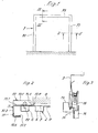
- 1 designates a door frame which is composed of at least two posts 2 and an upper part in the form of a fighter 3.
- the posts 2 consist of a plate-like profile 4 with two U-shaped beads 5, 6 and a plate 7 fastened to the profile 4 and covering the beads 5, 6.
- the posts 2 are at the upper end of the masonry 8 and at the lower end of one threshold not shown attached.
- a first cladding profile 10 partially has a box-like, square shape in cross-section, a first wall 10.1 of the cladding profile 10 extending on the storey side, while a wall 10.2 running at right angles to the first limits the door opening width BT.
- the first wall 10.1 has a z-shaped bend 10.3 forming a flange 10.4.
- a U-profile 11 is fastened to the cladding profile 10 and bears with a longer leg 11.1 on the flange 10.4 and with a shorter leg 11.2 on the inside of a bend 10.5 of the wall 10.2.
- the first cladding profile 10 is fastened to the post 2 by means of screw connections 12, for example.
- the first trim profile 10 is also used as a head piece 13 of the door frame trim (FIG. 3) and, as is not further illustrated and described, is connected to the vertical trim profiles 10 fastened to the posts 2.
- a bore 14 is provided in the head piece 13 for the actuation of an unlocking device 15, by means of which a shaft door 16 can be unlocked in emergencies.
- FIG. 4 shows a second cladding profile 20 den same structure as the first trim profile 10, is however larger than this, for example the walls 20.1, 20.2 are twice as wide as the walls 10.1, 10.2.
- the turn 20.3 is correspondingly wider than the turn 10.3, while the flange 20.4 and the turn 20.5 have the same dimensions.
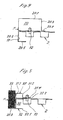
- a third cladding profile 30 a first U-profile 31 with legs 31.1 of unequal length, 31.2, which are bent and form flanges 31.3, 31.4.
- a second U-profile 32 with unequal long legs attached, the shorter leg 32.1 aligned with the flange 31.3, and its longer leg 32.2 abuts flange 31.4.
- the third cladding profile 30 is by means of Screws 12 attached to the post 2.
- a fourth cladding profile with 40 referred to which consists of a first U-profile 41, the one leg 41.1 has a bent flange 41.2, the one with a leg 42.1 of a second U-profile 42 connected is.
- the fourth trim profile is 40 attached to post 2 by means of screw connections 12.
- a hook-shaped Turn 51.2 is provided on one leg 51.1 a hook-shaped Turn 51.2 is provided.
- a second, narrower U-profile 52 with legs of different lengths attached, the shorter leg 52.1 on the Inside of the other leg 51.3 of the first U-profile 51 is present.
- the stiffening plates 53 have a second turn 53.2 on the inner wall of the first U-profile 51 and, for example, by Gluing, attached to this.
- a third turn 53.3 of the stiffening plates 53 is used for attachment to dry masonry, not shown.
- the fifth cladding profile 50 is on the post 2 by means of screw connections 12 attached.
Landscapes
- Elevator Door Apparatuses (AREA)
- Securing Of Glass Panes Or The Like (AREA)
Abstract
Description
In einer bevorzugten Ausführungsform bestehen die Pfosten aus einem plattenartigen Profil mit zwei u-förmigen Sicken und einer am Profil befestigten, die Sicken überdeckenden Platte.
- Fig.1
- eine Ansicht des Türrahmens,
- Fig.2
- einen Querschnitt gemäss der Linie II-II in der Fig.1 in gösserem Massstab, mit einem ersten Verkleidungsprofil,
- Fig.3
- einen Querschnitt gemäss der Linie III-III in der Fig.1 in gegenüber der Fig.2 verkleinertem Massstab,
- Fig.4
- einen Querschnitt wie Fig.2, jedoch mit einem zweiten Verkleidungsprofil,
- Fig.5
- einen Querschnitt wie Fig.2, mit einem dritten Verkleidungsprofil,
- Fig.6
- einen Querschnitt wie Fig.2, mit einem vierten Verkleidungsprofil, und
- Fig.7
- einen Querschnitt wie Fig.2, mit einem fünften Verkleidungsprofil.
Ein erstes Verkleidungsprofil 10 weist im Querschnitt teilweise eine kastenartige, quadratische Form auf, wobei eine erste Wand 10.1 des Verkleidungsprofils 10 stockwerkseitig verläuft, während eine rechtwinklig zur ersten verlaufende Wand 10.2 die Türöffnungsbreite BT begrenzt. Die erste Wand 10.1 hat eine z-förmige, einen Flansch 10.4 bildende Abbiegung 10.3. Am Verkleidungsprofil 10 ist ein U-Profil 11 befestigt, das mit einem längeren Schenkel 11.1 am Flansch 10.4 und mit einem kürzeren Schenkel 11.2 an der Innenseite einer Abbiegung 10.5 der Wand 10.2 anliegt. Das erste Verkleidungsprofil 10 ist beispielsweise mittels Verschraubungen 12 am Pfosten 2 befestigt.
Das erste Verkleidungsprofil 10 wird auch als ein Kopfstück 13 der Türrahmenverkleidung verwendet (Fig.3) und ist, wie nicht weiter dargestellt und beschrieben, mit den senkrecht verlaufenden, an den Pfosten 2 befestigten Verkleidungsprofilen 10 verbunden. Im Kopfstück 13 ist eine Bohrung 14 für die Betätigung einer Entriegelungseinrichtung 15 vorgesehen, mittels welcher in Notfällen eine Schachttür 16 entriegelt werden kann.
Claims (8)
- Türrahmen für Aufzugsschachttüren, wobei der Türrahmendadurch gekennzeichnet, dass die Pfosten (2) mit Verkleidungsprofilen (10,20,30, 40,50) verschiedener Form und Grösse kombinierbar sind.(1) mindestens aus zwei Pfosten (2) und einem Oberteil(3) zusammengesetzt ist,
- Türrahmen nach Anspruch 1,
dadurch gekennzeichnet, dass die Pfosten (2) aus einem plattenartigen Profil (4) mit zwei u-förmigen Sicken (5,6) und einer am Profil (4) befestigten, die Sicken (5,6) überdeckenden Platte (7) bestehen. - Türrahmen nach Anspruch 1,
dadurch gekennzeichnet,dass ein erstes Verkleidungsprofil (10) im Querschnitt teilweise eine kastenartige, quadratische Form aufweist, wobei eine erste Wand (10.1) des Verkleidungsprofiles (10) stockwerkseitig verläuft, während eine rechtwinklig zur ersten verlaufende Wand (10.2) eine Türöffnungsbreite (BT) begrenzt,dass die erste Wand (10.1) eine z-förmige, einen Flansch (10.4) bildende Abbiegung (10.3) aufweist, unddass am Verkleidungsprofil (10) ein U-Profil (11) befestigt ist, das mit einem längeren Schenkel (11.1) am Flansch (10.4) und mit einem kürzeren Schenkel (11.2) an der Innenseite einer Abbiegung (10.5) der Wand (10.2) anliegt. - Türrahmen hach Anspruch 1,
dadurch gekennzeichnet,dass ein drittes Verkleidungsprofil (30) aus einem ersten U-Profil (31) mit ungleich langen Schenkeln (31.1, 31.2) besteht, die abgebogen sind und Flansche (31.3, 31.4) bilden,dass am ersten U-Profil (31) ein zweites U-Profil (32) mit ungleich langen Schenkeln befestigt ist, dessen kürzerer Schenkel (32.1) mit dem Fansch (31.3) fluchtet, und dessen längerer Schenkel (32.2) am Flansch (31.4) anliegt, unddass durch den Schenkel (31.1) und den Flansch (31.3) Anlageflächen für ein weiteres Verkleidungselement (33) gebildet werden. - Türrahmen nach Anspruch 1,
dadurch gekennzeichnet, dass ein viertes Verkleidungsprofil (40) aus einem ersten U-Profil (41) besteht, dessen einer Schenkel (41.1) einen angebogenen Flansch (41.2) aufweist, der mit einem Schenkel (42.1) eines zweiten U-Profiles (42) verbunden ist, wobei durch den Schenkel (41.1) und den Flansch (41.2) des ersten U-Profiles (41) Anlageflächen für ein weiteres Verkleidungselement (43) gebildet werden. - Türrahmen nach Anspruch 1,
dadurch gekennzeichnet.dass ein fünftes Verkleidungsprofil (50) aus einem ersten U-Profil (51) besteht, an dessem einen Schenkel (51.1) eine hakenförmige Abbiegung (51.2) vorgesehen ist,dass am ersten U-Profil (51) ein zweites U-Profil (52) mit ungleich langen Schenkeln befestigt ist, dessen küzerer Schenkel (52.1) an der Innenseite des anderen Schenkels (51.3) des ersten U-Profiles (51) anliegt,dass im ersten U-Profil (51) Versteifungsplatten (53) angeordnet sind, die an einem Ende in die hakenförmige Abbiegung (51.2) eingreifen und am anderen Ende mit einer Abbiegung (53.1) auf dem längeren Schenkel (52.2) des zweiten U-Profiles (52) aufliegen, unddass die Versteifungsplatten (53) eine zweite Abbiegung (53.2) für die Befestigung am ersten U-Profil (51) aufweisen. - Türrahmen nach Anspruch 6,
dadurch gekennzeichnet, dass die Versteifungsplatten (53) durch Verklebung am ersten U-Profil (51) befestigt sind. - Türrahmen nach Anspruch 1,
dadurch gekennzeichnet, dass die Verkleidungsprofile (10,20,30,40,50) mittels Verschraubungen (12) an den Pfosten (2) befestigt sind.
Priority Applications (1)
| Application Number | Priority Date | Filing Date | Title |
|---|---|---|---|
| EP20020009918 EP1258446B1 (de) | 2001-05-14 | 2002-05-03 | Türrahmen für Aufzugsschachttüren |
Applications Claiming Priority (3)
| Application Number | Priority Date | Filing Date | Title |
|---|---|---|---|
| EP01810473 | 2001-05-14 | ||
| EP01810473 | 2001-05-14 | ||
| EP20020009918 EP1258446B1 (de) | 2001-05-14 | 2002-05-03 | Türrahmen für Aufzugsschachttüren |
Publications (2)
| Publication Number | Publication Date |
|---|---|
| EP1258446A1 true EP1258446A1 (de) | 2002-11-20 |
| EP1258446B1 EP1258446B1 (de) | 2010-12-22 |
Family
ID=26077376
Family Applications (1)
| Application Number | Title | Priority Date | Filing Date |
|---|---|---|---|
| EP20020009918 Expired - Lifetime EP1258446B1 (de) | 2001-05-14 | 2002-05-03 | Türrahmen für Aufzugsschachttüren |
Country Status (1)
| Country | Link |
|---|---|
| EP (1) | EP1258446B1 (de) |
Cited By (1)
| Publication number | Priority date | Publication date | Assignee | Title |
|---|---|---|---|---|
| EP1655439A3 (de) * | 2004-11-03 | 2007-01-17 | Novoferm GmbH | Türzarge, insbesondere für Fahrschachttüren |
Citations (4)
| Publication number | Priority date | Publication date | Assignee | Title |
|---|---|---|---|---|
| DE2245156A1 (de) * | 1972-09-14 | 1974-03-21 | Fiand F Gmbh | Anordnung eines zargenankers an einer stahlzarge |
| EP0534789A1 (de) * | 1991-09-25 | 1993-03-31 | Otis Elevator Company | Universelle Türzarge |
| EP0621224A2 (de) * | 1993-04-23 | 1994-10-26 | Kone Oy | System zum Einrichten der Schachttüreinfassung eines Aufzugs |
| JPH11335011A (ja) * | 1998-05-26 | 1999-12-07 | Matsushita Electric Works Ltd | エレベータの制御盤の組込み構造 |
-
2002
- 2002-05-03 EP EP20020009918 patent/EP1258446B1/de not_active Expired - Lifetime
Patent Citations (4)
| Publication number | Priority date | Publication date | Assignee | Title |
|---|---|---|---|---|
| DE2245156A1 (de) * | 1972-09-14 | 1974-03-21 | Fiand F Gmbh | Anordnung eines zargenankers an einer stahlzarge |
| EP0534789A1 (de) * | 1991-09-25 | 1993-03-31 | Otis Elevator Company | Universelle Türzarge |
| EP0621224A2 (de) * | 1993-04-23 | 1994-10-26 | Kone Oy | System zum Einrichten der Schachttüreinfassung eines Aufzugs |
| JPH11335011A (ja) * | 1998-05-26 | 1999-12-07 | Matsushita Electric Works Ltd | エレベータの制御盤の組込み構造 |
Non-Patent Citations (1)
| Title |
|---|
| PATENT ABSTRACTS OF JAPAN vol. 2000, no. 03 30 March 2000 (2000-03-30) * |
Cited By (1)
| Publication number | Priority date | Publication date | Assignee | Title |
|---|---|---|---|---|
| EP1655439A3 (de) * | 2004-11-03 | 2007-01-17 | Novoferm GmbH | Türzarge, insbesondere für Fahrschachttüren |
Also Published As
| Publication number | Publication date |
|---|---|
| EP1258446B1 (de) | 2010-12-22 |
Similar Documents
| Publication | Publication Date | Title |
|---|---|---|
| DE4133720C2 (de) | Feststell- und Verriegelungseinheit | |
| DE69433291T2 (de) | Profilsatz zur Herstellung von durchgehenden Fassaden für Zivilgebäude oder dergleichen | |
| DE2756337C3 (de) | Bauelementensatz zur Herstellung von selbst-tragenden Gebäuden aus vorgefertigten Beton-Bauelementen | |
| EP1258446B1 (de) | Türrahmen für Aufzugsschachttüren | |
| DE9406592U1 (de) | Hochlochziegel | |
| DE69407799T2 (de) | Verfahren zum herstellen einer holzkonstruktion und holzkonstruktion | |
| DE631778C (de) | Loesbare Verbindung von Bauteilen fuer Spiel- und Lehrzwecke | |
| DE3424173C1 (de) | Vorgefertigtes Bauelement aus Glashohlbausteinen | |
| DE2835054A1 (de) | Abdichtung fuer eine dehnungsfuge in einem fussboden | |
| DE3702298C2 (de) | ||
| DE7716996U1 (de) | Profilstabaggregat | |
| DE102019116533B4 (de) | Deckenanordnung | |
| CH674662A5 (en) | Profiled door frame member - has one side extended to form door stop and transverse groove at middle | |
| DE9001552U1 (de) | Plattenförmiges Bauelement | |
| DE3909803A1 (de) | Industriefussboden aus miteinander verriegelten rechteckigen betonplatten | |
| DE1943108U (de) | Vorgefertigte treppe. | |
| DE2123156A1 (de) | Fassade aus Fertigteilen | |
| DE19836171B4 (de) | Fertigteilsatz zur Errichtung eines Gebäudes | |
| DE9115330U1 (de) | Kupplung für Profile für abgehängte Decken und dazu angewandte Profile | |
| DE8915474U1 (de) | Rahmenverbindung zwischen Rahmenelementen eines Holzbauwerkes, insbesondere von Wintergärten, Carports, Pergolen o.dgl. | |
| DE1805979C (de) | Verkleidungsplatte aus Asbestzement für Wände od. dgl | |
| DE2541040B2 (de) | Schaukasten | |
| EP1589158A2 (de) | Vorrichtung zur Befestigung von Fassadenelementen | |
| DE9316247U1 (de) | Balkongeländer | |
| DE69906010T2 (de) | Tonfliese zum Erstellen von Trennwänden |
Legal Events
| Date | Code | Title | Description |
|---|---|---|---|
| PUAI | Public reference made under article 153(3) epc to a published international application that has entered the european phase |
Free format text: ORIGINAL CODE: 0009012 |
|
| AK | Designated contracting states |
Kind code of ref document: A1 Designated state(s): AT BE CH CY DE DK ES FI FR GB GR IE IT LI LU MC NL PT SE TR |
|
| AX | Request for extension of the european patent |
Free format text: AL;LT;LV;MK;RO;SI |
|
| 17P | Request for examination filed |
Effective date: 20030428 |
|
| AKX | Designation fees paid |
Designated state(s): AT BE CH CY DE DK ES FI FR GB GR IE IT LI LU MC NL PT SE TR |
|
| 17Q | First examination report despatched |
Effective date: 20090306 |
|
| GRAP | Despatch of communication of intention to grant a patent |
Free format text: ORIGINAL CODE: EPIDOSNIGR1 |
|
| GRAS | Grant fee paid |
Free format text: ORIGINAL CODE: EPIDOSNIGR3 |
|
| GRAA | (expected) grant |
Free format text: ORIGINAL CODE: 0009210 |
|
| AK | Designated contracting states |
Kind code of ref document: B1 Designated state(s): AT BE CH CY DE DK ES FI FR GB GR IE IT LI LU MC NL PT SE TR |
|
| REG | Reference to a national code |
Ref country code: GB Ref legal event code: FG4D Free format text: NOT ENGLISH |
|
| REG | Reference to a national code |
Ref country code: CH Ref legal event code: EP |
|
| REG | Reference to a national code |
Ref country code: IE Ref legal event code: FG4D |
|
| REF | Corresponds to: |
Ref document number: 50214820 Country of ref document: DE Date of ref document: 20110203 Kind code of ref document: P |
|
| REG | Reference to a national code |
Ref country code: DE Ref legal event code: R096 Ref document number: 50214820 Country of ref document: DE Effective date: 20110203 |
|
| REG | Reference to a national code |
Ref country code: NL Ref legal event code: VDEP Effective date: 20101222 |
|
| PG25 | Lapsed in a contracting state [announced via postgrant information from national office to epo] |
Ref country code: SE Free format text: LAPSE BECAUSE OF FAILURE TO SUBMIT A TRANSLATION OF THE DESCRIPTION OR TO PAY THE FEE WITHIN THE PRESCRIBED TIME-LIMIT Effective date: 20101222 Ref country code: CY Free format text: LAPSE BECAUSE OF FAILURE TO SUBMIT A TRANSLATION OF THE DESCRIPTION OR TO PAY THE FEE WITHIN THE PRESCRIBED TIME-LIMIT Effective date: 20101222 Ref country code: FI Free format text: LAPSE BECAUSE OF FAILURE TO SUBMIT A TRANSLATION OF THE DESCRIPTION OR TO PAY THE FEE WITHIN THE PRESCRIBED TIME-LIMIT Effective date: 20101222 |
|
| REG | Reference to a national code |
Ref country code: IE Ref legal event code: FD4D |
|
| PG25 | Lapsed in a contracting state [announced via postgrant information from national office to epo] |
Ref country code: GR Free format text: LAPSE BECAUSE OF FAILURE TO SUBMIT A TRANSLATION OF THE DESCRIPTION OR TO PAY THE FEE WITHIN THE PRESCRIBED TIME-LIMIT Effective date: 20110323 Ref country code: ES Free format text: LAPSE BECAUSE OF FAILURE TO SUBMIT A TRANSLATION OF THE DESCRIPTION OR TO PAY THE FEE WITHIN THE PRESCRIBED TIME-LIMIT Effective date: 20110402 Ref country code: PT Free format text: LAPSE BECAUSE OF FAILURE TO SUBMIT A TRANSLATION OF THE DESCRIPTION OR TO PAY THE FEE WITHIN THE PRESCRIBED TIME-LIMIT Effective date: 20110422 |
|
| REG | Reference to a national code |
Ref country code: HK Ref legal event code: GR Ref document number: 1051522 Country of ref document: HK |
|
| PG25 | Lapsed in a contracting state [announced via postgrant information from national office to epo] |
Ref country code: NL Free format text: LAPSE BECAUSE OF FAILURE TO SUBMIT A TRANSLATION OF THE DESCRIPTION OR TO PAY THE FEE WITHIN THE PRESCRIBED TIME-LIMIT Effective date: 20101222 |
|
| PLBE | No opposition filed within time limit |
Free format text: ORIGINAL CODE: 0009261 |
|
| STAA | Information on the status of an ep patent application or granted ep patent |
Free format text: STATUS: NO OPPOSITION FILED WITHIN TIME LIMIT |
|
| PG25 | Lapsed in a contracting state [announced via postgrant information from national office to epo] |
Ref country code: IE Free format text: LAPSE BECAUSE OF FAILURE TO SUBMIT A TRANSLATION OF THE DESCRIPTION OR TO PAY THE FEE WITHIN THE PRESCRIBED TIME-LIMIT Effective date: 20101222 Ref country code: DK Free format text: LAPSE BECAUSE OF FAILURE TO SUBMIT A TRANSLATION OF THE DESCRIPTION OR TO PAY THE FEE WITHIN THE PRESCRIBED TIME-LIMIT Effective date: 20101222 |
|
| 26N | No opposition filed |
Effective date: 20110923 |
|
| BERE | Be: lapsed |
Owner name: INVENTIO A.G. Effective date: 20110531 |
|
| PG25 | Lapsed in a contracting state [announced via postgrant information from national office to epo] |
Ref country code: IT Free format text: LAPSE BECAUSE OF FAILURE TO SUBMIT A TRANSLATION OF THE DESCRIPTION OR TO PAY THE FEE WITHIN THE PRESCRIBED TIME-LIMIT Effective date: 20101222 Ref country code: MC Free format text: LAPSE BECAUSE OF NON-PAYMENT OF DUE FEES Effective date: 20110531 |
|
| REG | Reference to a national code |
Ref country code: CH Ref legal event code: PL |
|
| REG | Reference to a national code |
Ref country code: DE Ref legal event code: R097 Ref document number: 50214820 Country of ref document: DE Effective date: 20110923 |
|
| PG25 | Lapsed in a contracting state [announced via postgrant information from national office to epo] |
Ref country code: CH Free format text: LAPSE BECAUSE OF NON-PAYMENT OF DUE FEES Effective date: 20110531 Ref country code: LI Free format text: LAPSE BECAUSE OF NON-PAYMENT OF DUE FEES Effective date: 20110531 |
|
| PG25 | Lapsed in a contracting state [announced via postgrant information from national office to epo] |
Ref country code: BE Free format text: LAPSE BECAUSE OF NON-PAYMENT OF DUE FEES Effective date: 20110531 |
|
| REG | Reference to a national code |
Ref country code: AT Ref legal event code: MM01 Ref document number: 492503 Country of ref document: AT Kind code of ref document: T Effective date: 20110503 |
|
| PG25 | Lapsed in a contracting state [announced via postgrant information from national office to epo] |
Ref country code: AT Free format text: LAPSE BECAUSE OF NON-PAYMENT OF DUE FEES Effective date: 20110503 |
|
| PG25 | Lapsed in a contracting state [announced via postgrant information from national office to epo] |
Ref country code: LU Free format text: LAPSE BECAUSE OF NON-PAYMENT OF DUE FEES Effective date: 20110503 |
|
| PG25 | Lapsed in a contracting state [announced via postgrant information from national office to epo] |
Ref country code: TR Free format text: LAPSE BECAUSE OF FAILURE TO SUBMIT A TRANSLATION OF THE DESCRIPTION OR TO PAY THE FEE WITHIN THE PRESCRIBED TIME-LIMIT Effective date: 20101222 |
|
| REG | Reference to a national code |
Ref country code: FR Ref legal event code: PLFP Year of fee payment: 14 |
|
| PGFP | Annual fee paid to national office [announced via postgrant information from national office to epo] |
Ref country code: GB Payment date: 20150521 Year of fee payment: 14 Ref country code: DE Payment date: 20150521 Year of fee payment: 14 |
|
| PGFP | Annual fee paid to national office [announced via postgrant information from national office to epo] |
Ref country code: FR Payment date: 20150521 Year of fee payment: 14 |
|
| REG | Reference to a national code |
Ref country code: DE Ref legal event code: R119 Ref document number: 50214820 Country of ref document: DE |
|
| GBPC | Gb: european patent ceased through non-payment of renewal fee |
Effective date: 20160503 |
|
| REG | Reference to a national code |
Ref country code: FR Ref legal event code: ST Effective date: 20170131 |
|
| PG25 | Lapsed in a contracting state [announced via postgrant information from national office to epo] |
Ref country code: DE Free format text: LAPSE BECAUSE OF NON-PAYMENT OF DUE FEES Effective date: 20161201 Ref country code: FR Free format text: LAPSE BECAUSE OF NON-PAYMENT OF DUE FEES Effective date: 20160531 |
|
| PG25 | Lapsed in a contracting state [announced via postgrant information from national office to epo] |
Ref country code: GB Free format text: LAPSE BECAUSE OF NON-PAYMENT OF DUE FEES Effective date: 20160503 |