EP1256293A2 - Stuhl, insbesondere Bürostuhl - Google Patents
Stuhl, insbesondere Bürostuhl Download PDFInfo
- Publication number
- EP1256293A2 EP1256293A2 EP02010377A EP02010377A EP1256293A2 EP 1256293 A2 EP1256293 A2 EP 1256293A2 EP 02010377 A EP02010377 A EP 02010377A EP 02010377 A EP02010377 A EP 02010377A EP 1256293 A2 EP1256293 A2 EP 1256293A2
- Authority
- EP
- European Patent Office
- Prior art keywords
- seat
- backrest
- support
- chair
- link
- Prior art date
- Legal status (The legal status is an assumption and is not a legal conclusion. Google has not performed a legal analysis and makes no representation as to the accuracy of the status listed.)
- Granted
Links
- 230000007246 mechanism Effects 0.000 description 5
- 230000001360 synchronised effect Effects 0.000 description 4
- 238000010276 construction Methods 0.000 description 2
- 230000008878 coupling Effects 0.000 description 2
- 238000010168 coupling process Methods 0.000 description 2
- 238000005859 coupling reaction Methods 0.000 description 2
- 238000006073 displacement reaction Methods 0.000 description 1
- 230000002996 emotional effect Effects 0.000 description 1
Images
Classifications
-
- A—HUMAN NECESSITIES
- A47—FURNITURE; DOMESTIC ARTICLES OR APPLIANCES; COFFEE MILLS; SPICE MILLS; SUCTION CLEANERS IN GENERAL
- A47C—CHAIRS; SOFAS; BEDS
- A47C1/00—Chairs adapted for special purposes
- A47C1/02—Reclining or easy chairs
- A47C1/031—Reclining or easy chairs having coupled concurrently adjustable supporting parts
- A47C1/032—Reclining or easy chairs having coupled concurrently adjustable supporting parts the parts being movably-coupled seat and back-rest
- A47C1/03255—Reclining or easy chairs having coupled concurrently adjustable supporting parts the parts being movably-coupled seat and back-rest with a central column, e.g. rocking office chairs
-
- A—HUMAN NECESSITIES
- A47—FURNITURE; DOMESTIC ARTICLES OR APPLIANCES; COFFEE MILLS; SPICE MILLS; SUCTION CLEANERS IN GENERAL
- A47C—CHAIRS; SOFAS; BEDS
- A47C1/00—Chairs adapted for special purposes
- A47C1/02—Reclining or easy chairs
- A47C1/031—Reclining or easy chairs having coupled concurrently adjustable supporting parts
- A47C1/032—Reclining or easy chairs having coupled concurrently adjustable supporting parts the parts being movably-coupled seat and back-rest
- A47C1/03294—Reclining or easy chairs having coupled concurrently adjustable supporting parts the parts being movably-coupled seat and back-rest slidingly movable in the base frame, e.g. by rollers
Definitions
- the invention relates to a chair, in particular office chair, with an over a backrest carrier articulated on a backrest and with one synchronously movable seat, the front area via a sliding guide and the rear area via a seat link with the seat support connected is.
- the synchronous mechanism serves to adjust the backrest change the position of the seat at the same time.
- the invention is therefore based on the object of a chair, in particular a chair Office chair, with a particularly suitable and easy-to-implement synchronizing mechanism specify.
- the invention is based on the consideration that with a chair or Seating with adjustable seat and adjustable backrest the adjustment options from the seat on the one hand and the backrest on the other can be viewed independently.
- the construction thus points initially two degrees of freedom.
- the backrest can be adjusted only a single degree of freedom when the articulation of the backrest on the seat support in a simple manner via the rigid with the backrest connected backrest support is realized on the seat support via a single Rotational axis is rotatably attached.
- the seat can be more complex Have adjustment options, being analogous to the adjustability of the backrest nevertheless it can be assumed that the setting options the seat can be written with a single degree of freedom.
- the movement can do both a translation and a tilting movement or a combination of different forms of movement.
- the seat surface can be moved in a rigid axis connected to it be provided in the elongated hole provided in the backrest link. It is advantageous however, the upper pivot point common to the seat surface and the seat link in a corresponding slot in the backrest handlebar.
- the seat handlebar is included expediently concave in the direction of the seat.
- the sliding guide provided in the front seating area can be adjusted in the seat support provided slot and one guided therein, rigid with the seat connected axis or be realized by a cylinder. Regardless of that advantageously an obliquely downward in the direction of the seat support Sliding guide provided. Due to the inclined arrangement of the length compensation element effective front sliding guide of the seat not just an undesirable lifting of the front edge of the seat when leaning back avoided the backrest, but rather a lowering of the The front edge of the seat is reached when the backrest is tilted back. This Lowering is more pronounced, the more the inclination of the sliding guide deviates from the horizontal and runs towards the vertical.
- the seat link connected to the seat outward inclination of the seat handlebars forward and down becomes more ergonomic
- the seat increases when you lean back the backrest mainly lowers in its rear area, while at the same time the front edge of the seat back and forth moved down. This gives the seat in the desired manner in its rear area a greater range of motion than in the front Area.
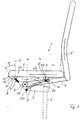
- the chair 1 designed as an office chair according to FIG. 1 comprises a fixed one Dashed base 2 connected seat support 3. With the seat support 3, a backrest 5 is rotatably connected via a backrest support 4. The Backrest 5 is out of the rest position shown in FIG. 1 the reclined position or position shown in Fig. 2 tiltable backwards. The inclination of the backrest 5 is done by a rotation of one Pivot D1.
- the backrest support is firmly connected to the backrest 5 4 connected to the seat support 3 via an axis of rotation A, the fulcrum D1 is essentially given by the central axis of this axis of rotation A.
- a seat surface 6 is also articulated on the seat support 3 via a seat link 7, which in the exemplary embodiment is convex in the direction of the seat 6 or is curved.
- the seat link 7 is with the seat support 3 via a swivel joint D2 and with the seat 6 in its rear area, i.e. in the backrest 5 facing rear seat half 6b rotatable via a swivel joint D3 connected.
- the pivot points D2 and D3 are in turn by corresponding ones Realized axes of rotation via which the seat link 7 with the seat support 3 on the one hand and is rotatably connected to the seat 6 on the other hand.
- the seat surface 6 is connected to the seat support 3 via a sliding guide 8.
- the sliding guide 8 can be designed in a manner not shown in the form of an elongated hole in the seat support 3 and a rigid axis 9 guided therein and connected to the seat surface 6 or — as shown — as a cylinder guided in the seat support 3. This is then rotatably connected to the seat 6 via the axis 9.
- the sliding guide 8 is inclined in the direction of the base 2.
- the backrest 5 is tilted backwards into that shown in Fig. 2 Positioned, the backrest support 4 is clockwise by this inclination rotated and thus the seat link 7 together with the seat 6 down emotional.
- the angle ⁇ between the seat link 7 and the vertical increases V from about 45 ° to 60 ° to about 90 °.
- the seat handlebar is in the end position 7 almost horizontal.
- the seat link 7 lies with the seat surface 6 connecting upper pivot D3 based on the seat 6 lower than that the backrest support 4 with the seat support 3 connecting pivot D1, while this is in the rest position below the pivot point D3.
Landscapes
- Health & Medical Sciences (AREA)
- Dentistry (AREA)
- General Health & Medical Sciences (AREA)
- Chairs For Special Purposes, Such As Reclining Chairs (AREA)
- Chairs Characterized By Structure (AREA)
- Hydrogenated Pyridines (AREA)
Abstract
Description
- Fig. 1
- in schematischer Seitenansicht einen Bürostuhl in Ruheposition,
- Fig. 2
- den Bürostuhl gemäß Fig. 1 in nach hinten zurückgeneigter Endstellung.
- 1
- Stuhl
- 2
- Standfuß
- 3
- Sitzträger
- 4
- Lehnenträger
- 5
- Rückenlehne
- 6
- Sitzfläche
- 6a
- vordere Sitzhälfte
- 6b
- hintere Sitzhälfte
- 7
- Sitzträger
- 8
- Schiebeführung
- 9
- Achse
- 10
- Schiebeführung
- 11
- Langloch
- 12
- Achse
- 13
- Sitzvorderkante
- 14
- Pfeil
- A
- Drehachse
- a,b
- Abstand
- α,β
- Neigungswinkel
- D1 bis D3
- Drehpunkt
- V
- Vertikale
Claims (5)
- Stuhl, insbesondere Bürostuhl, mit einer über einen Lehnenträger (4) an einem Sitzträger (3) angelenkten Rückenlehne (5) und mit einer synchron hierzu bewegbaren Sitzfläche (6), deren vorderer Bereich (6a) über eine Schiebeführung (8) und deren hinterer Bereich (6b) über einen Sitzlenker (7) mit dem Sitzträger (3) verbunden ist,
dadurch gekennzeichnet, dass der Abstand (a) des den Sitzlenker (7) mit der Sitzfläche (6) verbindenden oberen Drehpunktes (D3) zur Rückenlehne (5) kleiner ist als der Abstand (b) des den Sitzlenker (7) mit dem Sitzträger (3) verbindenden unteren Drehpunktes (D2) zur Rückenlehne (5), und dass zur Synchronisation zwischen der Bewegung der Rückenlehne (5) und der Bewegung der Sitzfläche (6) eine Schiebeführung (10) der Sitzfläche (6) im Lehnenträger (4) vorgesehen ist. - Stuhl nach Anspruch 1,
dadurch gekennzeichnet, dass der obere Drehpunkt (D3) in einem im Lehnenträger (4) vorgesehenen Langloch (11) geführt ist. - Stuhl nach Anspruch 1 oder 2,
dadurch gekennzeichnet, dass im vorderen Bereich (6a) der Sitzfläche (6) eine in Richtung auf den Sitzträger (3) schräg nach unten verlaufende Schiebeführung (8) vorgesehen ist. - Stuhl nach einem der Ansprüche 1 bis 3,
dadurch gekennzeichnet, dass der Sitzlenker (7) in Richtung zur Sitzfläche (6) konkav gewölbt ist. - Stuhl nach einem der Ansprüche 1 bis 4,
dadurch gekennzeichnet, dass in nach hinten zurückgeneigter Stellung der Rückenlehne (5) der den Sitzlenker (7) mit der Sitzfläche (6) verbindende obere Drehpunkt (D3) bezogen auf die Sitzfläche (6) tiefer liegt als ein den Lehnenträger (4) mit dem Sitzträger (3) verbindender Drehpunkt (D1).
Applications Claiming Priority (2)
| Application Number | Priority Date | Filing Date | Title |
|---|---|---|---|
| DE10122946A DE10122946C1 (de) | 2001-05-11 | 2001-05-11 | Stuhl, insbesondere Bürostuhl |
| DE10122946 | 2001-05-11 |
Publications (3)
| Publication Number | Publication Date |
|---|---|
| EP1256293A2 true EP1256293A2 (de) | 2002-11-13 |
| EP1256293A3 EP1256293A3 (de) | 2003-11-26 |
| EP1256293B1 EP1256293B1 (de) | 2007-01-03 |
Family
ID=7684422
Family Applications (1)
| Application Number | Title | Priority Date | Filing Date |
|---|---|---|---|
| EP02010377A Expired - Lifetime EP1256293B1 (de) | 2001-05-11 | 2002-05-08 | Stuhl, insbesondere Bürostuhl |
Country Status (4)
| Country | Link |
|---|---|
| US (1) | US6692075B2 (de) |
| EP (1) | EP1256293B1 (de) |
| AT (1) | ATE349934T1 (de) |
| DE (2) | DE10122946C1 (de) |
Cited By (2)
| Publication number | Priority date | Publication date | Assignee | Title |
|---|---|---|---|---|
| DE102006023981A1 (de) * | 2006-05-22 | 2007-12-06 | Wilkhahn Wilkening + Hahne Gmbh & Co. Kg | Stuhl |
| EP2792275A1 (de) | 2013-04-18 | 2014-10-22 | Thergofit GmbH | Lehnstuhl |
Families Citing this family (21)
| Publication number | Priority date | Publication date | Assignee | Title |
|---|---|---|---|---|
| WO2002032262A1 (en) * | 2000-10-16 | 2002-04-25 | Kokuyo Co., Ltd. | Chair |
| NO317791B1 (no) * | 2002-01-04 | 2004-12-13 | Stokke As | Bevegelig ledd |
| DE10318759B3 (de) | 2003-04-25 | 2004-07-29 | Armin Sander | Stuhl, insbesondere Bürostuhl, und modulares Stuhlkonzept |
| US20090015050A1 (en) * | 2004-03-13 | 2009-01-15 | Hans Dehli | Articulating chair |
| DE202005004880U1 (de) | 2005-03-26 | 2006-08-03 | Sander, Armin | Stuhl, insbesondere Bürostuhl |
| US7261368B1 (en) * | 2006-02-27 | 2007-08-28 | Todd Clausnitzer | Ergonomic chair |
| CN101431923B (zh) * | 2006-04-24 | 2012-03-28 | 休思乐公司 | 具有自动调节抗倾斜性能的椅子 |
| EP1908374B1 (de) * | 2006-10-06 | 2009-02-11 | Stoll Giroflex AG | Synchron-Bürostuhl |
| WO2011124027A1 (zh) * | 2010-04-07 | 2011-10-13 | Lin Jingheng | 具有自由滑滚联动机构的座椅家具 |
| EP2630894A4 (de) * | 2010-10-19 | 2014-11-12 | Okamura Corp | Stuhl mit armlehne |
| DE102011104972B4 (de) | 2011-06-08 | 2015-03-05 | Haworth, Inc. | Sitzmöbel, insbesondere Bürostuhl |
| US9504326B1 (en) | 2012-04-10 | 2016-11-29 | Humanscale Corporation | Reclining chair |
| US9706845B2 (en) | 2012-09-20 | 2017-07-18 | Steelcase Inc. | Chair assembly |
| WO2015161281A1 (en) | 2014-04-17 | 2015-10-22 | Hni Technologies Inc. | Chair and chair control assemblies, systems, and methods |
| CN120531243A (zh) | 2015-04-13 | 2025-08-26 | 斯迪尔科斯公司 | 座位布置 |
| US10194750B2 (en) | 2015-04-13 | 2019-02-05 | Steelcase Inc. | Seating arrangement |
| US11259637B2 (en) | 2015-04-13 | 2022-03-01 | Steelcase Inc. | Seating arrangement |
| US10966527B2 (en) | 2017-06-09 | 2021-04-06 | Steelcase Inc. | Seating arrangement and method of construction |
| DE202017100480U1 (de) | 2017-01-30 | 2018-05-03 | Armin Sander | Sitzmöbel, insbesondere Bürostuhl |
| AU2020224628B2 (en) | 2019-02-21 | 2025-04-24 | Steelcase Inc. | Body support assembly and methods for the use and assembly thereof |
| US11357329B2 (en) | 2019-12-13 | 2022-06-14 | Steelcase Inc. | Body support assembly and methods for the use and assembly thereof |
Citations (1)
| Publication number | Priority date | Publication date | Assignee | Title |
|---|---|---|---|---|
| DE4219599A1 (de) | 1992-06-16 | 1993-12-23 | Sdm Hansen Ag St Margrethen | Synchronverstelleinrichtung für Bürostühle oder dergleichen |
Family Cites Families (15)
| Publication number | Priority date | Publication date | Assignee | Title |
|---|---|---|---|---|
| CA806983A (en) * | 1965-07-23 | 1969-02-25 | Dufton Ronald | Chair tilting mechanism |
| ATE27763T1 (de) * | 1983-10-05 | 1987-07-15 | Giroflex Entwicklungs Ag | Stuhl mit neigbarem sitz- und lehnenteil. |
| DE3642796A1 (de) * | 1986-12-15 | 1988-06-23 | Eckhard Hansen | Punktsynchronverstelleinrichtung fuer buerostuehle, sitzmoebel o. dgl. |
| US4854641A (en) * | 1989-01-23 | 1989-08-08 | Reineman Richard G | Adjustable chair |
| DE3916474A1 (de) * | 1989-05-20 | 1990-11-22 | Roeder Soehne Sitzmoebelfab | Stuhl, insbesondere arbeits- oder buerostuhl |
| US5288138A (en) * | 1990-08-10 | 1994-02-22 | Stulik Edward L | Reclining chair |
| DE4038059A1 (de) * | 1990-11-29 | 1992-06-04 | Bock Martin Kunststoff | Sitztraeger fuer einen buerostuhl o. dgl. |
| DE4135948C2 (de) * | 1991-10-31 | 1993-12-23 | Rolf Voelkle | Stuhl, insbesondere Bürodrehstuhl |
| IL103477A0 (en) * | 1992-10-20 | 1993-03-15 | Paltechnica Nitzanim | Office and like chairs |
| DE4312113C1 (de) * | 1993-04-14 | 1994-10-27 | Mauser Waldeck Ag | Sitzmöbel |
| EP0726723B1 (de) * | 1993-11-01 | 1998-11-25 | Labofa A/S | Bürostuhl mit synchroner verstellung von sitz und rückenlehne |
| US5826940A (en) * | 1995-11-27 | 1998-10-27 | Hodgdon; Dewey | Reactive multi-position chair |
| DE19702328A1 (de) * | 1997-01-23 | 1998-07-30 | Comforto Gmbh | Stuhl mit Synchronmechanik |
| DE19726160A1 (de) * | 1997-06-20 | 1998-12-24 | Johannes Uhlenbrock | Sitzmöbel, insbesondere Bürodrehstuhl |
| WO2000022959A1 (de) * | 1998-10-20 | 2000-04-27 | Protoned B.V. | Stuhlmechanik |
-
2001
- 2001-05-11 DE DE10122946A patent/DE10122946C1/de not_active Expired - Fee Related
- 2001-09-25 US US09/963,008 patent/US6692075B2/en not_active Expired - Fee Related
-
2002
- 2002-05-08 AT AT02010377T patent/ATE349934T1/de not_active IP Right Cessation
- 2002-05-08 EP EP02010377A patent/EP1256293B1/de not_active Expired - Lifetime
- 2002-05-08 DE DE50209126T patent/DE50209126D1/de not_active Expired - Fee Related
Patent Citations (1)
| Publication number | Priority date | Publication date | Assignee | Title |
|---|---|---|---|---|
| DE4219599A1 (de) | 1992-06-16 | 1993-12-23 | Sdm Hansen Ag St Margrethen | Synchronverstelleinrichtung für Bürostühle oder dergleichen |
Cited By (4)
| Publication number | Priority date | Publication date | Assignee | Title |
|---|---|---|---|---|
| DE102006023981A1 (de) * | 2006-05-22 | 2007-12-06 | Wilkhahn Wilkening + Hahne Gmbh & Co. Kg | Stuhl |
| US7770973B2 (en) | 2006-05-22 | 2010-08-10 | Wilkhahn Wilkening + Hahne Gmbh + Co. Kg | Chair |
| EP2792275A1 (de) | 2013-04-18 | 2014-10-22 | Thergofit GmbH | Lehnstuhl |
| CH707927A1 (de) * | 2013-04-18 | 2014-10-31 | Thergofit Gmbh | Lehnstuhl. |
Also Published As
| Publication number | Publication date |
|---|---|
| US20020167208A1 (en) | 2002-11-14 |
| EP1256293A3 (de) | 2003-11-26 |
| US6692075B2 (en) | 2004-02-17 |
| DE50209126D1 (de) | 2007-02-15 |
| DE10122946C1 (de) | 2003-01-30 |
| EP1256293B1 (de) | 2007-01-03 |
| ATE349934T1 (de) | 2007-01-15 |
Similar Documents
| Publication | Publication Date | Title |
|---|---|---|
| DE10122948C1 (de) | Stuhl, insbesondere Bürostuhl | |
| DE10122946C1 (de) | Stuhl, insbesondere Bürostuhl | |
| EP1256294B1 (de) | Stuhl, insbesondere Bürostuhl | |
| DE10026475A1 (de) | Stuhl | |
| DE3744365C3 (de) | Stuhl, insbesondere Arbeits- oder Bürostuhl | |
| EP0343450B1 (de) | Stuhl, insbesondere Arbeits- oder Bürostuhl | |
| DE8627482U1 (de) | Sessel | |
| DE29910620U1 (de) | Stuhl, insbesondere Bürostuhl | |
| DE3844102A1 (de) | Sitz fuer einen buerostuhl od. dgl. | |
| EP2070446B1 (de) | Bürostuhl mit neigbarer Rückenlehne und Mitteln zur Neigungsbegrenzung der Rückenlehne | |
| EP1906792A1 (de) | Stuhl, insbesondere bürostuhl | |
| EP0397661B1 (de) | Stuhl, insbesondere arbeits- oder bürostuhl | |
| DE4306546A1 (de) | ||
| DE102007021782B3 (de) | Synchronmechanik für Bürostühle | |
| EP1051931B1 (de) | Sitzteillagerung mit Synchronmechanik | |
| DE19921153A1 (de) | Synchronmechanik für eine korrelierte Sitz-Rückenlehnen-Bewegung eines Bürostuhles | |
| DE10147021A1 (de) | Gestell für ein Sitzmöbel | |
| DE102005003383B3 (de) | Synchronmechanik | |
| DE3834614A1 (de) | Funktionssitzmoebel | |
| DE3313677A1 (de) | Sitzmoebel mit synchron verstellbarer rueckenlehne mit sitzflaeche | |
| EP1647207A1 (de) | Stuhl | |
| DE29914228U1 (de) | Sitzmöbel | |
| DE8630390U1 (de) | Sitzmöbel, insbesondere Arbeitsstuhl | |
| DE202023102966U1 (de) | Bürostuhl | |
| DE8806835U1 (de) | Stuhl, insbesondere Arbeits- oder Bürostuhl |
Legal Events
| Date | Code | Title | Description |
|---|---|---|---|
| PUAI | Public reference made under article 153(3) epc to a published international application that has entered the european phase |
Free format text: ORIGINAL CODE: 0009012 |
|
| AK | Designated contracting states |
Kind code of ref document: A2 Designated state(s): AT BE CH CY DE DK ES FI FR GB GR IE IT LI LU MC NL PT SE TR |
|
| AX | Request for extension of the european patent |
Free format text: AL;LT;LV;MK;RO;SI |
|
| RAP1 | Party data changed (applicant data changed or rights of an application transferred) |
Owner name: SANDER, ARMIN |
|
| RIN1 | Information on inventor provided before grant (corrected) |
Inventor name: SANDER, ARMIN Inventor name: POTRYKUS, MARTIN Inventor name: HORN, PETER |
|
| PUAL | Search report despatched |
Free format text: ORIGINAL CODE: 0009013 |
|
| AK | Designated contracting states |
Kind code of ref document: A3 Designated state(s): AT BE CH CY DE DK ES FI FR GB GR IE IT LI LU MC NL PT SE TR |
|
| AX | Request for extension of the european patent |
Extension state: AL LT LV MK RO SI |
|
| 17P | Request for examination filed |
Effective date: 20040517 |
|
| AKX | Designation fees paid |
Designated state(s): AT BE CH CY DE DK ES FI FR GB GR IE IT LI LU MC NL PT SE TR |
|
| GRAP | Despatch of communication of intention to grant a patent |
Free format text: ORIGINAL CODE: EPIDOSNIGR1 |
|
| GRAS | Grant fee paid |
Free format text: ORIGINAL CODE: EPIDOSNIGR3 |
|
| GRAA | (expected) grant |
Free format text: ORIGINAL CODE: 0009210 |
|
| AK | Designated contracting states |
Kind code of ref document: B1 Designated state(s): AT BE CH CY DE DK ES FI FR GB GR IE IT LI LU MC NL PT SE TR |
|
| PG25 | Lapsed in a contracting state [announced via postgrant information from national office to epo] |
Ref country code: IE Free format text: LAPSE BECAUSE OF FAILURE TO SUBMIT A TRANSLATION OF THE DESCRIPTION OR TO PAY THE FEE WITHIN THE PRESCRIBED TIME-LIMIT Effective date: 20070103 Ref country code: FI Free format text: LAPSE BECAUSE OF FAILURE TO SUBMIT A TRANSLATION OF THE DESCRIPTION OR TO PAY THE FEE WITHIN THE PRESCRIBED TIME-LIMIT Effective date: 20070103 Ref country code: NL Free format text: LAPSE BECAUSE OF FAILURE TO SUBMIT A TRANSLATION OF THE DESCRIPTION OR TO PAY THE FEE WITHIN THE PRESCRIBED TIME-LIMIT Effective date: 20070103 Ref country code: DK Free format text: LAPSE BECAUSE OF FAILURE TO SUBMIT A TRANSLATION OF THE DESCRIPTION OR TO PAY THE FEE WITHIN THE PRESCRIBED TIME-LIMIT Effective date: 20070103 |
|
| REG | Reference to a national code |
Ref country code: GB Ref legal event code: FG4D Free format text: NOT ENGLISH |
|
| REF | Corresponds to: |
Ref document number: 50209126 Country of ref document: DE Date of ref document: 20070215 Kind code of ref document: P |
|
| REG | Reference to a national code |
Ref country code: IE Ref legal event code: FG4D Free format text: LANGUAGE OF EP DOCUMENT: GERMAN |
|
| PG25 | Lapsed in a contracting state [announced via postgrant information from national office to epo] |
Ref country code: SE Free format text: LAPSE BECAUSE OF FAILURE TO SUBMIT A TRANSLATION OF THE DESCRIPTION OR TO PAY THE FEE WITHIN THE PRESCRIBED TIME-LIMIT Effective date: 20070403 |
|
| PG25 | Lapsed in a contracting state [announced via postgrant information from national office to epo] |
Ref country code: ES Free format text: LAPSE BECAUSE OF FAILURE TO SUBMIT A TRANSLATION OF THE DESCRIPTION OR TO PAY THE FEE WITHIN THE PRESCRIBED TIME-LIMIT Effective date: 20070414 |
|
| PG25 | Lapsed in a contracting state [announced via postgrant information from national office to epo] |
Ref country code: PT Free format text: LAPSE BECAUSE OF FAILURE TO SUBMIT A TRANSLATION OF THE DESCRIPTION OR TO PAY THE FEE WITHIN THE PRESCRIBED TIME-LIMIT Effective date: 20070604 |
|
| NLV1 | Nl: lapsed or annulled due to failure to fulfill the requirements of art. 29p and 29m of the patents act | ||
| GBV | Gb: ep patent (uk) treated as always having been void in accordance with gb section 77(7)/1977 [no translation filed] |
Effective date: 20070103 |
|
| REG | Reference to a national code |
Ref country code: IE Ref legal event code: FD4D |
|
| EN | Fr: translation not filed | ||
| PLBE | No opposition filed within time limit |
Free format text: ORIGINAL CODE: 0009261 |
|
| STAA | Information on the status of an ep patent application or granted ep patent |
Free format text: STATUS: NO OPPOSITION FILED WITHIN TIME LIMIT |
|
| PG25 | Lapsed in a contracting state [announced via postgrant information from national office to epo] |
Ref country code: GB Free format text: LAPSE BECAUSE OF FAILURE TO SUBMIT A TRANSLATION OF THE DESCRIPTION OR TO PAY THE FEE WITHIN THE PRESCRIBED TIME-LIMIT Effective date: 20070103 |
|
| 26N | No opposition filed |
Effective date: 20071005 |
|
| BERE | Be: lapsed |
Owner name: SANDER, ARMIN Effective date: 20070531 |
|
| REG | Reference to a national code |
Ref country code: CH Ref legal event code: PL |
|
| PG25 | Lapsed in a contracting state [announced via postgrant information from national office to epo] |
Ref country code: MC Free format text: LAPSE BECAUSE OF NON-PAYMENT OF DUE FEES Effective date: 20070531 |
|
| PG25 | Lapsed in a contracting state [announced via postgrant information from national office to epo] |
Ref country code: CH Free format text: LAPSE BECAUSE OF NON-PAYMENT OF DUE FEES Effective date: 20070531 Ref country code: LI Free format text: LAPSE BECAUSE OF NON-PAYMENT OF DUE FEES Effective date: 20070531 |
|
| PG25 | Lapsed in a contracting state [announced via postgrant information from national office to epo] |
Ref country code: BE Free format text: LAPSE BECAUSE OF NON-PAYMENT OF DUE FEES Effective date: 20070531 |
|
| PG25 | Lapsed in a contracting state [announced via postgrant information from national office to epo] |
Ref country code: IT Free format text: LAPSE BECAUSE OF FAILURE TO SUBMIT A TRANSLATION OF THE DESCRIPTION OR TO PAY THE FEE WITHIN THE PRESCRIBED TIME-LIMIT Effective date: 20070103 Ref country code: FR Free format text: LAPSE BECAUSE OF FAILURE TO SUBMIT A TRANSLATION OF THE DESCRIPTION OR TO PAY THE FEE WITHIN THE PRESCRIBED TIME-LIMIT Effective date: 20070824 Ref country code: DE Free format text: LAPSE BECAUSE OF NON-PAYMENT OF DUE FEES Effective date: 20071201 Ref country code: GR Free format text: LAPSE BECAUSE OF FAILURE TO SUBMIT A TRANSLATION OF THE DESCRIPTION OR TO PAY THE FEE WITHIN THE PRESCRIBED TIME-LIMIT Effective date: 20070404 |
|
| PG25 | Lapsed in a contracting state [announced via postgrant information from national office to epo] |
Ref country code: AT Free format text: LAPSE BECAUSE OF NON-PAYMENT OF DUE FEES Effective date: 20070508 |
|
| PG25 | Lapsed in a contracting state [announced via postgrant information from national office to epo] |
Ref country code: FR Free format text: LAPSE BECAUSE OF FAILURE TO SUBMIT A TRANSLATION OF THE DESCRIPTION OR TO PAY THE FEE WITHIN THE PRESCRIBED TIME-LIMIT Effective date: 20070103 |
|
| PG25 | Lapsed in a contracting state [announced via postgrant information from national office to epo] |
Ref country code: CY Free format text: LAPSE BECAUSE OF FAILURE TO SUBMIT A TRANSLATION OF THE DESCRIPTION OR TO PAY THE FEE WITHIN THE PRESCRIBED TIME-LIMIT Effective date: 20070103 |
|
| PG25 | Lapsed in a contracting state [announced via postgrant information from national office to epo] |
Ref country code: LU Free format text: LAPSE BECAUSE OF NON-PAYMENT OF DUE FEES Effective date: 20070508 |
|
| PG25 | Lapsed in a contracting state [announced via postgrant information from national office to epo] |
Ref country code: TR Free format text: LAPSE BECAUSE OF FAILURE TO SUBMIT A TRANSLATION OF THE DESCRIPTION OR TO PAY THE FEE WITHIN THE PRESCRIBED TIME-LIMIT Effective date: 20070103 |