EP1255430B1 - POSITIONIERUNGSSTEUERSYSTEME UND VORRICHTUNG, UND DAMIT AUSGERüSTETES BESTüCKUNGSVERFAHREN FüR ELEKTRONISCHE BAUTEILE. - Google Patents
POSITIONIERUNGSSTEUERSYSTEME UND VORRICHTUNG, UND DAMIT AUSGERüSTETES BESTüCKUNGSVERFAHREN FüR ELEKTRONISCHE BAUTEILE. Download PDFInfo
- Publication number
- EP1255430B1 EP1255430B1 EP01900778A EP01900778A EP1255430B1 EP 1255430 B1 EP1255430 B1 EP 1255430B1 EP 01900778 A EP01900778 A EP 01900778A EP 01900778 A EP01900778 A EP 01900778A EP 1255430 B1 EP1255430 B1 EP 1255430B1
- Authority
- EP
- European Patent Office
- Prior art keywords
- passing
- driving
- positioning control
- transfer head
- movable body
- Prior art date
- Legal status (The legal status is an assumption and is not a legal conclusion. Google has not performed a legal analysis and makes no representation as to the accuracy of the status listed.)
- Expired - Lifetime
Links
- 238000000034 method Methods 0.000 title claims description 45
- 238000012546 transfer Methods 0.000 claims description 140
- 230000001133 acceleration Effects 0.000 claims description 89
- 230000008859 change Effects 0.000 claims description 57
- 238000004364 calculation method Methods 0.000 claims description 12
- 238000013519 translation Methods 0.000 claims description 3
- 230000007246 mechanism Effects 0.000 description 14
- 238000006243 chemical reaction Methods 0.000 description 12
- 230000003111 delayed effect Effects 0.000 description 7
- 238000010586 diagram Methods 0.000 description 5
- 238000012545 processing Methods 0.000 description 3
- 239000003990 capacitor Substances 0.000 description 2
- 238000012937 correction Methods 0.000 description 2
- 238000012986 modification Methods 0.000 description 2
- 230000004048 modification Effects 0.000 description 2
- 230000000694 effects Effects 0.000 description 1
- 238000012840 feeding operation Methods 0.000 description 1
- 230000002035 prolonged effect Effects 0.000 description 1
- 230000009467 reduction Effects 0.000 description 1
- 230000004044 response Effects 0.000 description 1
- 230000000630 rising effect Effects 0.000 description 1
- 230000001360 synchronised effect Effects 0.000 description 1
Images


Classifications
-
- G—PHYSICS
- G05—CONTROLLING; REGULATING
- G05B—CONTROL OR REGULATING SYSTEMS IN GENERAL; FUNCTIONAL ELEMENTS OF SUCH SYSTEMS; MONITORING OR TESTING ARRANGEMENTS FOR SUCH SYSTEMS OR ELEMENTS
- G05B19/00—Programme-control systems
- G05B19/02—Programme-control systems electric
- G05B19/18—Numerical control [NC], i.e. automatically operating machines, in particular machine tools, e.g. in a manufacturing environment, so as to execute positioning, movement or co-ordinated operations by means of programme data in numerical form
- G05B19/19—Numerical control [NC], i.e. automatically operating machines, in particular machine tools, e.g. in a manufacturing environment, so as to execute positioning, movement or co-ordinated operations by means of programme data in numerical form characterised by positioning or contouring control systems, e.g. to control position from one programmed point to another or to control movement along a programmed continuous path
-
- B—PERFORMING OPERATIONS; TRANSPORTING
- B25—HAND TOOLS; PORTABLE POWER-DRIVEN TOOLS; MANIPULATORS
- B25J—MANIPULATORS; CHAMBERS PROVIDED WITH MANIPULATION DEVICES
- B25J9/00—Programme-controlled manipulators
- B25J9/16—Programme controls
- B25J9/1628—Programme controls characterised by the control loop
- B25J9/1651—Programme controls characterised by the control loop acceleration, rate control
-
- B—PERFORMING OPERATIONS; TRANSPORTING
- B25—HAND TOOLS; PORTABLE POWER-DRIVEN TOOLS; MANIPULATORS
- B25J—MANIPULATORS; CHAMBERS PROVIDED WITH MANIPULATION DEVICES
- B25J9/00—Programme-controlled manipulators
- B25J9/16—Programme controls
- B25J9/1656—Programme controls characterised by programming, planning systems for manipulators
- B25J9/1664—Programme controls characterised by programming, planning systems for manipulators characterised by motion, path, trajectory planning
- B25J9/1666—Avoiding collision or forbidden zones
-
- G—PHYSICS
- G05—CONTROLLING; REGULATING
- G05B—CONTROL OR REGULATING SYSTEMS IN GENERAL; FUNCTIONAL ELEMENTS OF SUCH SYSTEMS; MONITORING OR TESTING ARRANGEMENTS FOR SUCH SYSTEMS OR ELEMENTS
- G05B19/00—Programme-control systems
- G05B19/02—Programme-control systems electric
- G05B19/18—Numerical control [NC], i.e. automatically operating machines, in particular machine tools, e.g. in a manufacturing environment, so as to execute positioning, movement or co-ordinated operations by means of programme data in numerical form
- G05B19/406—Numerical control [NC], i.e. automatically operating machines, in particular machine tools, e.g. in a manufacturing environment, so as to execute positioning, movement or co-ordinated operations by means of programme data in numerical form characterised by monitoring or safety
- G05B19/4061—Avoiding collision or forbidden zones
-
- G—PHYSICS
- G05—CONTROLLING; REGULATING
- G05B—CONTROL OR REGULATING SYSTEMS IN GENERAL; FUNCTIONAL ELEMENTS OF SUCH SYSTEMS; MONITORING OR TESTING ARRANGEMENTS FOR SUCH SYSTEMS OR ELEMENTS
- G05B19/00—Programme-control systems
- G05B19/02—Programme-control systems electric
- G05B19/18—Numerical control [NC], i.e. automatically operating machines, in particular machine tools, e.g. in a manufacturing environment, so as to execute positioning, movement or co-ordinated operations by means of programme data in numerical form
- G05B19/416—Numerical control [NC], i.e. automatically operating machines, in particular machine tools, e.g. in a manufacturing environment, so as to execute positioning, movement or co-ordinated operations by means of programme data in numerical form characterised by control of velocity, acceleration or deceleration
-
- H—ELECTRICITY
- H05—ELECTRIC TECHNIQUES NOT OTHERWISE PROVIDED FOR
- H05K—PRINTED CIRCUITS; CASINGS OR CONSTRUCTIONAL DETAILS OF ELECTRIC APPARATUS; MANUFACTURE OF ASSEMBLAGES OF ELECTRICAL COMPONENTS
- H05K13/00—Apparatus or processes specially adapted for manufacturing or adjusting assemblages of electric components
- H05K13/04—Mounting of components, e.g. of leadless components
- H05K13/0404—Pick-and-place heads or apparatus, e.g. with jaws
- H05K13/0406—Drive mechanisms for pick-and-place heads, e.g. details relating to power transmission, motors or vibration damping
-
- H—ELECTRICITY
- H05—ELECTRIC TECHNIQUES NOT OTHERWISE PROVIDED FOR
- H05K—PRINTED CIRCUITS; CASINGS OR CONSTRUCTIONAL DETAILS OF ELECTRIC APPARATUS; MANUFACTURE OF ASSEMBLAGES OF ELECTRICAL COMPONENTS
- H05K13/00—Apparatus or processes specially adapted for manufacturing or adjusting assemblages of electric components
- H05K13/08—Monitoring manufacture of assemblages
- H05K13/0885—Power supply
-
- G—PHYSICS
- G05—CONTROLLING; REGULATING
- G05B—CONTROL OR REGULATING SYSTEMS IN GENERAL; FUNCTIONAL ELEMENTS OF SUCH SYSTEMS; MONITORING OR TESTING ARRANGEMENTS FOR SUCH SYSTEMS OR ELEMENTS
- G05B2219/00—Program-control systems
- G05B2219/30—Nc systems
- G05B2219/40—Robotics, robotics mapping to robotics vision
- G05B2219/40293—Gantry, portal
-
- G—PHYSICS
- G05—CONTROLLING; REGULATING
- G05B—CONTROL OR REGULATING SYSTEMS IN GENERAL; FUNCTIONAL ELEMENTS OF SUCH SYSTEMS; MONITORING OR TESTING ARRANGEMENTS FOR SUCH SYSTEMS OR ELEMENTS
- G05B2219/00—Program-control systems
- G05B2219/30—Nc systems
- G05B2219/43—Speed, acceleration, deceleration control ADC
- G05B2219/43056—Asynchronous acceleration between slow, fast axes, rotational, linear axes
-
- G—PHYSICS
- G05—CONTROLLING; REGULATING
- G05B—CONTROL OR REGULATING SYSTEMS IN GENERAL; FUNCTIONAL ELEMENTS OF SUCH SYSTEMS; MONITORING OR TESTING ARRANGEMENTS FOR SUCH SYSTEMS OR ELEMENTS
- G05B2219/00—Program-control systems
- G05B2219/30—Nc systems
- G05B2219/43—Speed, acceleration, deceleration control ADC
- G05B2219/43093—Speed pattern, table together with timing data in ram
-
- G—PHYSICS
- G05—CONTROLLING; REGULATING
- G05B—CONTROL OR REGULATING SYSTEMS IN GENERAL; FUNCTIONAL ELEMENTS OF SUCH SYSTEMS; MONITORING OR TESTING ARRANGEMENTS FOR SUCH SYSTEMS OR ELEMENTS
- G05B2219/00—Program-control systems
- G05B2219/30—Nc systems
- G05B2219/45—Nc applications
- G05B2219/45029—Mount and solder parts on board
Definitions
- the present invention relates to a positioning control method, a positioning control device, and an electronic component mounting apparatus using the same. More specifically, the present invention relates to a positioning control technique suitably applied to, for example, the case of controlling high speed positioning of a movable body with low power consumption while avoiding an impassable area with use of a plurality of actuators.
- a positioning control device 80 for controlling the position of a transfer head 85, that is an example of the movable body, with use of a ball screw and the like to move the transfer head 85 from an original position to an arbitrary target position.
- a velocity change pattern based on which the transfer head 85 is moved for implementation of positioning control.
- Such conventional positioning control of a movable body is implemented by the positioning control device 80 composed of a mechanism portion mounting a positioning target or a transfer head 85, servomotors 81 and 82 for driving the mechanism portion, a main controller 90 for outputting a target position P 2 for moving the transfer head 85 that exemplifies a movable body, a maximum velocity V max in movement, a maximum acceleration ⁇ max in movement, and an operation start command C in movement, a positioning controller 91 for outputting a velocity command based on the given command, and servo drivers 92 and 93 for controlling drive of the servomotors 81 and 82 based on the given velocity command.
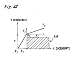
- the transfer head 85 is positioned in an arbitrary position on plane coordinates with the aid of a plurality of actuators 81 and 82 such as servomotors. For example, in moving the transfer head 85 from a plane coordinate P 0 (original position) to a plane coordinate P 2 (target position), if there is a region PAR that the transfer head 85 avoids passing in the middle of the linear travel route from the original position to the target position, positioning operation has been conducted by dividing the travel route into a route from the plane coordinate P 0 to an operation passing position P 1 and a route from the operation passing position P 1 to the target position P 2 as shown in Figs. 32 and 33 .
- a travel distance between P 0 - P 1 in X direction is referred to as X 1
- a travel distance between P 0 - P 1 in Y direction as Y 1 a travel distance between P 1 - P 2 in X direction as X 2
- Fig. 34 shows a driving pattern of the transfer head 85 in this case.
- a similar driving pattern is disclosed in the US Patent US5025362 , which relates to a coordinate measuring machine.
- each actuator such as a servomotor is tune-controlled so that timing of moving start and moving end between both P 0 - P 1 and P 1 - P 2 in X direction and Y direction is synchronous.
- a driving velocity can be a maximum velocity with use of the maximum acceleration in each moving operation in place of increased frequency of operation stop and start, as well as prolonged driving time and enlarged power consumption as with the case of the above-stated method.
- the present invention has the following constitutions.
- a positioning control method for controlling movement of a movable body from an original position to a target position by individually driving a plurality of drive units for moving the movable body in direction orthogonal to each other while avoiding passing of the movable body through a passing avoiding region, comprising:
- a positioning control method as defined in the first aspect further comprising:
- a positioning control method as defined in the second aspect, further comprising starting driving of the drive unit having the smaller travel distance from the original position to the operation passing position, later than operation timing of the drive unit having the longer travel distance by a calculated difference of necessary times for driving the respective drive units.
- driving start timing of the drive unit having smaller travel distance from the original position to the operation passing position is delayed by a specified period of time from driving start time of the drive unit having longer travel distance, which enables passing of the movable body through the operation passing position at a maximum velocity without performing acceleration and deceleration operations.
- This can implement high speed positioning control with low power consumption.
- each of the drive unit performs only one acceleration operation and only one deceleration operation in between the original position to the target position.
- one acceleration and deceleration operations make it possible to reach the target position. Accordingly, compared to the case of performing a plurality of acceleration and deceleration operations, driving efficiency can be increased and power consumption can be reduced.
- a positioning control method as defined in the fourth aspect, wherein the drive unit performs the acceleration and deceleration operations with constant acceleration.
- acceleration and deceleration operations till the target position are performed with constant acceleration.
- a positioning control method as defined in the fourth aspect, wherein the drive unit performs the acceleration and deceleration operations based on a preset velocity change pattern.
- a positioning control method as defined in the fourth aspect, wherein the drive unit performs the acceleration and deceleration operations based on a preset velocity change pattern including a curvilinear velocity change.
- acceleration and deceleration operations till the target position may be performed based on an arbitrary velocity change pattern, which facilitate setting of a desired acceleration and deceleration operations.
- a positioning control method as defined in the sixth or seventh aspect, wherein a velocity of the acceleration and deceleration operations based on the velocity change pattern is set with reference to a conversion table that defines a relation between a driving time and a travel amount within the driving time.
- a positioning control method as defined in the sixth or seventh aspect, wherein a necessary time for the drive unit to drive from the original position to the operation passing position based on the velocity change pattern is set with reference to a translation table that defines a relation between the travel amount and the driving time.
- a positioning control method as defined in the fifth or seventh aspect, wherein when the movable body passes the operation passing position, the both drive units drive for moving the movable body at a maximum velocity.
- the drive unit drives for moving the movable body during the acceleration and deceleration operations.
- a velocity is set with reference to the conversion table that defines a relation between the driving time and the travel amount, which facilitates driving control without complicated calculation, thereby implementing simplified driving control.
- a positioning control device for controlling movement of a movable body from an original position to a target position by individually driving a plurality of drive units for moving the movable body in direction orthogonal to each other while avoiding passing of the movable body through a passing avoiding region, comprising:
- driving start timing of the drive unit having smaller travel distance from the original position to the operation passing position is delayed by a specified period of time from driving start time of the drive unit having longer travel distance, which enables passing of the movable body through the operation passing position at a maximum velocity without performing acceleration and deceleration operations.
- This can implement high speed positioning control with low power consumption.
- a component mounting apparatus comprising:
- the setting section, the calculation section, and the command section perform driving control so as to pass the movable body through the operation passing position set by the setting section for avoiding the passing avoiding region at a maximum speed without performing acceleration and deceleration operations, thereby implementing high speed positioning with low power consumption.
- This enables positioning and mounting of electric components for a short period of time, resulting in increased mounting efficiency of components.
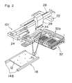
- Fig. 1 is a perspective view showing an electronic component mounting apparatus incorporating a positioning control device according to the first embodiment of the present embodiment
- Fig. 2 is a perspective view showing a transfer head included therein.
- the positioning control method is applied to an electronic component mounting apparatus
- the present invention is not limited to this example.
- the present invention may be applied, for example, to an assembly device for performing assembly with use of a transfer head that holds and transfers components.
- a pair of first guide rails 14A, second guide rails 14B, and third guide rails 14C each having a pair of conveyer belts for conveying a circuit board 12.
- the circuit board 12 is conveyed from the loader unit 16 to a pair of the second guide rails 14B of an XY table 18 in a mounting position of electric components.
- the mounted circuit board 12 is conveyed from the pair of the second guide rails 14B to the pair of the third guide rails 14C in an unloader unit 20 at the other end of the board conveyance route.
- the XY table 18 having the pair of the second guide rails 14B functions as an example of a board holding device, which can convey the circuit board 12 in orthogonal X and Y directions.
- the base 10 is further provided with an XY robot 101.
- the XY robot 101 is equipped with a pair of Y-axis robots 22 and 24 parallel to Y axis. On these two Y-axis robots 22 and 24, there is suspended an X-axis robot 26 parallel to X axis. Driving the Y-axis robots 22 and 24 moves the X-axis robot 26 over the Y-axis robots 22 and 24 in Y direction.
- the X-axis robot 26 is equipped with a transfer head 28 that exemplifies a movable body. Driving the X-axis robot 26 moves the transfer head 28 over the X-axis robot in X. direction. This makes it possible to move the transfer head 28 within an X-Y plane.
- the transfer head 28, that is mounted on the XY robot 101 composed of the X-axis robot 26 and the Y-axis robots 22 and 24 and freely moves on the X-Y plane (horizontal plane), is structured so as to suck desired electronic components one by one or in a batch in a simultaneous manner with use of a plurality of (ex.
- suction nozzles 34 from, for example, a part feeder 30 for feeding electronic components such as resistance chips and chip capacitors, or from a part tray unit 32 for feeding ICs such as SOP (small Outline Package) and QFP (Quad Flat Package) and relatively large electronic components such as connectors (the part feeder 30, the part tray unit 32, and the like are referred to as a component feed unit as a whole), and to respectively mount respective electronic components in specified locations on the circuit board 12.
- a control device 50 of Fig. 3 based on an operation procedure instructed by a mounting program 56 (see Fig. 3 ) preinstalled in a storage section 55 shown in Fig. 3 .
- a plurality of the part feeders 30 are provided in parallel on the lower left side of Fig. 1 in board conveyance direction of the second and third guide rails 14B and 14C.
- Each of the part feeders 30 is equipped with a tape-shaped component roll 30a accommodating electronic components such as resistance chips and chip capacitors.
- the part tray unit 32 is provided on the upper right side in Fig. 1 in board conveyance direction of the second and third guide rails 14B and 14C.
- Each tray 32a is structured so as to slide to the second and third guide rails 14B and 14C side depending on the feed number of components for keeping a component taking-out position in Y direction constant in order to steady a Y-directional position of the transfer head 28 for sucking components from the part tray unit 32.
- On the tray 32a there are mounted ICs such as SOP and QFP as well as relatively large electronic components such as connectors.
- a component recognizing device 36 for detecting two-dimensional deviation (suction attitude) of the electronic components sucked by the suction nozzle 34 so that the transfer head 28 can correct the position for canceling the deviation.
- a control device 50 performs overall control of the electronic component mounting apparatus 100 including control of a positioning control device 60, a suction nozzle Z-direction drive mechanism 51 for operating the suction nozzles 34 placed on the transfer head 28 in up-and-down direction, i.e., Z direction with use of an air cylinder or the like, conveyer belt drive mechanisms 52A, 52B, and 52C of the guide rails 14A, 14B, and 14C, a part feeder feed drive mechanism 53 for intermittently rotating the component roll 30a of the part feeder 30 so that the part feeder 30 performs component feeding operation, and a part tray feed drive mechanism 54 for sliding the tray 32a of the part tray unit 32 so that the part tray unit 32 performs component feed operation.
- the positioning control device 60 is composed of a main controller 1, a positioning controller 2, an X-axis driver 3, a Y-axis driver 4, an X-axis drive mechanism 5 for driving the X-axis robot 26, and a Y-axis drive mechanism 6 for driving the Y-axis robots 22 and 24.
- the control device 50 has a storage section 55, which stores information necessary for control.
- the control device 50 performs control by reading the information therefrom.
- the control device 50 reads a mounting program 56, which is stored in the storage section 55, and performs control so that electric components specified in the mounting program 56 are mounted on mounting coordinates in X and Y direction on the circuit board.
- the control device 50 instructs the positioning control device 60 to move the transfer head 28 to the X and Y coordinates specified in the mounting program 56.
- the control device 50 also executes correction of the X and Y coordinates specified in the mounting program 56 based on the deviation of an electronic component detected by the component recognizing device 36 and sucked by the suction nozzle 34, and gives instruction to the positioning control device 60 to move the transfer head 28 to the corrected X and Y coordinates.
- the control device 50 is further provided with an operation section 57 made up of such member as a CRT, a keyboard, or the like for operating the electronic component mounting apparatus 100, and an input/output section 58 for sending and receiving data such as the mounting program 56 to/from external devices.
- an operation section 57 made up of such member as a CRT, a keyboard, or the like for operating the electronic component mounting apparatus 100
- an input/output section 58 for sending and receiving data such as the mounting program 56 to/from external devices.
- the transfer head 28 Upon conveyance of the circuit board 12 from the first guide rails 14A of the loader unit 16 to the XY table 18 in a specified mounting position, the transfer head 28 moves within the XY plane by means of the XY robot 101, sucks a desired electronic component from the part feeder 30 or the part tray unit 32, moves over a posture recognition camera of the component recognizing device 36, checks a suction posture of the electronic component, and executes correction of the suction posture. After that, the transfer head 28 mounts the electronic component in a specified position on the circuit board 12.
- each mounting head sucks an electronic component from the part feeder 30 or the part tray unit 32 by means of the suction nozzle 34, or mounts the electronic component in a specified position on the circuit board 12, the suction nozzle 34 on the XY plane is lowered in vertical direction (Z direction). Depending on the types of electronic components, the suction nozzle 34 is appropriately replaced for performing placing operation.
- the mounting-completed circuit board 12 is carried out from the second guide rails 14B of the XY table 18 in the mounting position to the third guide rails 14C of the unloader unit 20, while a new circuit board 12 is carried in from the first guide rails 14A of the loader unit 16 to the second guide rails 14B of the XY table 18 in the mounting position, and the above stated mounting operations are repeated.
- the part tray unit 32 itself, for example, may be an obstacle of straightline travel of the transfer head 28.
- the region occupied by the part tray unit 32 is regarded as a passing avoiding region PAR. Consequently, the transfer head 28 needs to be moved with the part tray unit 32 being avoided like P 0 ⁇ P 1 ⁇ P 2 as shown in Fig. 2 .
- positioning control will be performed as shown below.
- the passing avoiding region PAR is herein exemplified by the region occupied by the part tray unit 32, it is not limited thereto, and any region which hinders straightline travel without uplift operation of the transfer head 28 in the light of mounting tact reduction may be regarded as the passing avoiding region PAR.
- the passing avoiding region PAR may be the region occupied by a replacing position of the suction nozzle 34 of the transfer head 28.
- the replacing position of the suction nozzle 34 there are spare nozzles 34 standby for replacement, which may hinder straightline travel of the transfer head 28.
- the passing avoiding region PAR may also be the region occupied by components already mounted on the circuit board 12.
- a tall component may hinder straightline travel of the transfer head 28, where moving the transfer head 28 on a route avoiding the component achieves faster mounting than moving the suction nozzle 34 up and down and moving the transfer head 28 straight while avoiding the component.
- the passing avoiding region PAR may also be the region occupied by part feeders.
- the passing avoiding region PAR may be provided to avoid interference with these other transfer heads 28 or to prepare for these other transfer heads coming to a standstill due to failure.
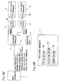
- Fig. 4A is a block diagram showing the structure of the positioning control device 60 for use in the electronic component mounting apparatus 100 in the first embodiment.
- the positioning control device 60 in the first embodiment is a control device for performing positioning control of the transfer head 28 which can move in X and Y directions that are orthogonal to each other.
- the positioning control device 60 is provided with: a main controller 1 for outputting respective commands of a moving target position P 2 of the transfer head 28, an operable maximum velocity V max of the transfer head 28, an operable maximum acceleration ⁇ max of the transfer head 28, an operation passing position P 1 for avoiding passing of the transfer head 28 through the passing avoiding region PAR, a specification axis A of the transfer head 28 for specifying delayed operation start based on later-described operation start delay time, and each operation start command C that is driving start timing of the transfer head 28; a positioning controller 2 for calculating a velocity value at which the transfer head 28 is moved in accordance with the command from the main controller 1, and outputting a velocity command based on the calculated velocity value; an X-axis driver 3 for individually driving and controlling an X-axis servomotor 5M as one example of a transfer head drive unit in accordance with the command from positioning controller 2; a Y-axis driver 4 for synchronously driving and controlling a pair of Y-axis servomotors 6M as an example
- the structure of the positioning controller 2 is shown in Fig. 4B .
- Numeral 120 denotes a setting section for setting the operation passing position P 1 of the transfer head 28 inputted by the main controller.
- 121 denotes a calculation section for calculating necessary time for driving each of the X-axis robot 26, and Y-axis robots 22 and 24 till the transfer head 28 passes the operation passing position P 1 (detailed description will be given later)
- 122 denotes a command section for giving velocity commands in consideration of drive start timing of each of X axis and Y axis based on the necessary time calculated in the calculation section 121.
- the main controller 1 outputs an operation passing position P 1 of the transfer head 28, a specification axis A, a target position P 2 of the transfer head 28 in movement, a maximum velocity V max of the transfer head 28 in movement, and a maximum acceleration ⁇ max of the transfer head 28 in movement, and outputs an operation start command C in response to an operation command based on the mounting program 56 from the electronic component mounting apparatus 100 (Step 11: hereinafter stated as S11).
- the positioning controller 2 determines whether or not the specification axis is set (S12).
- a conventional velocity command for example, in terms of the maximum velocity V max and the maximum acceleration ⁇ max shown in Fig. 35 is outputted (S13).
- each axis is driven by the positioning control method according to the first embodiment and positioning control of the transfer head 28 is performed.
- the necessary time for the transfer head 28 to move to the operation passing position P1 in each of X axis and Y axis is calculated based on an equation described later, and from an obtained difference of the necessary times, operation start delay time T is determined (S14). This operation will be described in detail later. Then, a velocity command based on the operation start delay time T, the maximum velocity V max , and the maximum acceleration ⁇ max is outputted (S15).
- Such control enables the X-axis drive mechanism 5 and the Y-axis drive mechanism 6 to simultaneously pass the operation passing position P 1 at the maximum velocity V max with acceleration is performed with the maximum acceleration ⁇ max to reach the maximum velocity V max without performing acceleration and deceleration operations.
- This makes it possible to carry the transfer head 28 to the target position P 2 with only one acceleration operation and only one deceleration operation performed during travel between the original position P 0 and the target position P 2 , thereby implementing high speed positioning control with low power consumption.
- Fig. 7 The procedure for determining operation start delay time in S14 is shown in the flow chart of Fig. 7 .
- Fig. 7 first, there is calculated necessary driving time t 1 for travel distance from the original position P 0 to the operation passing position P 1 in X direction, corresponding to the relation between X directional travel distance and Y directional travel distance from the original position P 0 to the operation passing position P 1 and each maximum acceleration ⁇ max of X axis and Y axis (specifically, X-directional maximum acceleration: ⁇ max and Y-directional maximum acceleration: ⁇ 2max ) and maximum velocity V max (specifically X-directional maximum velocity V 1max and Y-directional maximum velocity V 2max ) (S21).
- X-directional maximum acceleration: ⁇ max and Y-directional maximum acceleration: ⁇ 2max maximum velocity
- V max specifically X-directional maximum velocity V 1max and Y-directional maximum velocity V 2max
- Fig. 8 shows the specific outline of positioning control.
- the transfer head 28 is controlled separately along the X axis (X-axis robot 26) and Y axis (Y-axis robots 22 and 24) according to the relation between a time and a moving velocity shown in Fig. 8 .
- X-axis robot 26 X-axis robot 26
- Y-axis robots 22 and 24 Y-axis robots 22 and 24
- a necessary time for moving from the original position P 0 to the operation passing position P 1 is expressed as t 1
- a necessary time for moving from the original position P 0 to the operation passing position P 1 is expressed as t 2 .
- the specific method for calculating the driving start delay time is different by conditions including an original position, an operation passing position, a target position, a passing avoiding region PAR, and the like. Detailed description in each case will be given below.
- Fig. 9 is a comprehensive view showing a calculation method of necessary times t 1 and t 2 for moving the transfer head 28 from the original position P 0 to the operation passing position P 1 with constant acceleration during acceleration and deceleration operations and with constant velocity during other operation as shown in Fig. 8 in each expected case.
- reference character Sa denotes an integral value of a velocity, i.e., a travel distance from the operation start position to the operation passing position P 1
- reference character Sb denotes a travel distance of the transfer head 28 from the operation passing position to the operation end position.
- Reference character V denotes a maximum velocity V max of the transfer head 28, and ⁇ denotes a maximum acceleration ⁇ max of the transfer head 28.
- the first case is for performing positioning control with a velocity change pattern shown in Fig. 12 when an original position P 0 , an operation passing position P 1 , a target position P 2 , and a passing avoiding region PAR of the transfer head 28 are under the positional relation shown, for example, in Fig. 11 . More particularly, this is the case where the transfer head 28 passes the operation passing position P 1 located before the middle point of the total travel distance and after completion of acceleration.
- the change pattern of a moving velocity of the transfer head 28 along the Y axis in this case is that at the time of the output of an operation start command, acceleration is given with the maximum acceleration ⁇ max , the operation passing position P 1 is passed at the maximum velocity V max in a state where the transfer head 28 reaches the maximum velocity V max , deceleration is given before an operation end position P 2P , and termination is made in the position of P 2P .
- the change pattern along the X axis is that acceleration is given with the maximum acceleration ⁇ max after the lapse of operation start delay time T from the output of the operation start command, the operation passing position P 1 is passed at the maximum velocity V max in a state where the transfer head reaches the maximum velocity V max , deceleration is given before the target position P 2 , and termination is made in the position of P 2P .
- the acceleration at the time of deceleration is - ⁇ max and the operation start delay time T is given by
- Fig. 13 is a partial enlarged view showing the velocity change pattern within a necessary time t 2 along the Y axis of Fig. 12 .
- t 2 is considered to be divided into time in the period of acceleration t 5 and time in the period of constant velocity t 6 .
- a travel distance in the period of acceleration is expressed as Sa1
- a travel distance in the period of constant velocity is expressed as Sa2.
- the time t 5 is obtained from the travel distance Sa1
- the second case is for performing positioning control with a velocity change pattern shown in Fig. 14 when an original position P 0 , an operation passing position P 1 , a target position P 2 , and a passing avoiding region PAR of the transfer head 28 are under the positional relation shown, for example, in Fig. 14 . More particularly, this is the case where the transfer head 28 passes the operation passing position P 1 located before the middle point of the total travel distance and before completion of acceleration.
- the change pattern of a moving velocity of the transfer head 28 along the Y axis in this case is that at the time of the output of an operation start command, acceleration is given with the maximum acceleration ⁇ max , the operation passing position P 1 is passed before the maximum velocity V max is achieved, then, the maximum velocity V max is achieved, deceleration is given before an operation end position P 2P , and termination is made in the position of P 2P .
- the change pattern along the X axis is that acceleration is given with the maximum acceleration ⁇ max after the lapse of operation start delay time T from the output of the operation start command, the operation passing position P 1 is passed before the maximum velocity V max is achieved, then, the maximum velocity V max is achieved, deceleration is given before the target position P 2 , and termination is made in the position of P 2 .
- Fig. 16 is a partial enlarged view showing the velocity change pattern within a necessary time t 2 along the Y axis of Fig. 15 .
- the travel distance Sa in the period of acceleration is expressed as (Va/2)t 2 .
- Va ⁇ t 2
- the third case is for performing positioning control with a velocity change pattern shown in Fig. 18 when an original position P 0 , an operation passing position P 1 , a target position P 2 , and a passing avoiding region PAR of the transfer head 28 are under the positional relation shown, for example, in Fig. 17 . More particularly, this is the case where the transfer head 28 passes the operation passing position P 1 located after the middle point of the total travel distance and before start of deceleration.
- the change pattern of a moving velocity of the transfer head 28 along the Y axis in this case is that at the time of the output of an operation start command, acceleration is given with the maximum acceleration ⁇ max , the operation passing position P 1 is passed at the maximum velocity V max which has been achieved, deceleration is given before an operation end position P 2P , and termination is made in the position of P 2P .
- the change pattern along the X axis is that acceleration is given with the maximum acceleration ⁇ max after the lapse of operation start delay time T from the output of the operation start command, the operation passing position P 1 is passed at the maximum velocity V max which has been achieved, deceleration is given before the target position P 2 , and termination is made in the position of P 2 .
- Fig. 19 shows the velocity change pattern along the Y axis of Fig. 18 .
- t 2 is considered to be divided into time in the period of acceleration t 5 and time in the period of constant velocity t 6 .
- a travel distance in the period of velocity is expressed as Sa1
- a travel distance in the period of constant acceleration is expressed as Sa2.
- the time t 5 is obtained from the travel distance Sa1
- the fourth case is for performing positioning control with a velocity change pattern for X axis shown in Fig. 21 when an original position P 0 , an operation passing position P 1 , a target position P 2 , and a passing avoiding region PAR of the transfer head 28 are under the positional relation shown, for example, in Fig. 20 . More particularly, this is the case where the transfer head 28 passes the operation passing position P 1 located after the middle point of the total travel distance at a decelerated velocity slower than the maximum velocity, and where it is necessary to drive with the maximum acceleration at the time of driving start and to start deceleration before the maximum velocity is achieved.
- the change pattern of a moving velocity of the transfer head 28 along the X axis in this case is that acceleration is given with the maximum acceleration ⁇ max after the lapse of operation start delay time T from the output of the operation start command, the operation passing position P 1 is passed before the maximum velocity V max is achieved, deceleration is started at the time of passing the operation passing position P 1 , and termination is made in the position of P 2P .
- Fig. 22 is a view showing the velocity change pattern along the X axis of Fig. 21 .
- an acceleration period and a deceleration period are each expressed as t 7
- the time from the operation passing position P 1 to the operation end position P 2P is expressed as t 8 . Consequently, the necessary time t 1 is expressed as 2t 7 - t 8 .
- the fifth case is for performing positioning control with a velocity change pattern for Y axis shown in Fig. 21 when an original position P 0 , an operation passing position P 1 , a target position P 2 , and a passing avoiding region PAR of the transfer head 28 are under the positional relation shown in Fig. 20 similar to the fourth case. More particularly, this is the case where the transfer head 28 passes the operation passing position P 1 located after the middle point of the total travel distance at a decelerated velocity slower than the maximum velocity, and where driving with the maximum acceleration is made at the time of driving start and deceleration is started after the maximum velocity is achieved.
- the change pattern of a moving velocity of the transfer head 28 along the Y axis in this case is that acceleration is given with the maximum acceleration ⁇ max at the time of the output of an operation start command, the maximum velocity V max is achieved, then, the operation passing position P 1 is passed after the deceleration is started, and termination is made in the position of P 2 .
- Fig. 23 is a view showing the velocity change pattern along the Y axis of Fig. 21 .
- an acceleration period, a constant velocity period, and a deceleration period are each expressed as t 5 , t 9 , and t 10 .
- the time from the operation passing position P 1 to the operation end position P 2 is expressed as t 11 . Consequently, the necessary time t 2 is expressed as t 5 + t 9 + t 10 - t 11 .
- the moving time t 5 and t 10 are expressed as V/ ⁇
- the moving time t 9 is expressed as [S-2 ⁇ V 2 /(2 ⁇ ) ⁇ ]/V.
- the driving start time of the specification axis is delayed, so that the transfer head 28 can reach the target position with only one acceleration operation and only one deceleration operation performed both in X and Y directions, where the acceleration and deceleration operations are performed with the maximum acceleration, and the transfer head 28 moves at the maximum velocity during constant velocity operation.
- the positioning control method in the first embodiment disclosed above by delaying the driving start time of an axis set as the specification axis for specifying delayed driving start for the driving start delay time T, that is a difference of the necessary times t 1 and t 2 , timings of driving start and driving end are controlled, and it is so controlled that accelerated driving is made with the maximum acceleration to achieve the maximum velocity after driving start, and the operation passing position P 1 can be passed at the maximum velocity (provided that in the case of a short travel distance, deceleration may be given before the maximum velocity is achieved).
- the electronic component mounting apparatus 100 enables positioning and placing of electronic components sucked by the suction nozzle 34 in a placing position on the circuit board 12 for a short period of time, thereby increasing mounting efficiency and implementing tact up.
- FIG. 24A and 24B The structure of a positioning control device for use in an electronic component mounting apparatus in the second embodiment are shown in block diagrams of Figs. 24A and 24B .
- a conversion table 7 that defines the relation between a travel amount and a moving time is connected to a positioning controller 2 in a manner enabling input/output.
- the conversion table 7 facilitates driving of the transfer head 28, and enables driving with an arbitrary velocity change pattern such as a sigmoid driving type as shown in Fig. 25 , thereby implementing slow rising and falling, resulting in implementation of positioning with low vibration and noises.
- the conversion table 7 are used, as shown in Figs. 24A and 24B , for setting a velocity change pattern from driving start of the transfer head 28 to achievement of the maximum velocity, and from the maximum velocity to driving end of the transfer head 28 to a sigmoid driving type or the like for each of the X and Y axes robots 26, 22, and 24. More particularly, for facilitating driving control through simplification of operation processing for creation of driving signals, the travel amount and the moving time of the transfer head 28 during acceleration or deceleration with the velocity change patter of the sigmoid driving type are stored in advance as a table, with proper reference to which driving with a desired velocity change pattern is easily implemented.
- the positioning control device in the second embodiment referring to the conversion table 7 for calculating necessary time for a known travel distance to the operation passing position of the transfer head 28 makes it possible to clarify the relation between the driving time of the transfer head 28 and the travel distance by the driving, thereby facilitating setting of a driving time for the travel distance.
- Fig. 26 is a comprehensive view showing a calculation method of a necessary time t (t 1 , t 2 ) for moving the transfer head 28 of the electronic component mounting apparatus from the original position P 0 to the operation passing position P 1 with an arbitrary accelerating curve in each expected case.
- reference characters RaS and RaN denote an accelerated travel amount and acceleration time of the transfer head 28 obtained from the conversion table 7
- reference characters RdS and RdN denote a decelerated travel amount and deceleration time of the transfer head 28 obtained from the table 7.
- Reference character Tbl [ ] denotes a value obtained from the conversion table 7.
- the change pattern of a moving velocity of the transfer head 28 in this case is that the moving velocity of the transfer head 28 reaches the maximum velocity V max in the operation passing position P 1 as shown, for example, along only one axis in Fig. 27 .
- a necessary time t from the driving start position P 0 to the operation passing position P 1 is obtained by RaN + t 6 .
- the change pattern of a moving velocity of the transfer head 28 in this case is that for example, as shown in Fig. 28 , the moving velocity of the transfer head 28 does not yet reach the maximum velocity V max in the operation passing position P 1 .
- the change pattern of a moving velocity of the transfer head 28 in this case is that as shown in Fig. 29 , the moving velocity of the transfer head 28 equals the maximum velocity V max in the operation passing position P 1 .
- a necessary time t from the driving start position to the operation passing position P 1 is obtained by RaN + t 6 .
- t 6 is (Sa-RaS)/V
- the change pattern of a moving velocity of the transfer head 28 in this case is that as shown in Fig. 30 , deceleration is started before acceleration is made to the maximum velocity, and the moving velocity of the transfer head 28 is in the state of deceleration in the operation passing position P 1 .
- a necessary time t from the driving start position to the operation passing position P 1 can be obtained by 2t 7 - t 8 .
- the value t 7 is Sa/(RaS + RdS) times the time corresponding to the sum of RaN and RdN
- the value t 8 is Sb/RdS times the time corresponding to RdN.
- the change pattern of a moving velocity of the transfer head 28 in this case is that as shown in Fig. 31 , the moving velocity of the transfer head 28 is in the state of deceleration in the operation passing position P 1 .
- the positioning control device of the electronic component mounting apparatus in the second embodiment by delaying the driving start timing of an axis set as the specification axis for specifying delayed driving start for a difference of the necessary times t 1 and t 2 , moving operation is performed based on a preset arbitrary velocity pattern after start of driving, which brings about considerable decrease of vibration at the time of acceleration, and implements power saving due to shortened positioning time. Consequently, the electronic component mounting apparatus in the second embodiment enables positioning and placing of electronic components sucked by the suction nozzle 34 in a placing position on the circuit board 12 for a short period of time.
- driving start timing of the drive unit having a smaller travel distance from the original position of the movable body to the operation passing position is delayed by a specified period of time from driving start time of the drive unit having a longer travel distance, which enables passing of the movable body through the operation passing position set for avoiding the passing avoiding region PAR at the maximum velocity.
- This implements high speed positioning control with low power consumption.
- the driving control means so that the operation passing position set for avoiding the passing avoiding region PAR is passed at the maximum velocity without performing acceleration and deceleration operations, which enables high speed positioning with low power consumption.
- This enables positioning and placing of electric components sucked by the suction nozzle 34 in a placing position on the circuit board 12 for a short period of time, resulting in increased mounting efficiency of components.
- the present invention is not limited to the embodiment disclosed, but may be practiced in still other ways.
- the present invention is applied not only to the moving operation of the transfer head 28 from the sucking to placing operations, but also to the case of moving the transfer head 28 to the sucking position for sucking the next electronic component after one electronic component is placed onto a placing position of the circuit board 12.
Landscapes
- Engineering & Computer Science (AREA)
- Manufacturing & Machinery (AREA)
- Human Computer Interaction (AREA)
- Physics & Mathematics (AREA)
- General Physics & Mathematics (AREA)
- Automation & Control Theory (AREA)
- Robotics (AREA)
- Mechanical Engineering (AREA)
- Microelectronics & Electronic Packaging (AREA)
- Operations Research (AREA)
- Supply And Installment Of Electrical Components (AREA)
Claims (12)
- Positionssteuerverfahren zum Steuern der Bewegung eines bewegbaren Körpers (28) von einer ursprünglichen Position (P0) in eine Zielposition (P2) durch individuelles Antreiben einer Mehrzahl von Antriebseinheiten (5M, 6M) zum Bewegen des bewegbaren Körpers in Richtungen, die orthogonal zueinander stehen, wobei das Passieren des bewegbaren Körpers durch einen Passagevermeidungsbereich (PAR) verhindert wird,
wobei eine Betriebspassageposition (P1) eingestellt wird, die ein dazwischen liegender Passagepunkt auf einer Bewegungsroute des bewegbaren Körpers von der ursprünglichen Position (P0) in die Zielposition (P2) ist, und die Betriebspassageposition (P1) so definiert ist, dass sie den Passagevermeidungsbereich vermeidet, dadurch gekennzeichnet,
dass der Antrieb der Antriebseinheit mit einer kleineren Bewegungsdistanz von der ursprünglichen Position in die Betriebspassageposition später gestartet wird als die Antriebseinheit mit einer größeren Bewegungsdistanz, wobei - wenn der bewegliche Körper die Betriebspassageposition (P1) passiert - beide Antriebseinheiten (5M, 6M) den bewegbaren Körper antreiben, und
dass jede der Antriebseinheiten nur einen Beschleunigungsvorgang und einen Verzögerungsvorgang zwischen der ursprünglichen Position und der Zielposition durchführt. - Positionssteuerverfahren nach Anspruch 1, dadurch gekennzeichnet,
dass die notwendige Antriebszeit für die Bewegungsdistanz in jeder Antriebsrichtung zum Bewegen des bewegbaren Körpers von der ursprünglichen Position in die Betriebspassageposition berechnet wird, und
dass auf der Basis der berechneten notwendigen Antriebszeit jeder Antriebseinheit (5M, 6M) der Antrieb der Antriebseinheit mit der kleineren Bewegungsdistanz von der ursprünglichen Position in die Betriebspassageposition später gestartet wird als die Antriebseinheit mit einer größeren Bewegungsdistanz. - Positionssteuerverfahren nach Anspruch 2, dadurch gekennzeichnet, dass auf der Basis einer berechneten Differenz zwischen den notwendigen Antriebszeiten der entsprechenden Antriebseinheiten der Antrieb der Antriebseinheit mit der kleineren Bewegungsdistanz von der ursprünglichen Position in die Betriebspassageposition später gestartet wird als die Antriebseinheit mit der größeren Bewegungsdistanz.
- Positionssteuerverfahren nach Anspruch 1, dadurch gekennzeichnet, dass die Antriebseinheit die Beschleunigungs- und Verzögerungsvorgänge mit konstanter Beschleunigung durchführt.
- Positionssteuerverfahren nach Anspruch 1, dadurch gekennzeichnet, dass die Antriebseinheit die Beschleunigungs- und Verzögerungsvorgänge auf der Basis eines voreingestellten Geschwindigkeitsänderungsmusters durchführt.
- Positionssteuerverfahren nach Anspruch 1, dadurch gekennzeichnet, dass die Antriebseinheit die Beschleunigungs- und Verzögerungsvorgänge auf der Basis eines voreingestellten Geschwindigkeitsänderungsmusters einschließlich einer kurvenlinearen Geschwindigkeitsänderung durchführt.
- Positionssteuerverfahren nach Anspruch 5 oder 6, dadurch gekennzeichnet, dass eine Geschwindigkeit der Beschleunigungs- und Verzögerungsvorgänge auf der Basis des Geschwindigkeitsänderungsmusters unter Bezug auf eine Translationstabelle (7) eingestellt wird, die eine Beziehung zwischen einer Antriebszeit und einer Bewegungsgröße innerhalb der Antriebszeit definiert.
- Positionssteuerverfahren nach Anspruch 5 oder 6, dadurch gekennzeichnet, dass eine notwendige Zeit für die Antriebseinheit zum Antreiben von der ursprünglichen Position in die Betriebspassageposition auf der Basis des Geschwindigkeitsänderungsmusters unter Bezug auf eine Translationstabelle (7) eingestellt wird, die eine Beziehung zwischen der Bewegungsgröße und der Antriebszeit definiert.
- Positionssteuerverfahren nach Anspruch 4 oder 6, dadurch gekennzeichnet, dass die beiden Antriebseinheiten den bewegbaren Körper mit einer Maximalgeschwindigkeit bewegen, wenn der bewegbare Körper die Betriebspassageposition passiert.
- Positionssteuerverfahren nach Anspruch 4 oder 6, dadurch gekennzeichnet, dass die Antriebseinheit den bewegbaren Körper während der Beschleunigungs- und Verzögerungsvorgänge antreibt, wenn der bewegbare Körper die Betriebspassageposition passiert.
- Positionssteuervorrichtung zum Steuern der Bewegung eines bewegbaren Körpers (28) von einer ursprünglichen Position (P0) in eine Zielposition (P2) durch individuelles Antreiben einer Mehrzahl von Antriebseinheiten (5M, 6M) zum Bewegen des bewegbaren Körpers in Richtungen, die orthogonal zueinander stehen, wobei das Passieren des bewegbaren Körpers durch einen Passagevermeidungsbereich (PAR) verhindert wird,
mit einem Einstellabschnitt (120) zum Einstellen einer Betriebspassageposition (P1), die ein dazwischen liegender Passagepunkt auf einer Bewegungsroute des bewegbaren Körpers von der ursprünglichen Position (P0) in die Zielposition (P2) ist, wobei die Betriebspassageposition (P1) so definiert ist, dass sie den Passagevermeidungsbereich vermeidet,
mit einem Berechnungsabschnitt (121) zum Berechnen einer notwendigen Antriebszeit für jede Bewegungsdistanz in jeder Antriebsrichtung zum Bewegen des bewegbaren Körpers von ursprünglichen Position in die Betriebspassageposition, dadurch gekennzeichnet,
dass ein Befehlsabschnitt (122) vorgesehen ist, der auf der Basis der berechneten Differenz der notwendigen Zeiten zum Antreiben der entsprechenden Antriebseinheiten einen Befehl ausgibt zum späteren Starten des Antriebs der Antriebseinheit mit einer kleineren Bewegungsdistanz von der ursprünglichen Position in die Betriebspassageposition als die Antriebseinheit mit einer größeren Bewegungsdistanz, und einen Befehl ausgibt, durch den - wenn der bewegliche Körper die Betriebspassageposition (P1) passiert - beide Antriebseinheiten (5M, 6M) den bewegbaren Körper antreiben, und zum Befehlen, dass jede der Antriebseinheiten (5M, 6M) nur einen Beschleunigungsvorgang und einen Verzögerungsvorgang zwischen der ursprünglichen Position und der Zielposition durchführt. - Komponentenmontagevorrichtung
mit einer Komponentenzuführeinheit (30, 32) zum Zuführen von Komponenten,
mit einem Zuführkopf (28) zum Einsetzen der von der Komponentenzuführeinheit zugeführten Komponente in eine Schaltungsplatine (12),
mit einer Mehrzahl von Antriebseinheiten (5M, 6M) zum Antreiben des Zuführkopfes in zueinander orthogonalen Richtungen,
mit einer Positionssteuervorrichtung (60) zum Steuern der Bewegung des Zuführkopfes aus einer ursprünglichen Position in eine Zielposition (P2) mittels Durchführung einer individuellen Steuerung jeder der Antriebseinheiten, wobei vermieden wird, dass der Zuführkopf einen Passagevermeidungsbereich (PAR) durchläuft, und
mit einer Positionssteuervorrichtung nach Anspruch 11.
Applications Claiming Priority (5)
| Application Number | Priority Date | Filing Date | Title |
|---|---|---|---|
| JP2000008023 | 2000-01-17 | ||
| JP2000008023 | 2000-01-17 | ||
| JP2001005334 | 2001-01-12 | ||
| JP2001005334 | 2001-01-12 | ||
| PCT/JP2001/000214 WO2001054469A1 (fr) | 2000-01-17 | 2001-01-16 | Procede et dispositif de commande de positionnement et dispositif de montage de pieces electroniques mettant en oeuvre ledit dispositif de commande |
Publications (3)
| Publication Number | Publication Date |
|---|---|
| EP1255430A1 EP1255430A1 (de) | 2002-11-06 |
| EP1255430A4 EP1255430A4 (de) | 2004-06-16 |
| EP1255430B1 true EP1255430B1 (de) | 2008-07-02 |
Family
ID=26583641
Family Applications (1)
| Application Number | Title | Priority Date | Filing Date |
|---|---|---|---|
| EP01900778A Expired - Lifetime EP1255430B1 (de) | 2000-01-17 | 2001-01-16 | POSITIONIERUNGSSTEUERSYSTEME UND VORRICHTUNG, UND DAMIT AUSGERüSTETES BESTüCKUNGSVERFAHREN FüR ELEKTRONISCHE BAUTEILE. |
Country Status (5)
| Country | Link |
|---|---|
| US (1) | US7062334B2 (de) |
| EP (1) | EP1255430B1 (de) |
| JP (1) | JP4490022B2 (de) |
| DE (1) | DE60134627D1 (de) |
| WO (1) | WO2001054469A1 (de) |
Cited By (1)
| Publication number | Priority date | Publication date | Assignee | Title |
|---|---|---|---|---|
| CN101959399A (zh) * | 2009-07-14 | 2011-01-26 | Juki株式会社 | 电子部件搭载装置 |
Families Citing this family (19)
| Publication number | Priority date | Publication date | Assignee | Title |
|---|---|---|---|---|
| JP4478584B2 (ja) * | 2005-01-17 | 2010-06-09 | 株式会社ミツトヨ | 位置制御装置、測定装置および加工装置 |
| WO2006088032A2 (en) * | 2005-02-17 | 2006-08-24 | Matsushita Electric Industrial Co., Ltd. | Mounting condition determining method, mounting condition determining device, and mounting apparatus |
| GB0509450D0 (en) * | 2005-05-10 | 2005-06-15 | Europlacer Ind Sas | Method and apparatus |
| AU2006259258B2 (en) * | 2005-06-17 | 2010-04-01 | Edw. C. Levy Co. | Apparatus and method for shaping slabs of material |
| US7353135B2 (en) * | 2006-03-07 | 2008-04-01 | Robert Malm | Positioning and aligning the parts of an assembly |
| KR101220121B1 (ko) * | 2006-06-30 | 2013-01-11 | 스타 마이크로닉스 컴퍼니 리미티드 | 이동체의 이동 제어 장치, 이동체의 이동 제어 방법 및공작 기계의 이동 제어 장치 |
| JP4828356B2 (ja) * | 2006-08-29 | 2011-11-30 | ヤマハ発動機株式会社 | 電子部品取出装置、表面実装機、および電子部品取り出し方法 |
| US20100095553A1 (en) * | 2007-02-13 | 2010-04-22 | Alexander Elnekaveh | Resilient sports shoe |
| US20080189986A1 (en) * | 2007-02-13 | 2008-08-14 | Alexander Elnekaveh | Ventilated and resilient shoe apparatus and system |
| JP2008251997A (ja) * | 2007-03-30 | 2008-10-16 | Juki Corp | 部品実装装置の制御方法 |
| JP4889809B2 (ja) * | 2008-05-29 | 2012-03-07 | 三菱電機株式会社 | 加減速制御装置 |
| KR20110059713A (ko) * | 2008-09-09 | 2011-06-03 | 쿨리케 앤드 소파 다이 본딩 게엠베하 | 장치, 특히 다이본더의 배치 도구의 이동을 제어하기 위한 방법 |
| CN102414635B (zh) | 2009-04-28 | 2013-10-30 | 三菱电机株式会社 | 指令生成装置 |
| JP5678746B2 (ja) * | 2011-03-16 | 2015-03-04 | 株式会社デンソーウェーブ | ロボットの制御方法およびロボットの制御装置 |
| JP5678745B2 (ja) * | 2011-03-16 | 2015-03-04 | 株式会社デンソーウェーブ | ロボットの制御方法およびロボットの制御装置 |
| JP5686321B2 (ja) * | 2011-03-31 | 2015-03-18 | Jukiオートメーションシステムズ株式会社 | 実装装置、電子部品の実装方法及び基板の製造方法 |
| JP6396273B2 (ja) * | 2015-10-14 | 2018-09-26 | ファナック株式会社 | ワークとの干渉を避ける位置決めを行う数値制御装置 |
| US10082783B2 (en) * | 2015-12-17 | 2018-09-25 | Feng-Tien Chen | Computer numerical control servo drive system |
| JP7050219B2 (ja) * | 2017-09-25 | 2022-04-08 | パナソニックIpマネジメント株式会社 | 部品搭載装置および部品搭載方法 |
Family Cites Families (18)
| Publication number | Priority date | Publication date | Assignee | Title |
|---|---|---|---|---|
| US4415967A (en) * | 1981-06-02 | 1983-11-15 | Automation Industries, Inc. | Multi-axis controller |
| JPS58211211A (ja) | 1982-06-01 | 1983-12-08 | Fanuc Ltd | 数値制御方式 |
| US4565950A (en) * | 1982-11-09 | 1986-01-21 | Ricoh Company, Ltd. | Servo system |
| JPH063994B2 (ja) * | 1984-10-05 | 1994-01-12 | 株式会社日立製作所 | 複数台デイジタルサーボの制御方法 |
| US4706204A (en) * | 1985-03-05 | 1987-11-10 | Mitsubishi Denki Kabushiki Kaisha | Controller for movable robot for moving a work element through a continuous path |
| JP2552266B2 (ja) * | 1986-06-26 | 1996-11-06 | 富士通株式会社 | ロボツトの適応制御方法 |
| GB8626734D0 (en) * | 1986-11-08 | 1986-12-10 | Renishaw Plc | Coordinate positioning apparatus |
| JP3038972B2 (ja) * | 1991-04-03 | 2000-05-08 | ソニー株式会社 | 加減速パターン生成装置及びパターン生成方法 |
| JPH0511843A (ja) * | 1991-07-05 | 1993-01-22 | Fujitsu Ltd | ロボツトの軌道作成方法 |
| JPH05127718A (ja) | 1991-11-08 | 1993-05-25 | Fujitsu Ltd | マニピユレータの手先軌道自動生成装置 |
| US5610489A (en) * | 1994-08-26 | 1997-03-11 | Trinova Corporation | Method and apparatus for machine control |
| BE1009814A5 (nl) * | 1995-11-06 | 1997-08-05 | Framatome Connectors Belgium | Werkwijze en inrichting voor het aanbrengen van elektronische onderdelen in een plaat met gedrukte schakelingen. |
| US6128546A (en) * | 1996-09-30 | 2000-10-03 | Cincinnati Incorporated | Method and apparatus for a cutting system for avoiding pre-cut features |
| US6022132A (en) * | 1996-11-15 | 2000-02-08 | Thermwood Corporation | Method and apparatus for programming a CNC machine with a probe |
| US5886494A (en) * | 1997-02-06 | 1999-03-23 | Camelot Systems, Inc. | Positioning system |
| US6097168A (en) * | 1997-08-25 | 2000-08-01 | Toshiba Kikai Kabushiki Kaisha | Position control apparatus and method of the same, numerical control program preparation apparatus and method of the same, and methods of controlling numerical control machine tool |
| JP3297643B2 (ja) * | 1997-10-14 | 2002-07-02 | 東芝機械株式会社 | 送り駆動系のサーボ制御方法およびサーボ制御装置 |
| US5923132A (en) | 1998-04-23 | 1999-07-13 | Allen-Bradley Company, Llc | Method and apparatus for synchrononous multi-axis servo path planning |
-
2001
- 2001-01-16 WO PCT/JP2001/000214 patent/WO2001054469A1/ja active IP Right Grant
- 2001-01-16 DE DE60134627T patent/DE60134627D1/de not_active Expired - Lifetime
- 2001-01-16 EP EP01900778A patent/EP1255430B1/de not_active Expired - Lifetime
- 2001-01-16 US US10/181,198 patent/US7062334B2/en not_active Expired - Fee Related
- 2001-01-16 JP JP2001553354A patent/JP4490022B2/ja not_active Expired - Fee Related
Cited By (2)
| Publication number | Priority date | Publication date | Assignee | Title |
|---|---|---|---|---|
| CN101959399A (zh) * | 2009-07-14 | 2011-01-26 | Juki株式会社 | 电子部件搭载装置 |
| CN101959399B (zh) * | 2009-07-14 | 2014-12-17 | Juki株式会社 | 电子部件搭载装置 |
Also Published As
| Publication number | Publication date |
|---|---|
| US20030009260A1 (en) | 2003-01-09 |
| DE60134627D1 (de) | 2008-08-14 |
| US7062334B2 (en) | 2006-06-13 |
| EP1255430A1 (de) | 2002-11-06 |
| JP4490022B2 (ja) | 2010-06-23 |
| EP1255430A4 (de) | 2004-06-16 |
| WO2001054469A1 (fr) | 2001-07-26 |
Similar Documents
| Publication | Publication Date | Title |
|---|---|---|
| EP1255430B1 (de) | POSITIONIERUNGSSTEUERSYSTEME UND VORRICHTUNG, UND DAMIT AUSGERüSTETES BESTüCKUNGSVERFAHREN FüR ELEKTRONISCHE BAUTEILE. | |
| US5743005A (en) | Component mounting apparatus and method | |
| KR100532015B1 (ko) | 판상 부재의 반송지지장치 및 그 방법 | |
| CN101341587B (zh) | 电子部件的安装装置及安装方法 | |
| EP2890230B1 (de) | Optimierungsprogramm und substratverarbeitungssystem | |
| US6842974B1 (en) | Component mounting method and component mounting apparatus | |
| US6943521B2 (en) | Motor drive, motor drive control method, and component attaching device | |
| US6918176B2 (en) | Mounting apparatus of electronic parts and mounting methods of the same | |
| WO2001019156A1 (fr) | Procede et dispositif d'identification et de montage de pieces | |
| US10274929B2 (en) | Servo controller | |
| JPH11143544A (ja) | 部品搭載装置 | |
| JP2003078287A (ja) | 部品実装機の基板搬送方法及びその基板搬送装置 | |
| EP3522692B1 (de) | Montagevorrichtung und montageverfahren | |
| US10701850B2 (en) | Optimization program and mounting machine | |
| JP2017109289A (ja) | 生産装置モジュール、および生産装置ライン | |
| JP4523614B2 (ja) | 多軸コントローラ、その多軸コントローラを備えた実装装置及びその多軸コントローラを備えた塗布装置 | |
| JP4405012B2 (ja) | 部品認識方法及び部品実装方法 | |
| EP3713386B1 (de) | Berechnungsvorrichtung | |
| WO2022244034A1 (ja) | 部品移載装置 | |
| JP4737205B2 (ja) | 部品実装機の制御方法及び制御装置 | |
| JPH09181494A (ja) | チップ部品装着装置 | |
| JP3805512B2 (ja) | 位置決め制御方法 | |
| JP3611649B2 (ja) | 実装機の駆動制御方法及び同装置 | |
| CN113939181A (zh) | 部件安装装置以及部件安装方法 | |
| JP2006147624A (ja) | 電子部品実装装置 |
Legal Events
| Date | Code | Title | Description |
|---|---|---|---|
| PUAI | Public reference made under article 153(3) epc to a published international application that has entered the european phase |
Free format text: ORIGINAL CODE: 0009012 |
|
| 17P | Request for examination filed |
Effective date: 20020819 |
|
| AK | Designated contracting states |
Kind code of ref document: A1 Designated state(s): AT BE CH CY DE DK ES FI FR GB GR IE IT LI LU MC NL PT SE TR |
|
| RBV | Designated contracting states (corrected) |
Designated state(s): DE GB |
|
| A4 | Supplementary search report drawn up and despatched |
Effective date: 20040507 |
|
| RIC1 | Information provided on ipc code assigned before grant |
Ipc: 7B 25J 9/16 B Ipc: 7G 05B 19/4061 B Ipc: 7G 05B 19/416 B Ipc: 7H 05K 13/04 A |
|
| 17Q | First examination report despatched |
Effective date: 20060120 |
|
| GRAP | Despatch of communication of intention to grant a patent |
Free format text: ORIGINAL CODE: EPIDOSNIGR1 |
|
| GRAS | Grant fee paid |
Free format text: ORIGINAL CODE: EPIDOSNIGR3 |
|
| GRAA | (expected) grant |
Free format text: ORIGINAL CODE: 0009210 |
|
| AK | Designated contracting states |
Kind code of ref document: B1 Designated state(s): DE GB |
|
| REG | Reference to a national code |
Ref country code: GB Ref legal event code: FG4D |
|
| REF | Corresponds to: |
Ref document number: 60134627 Country of ref document: DE Date of ref document: 20080814 Kind code of ref document: P |
|
| RAP2 | Party data changed (patent owner data changed or rights of a patent transferred) |
Owner name: PANASONIC CORPORATION |
|
| PLBE | No opposition filed within time limit |
Free format text: ORIGINAL CODE: 0009261 |
|
| STAA | Information on the status of an ep patent application or granted ep patent |
Free format text: STATUS: NO OPPOSITION FILED WITHIN TIME LIMIT |
|
| 26N | No opposition filed |
Effective date: 20090403 |
|
| GBPC | Gb: european patent ceased through non-payment of renewal fee |
Effective date: 20090116 |
|
| PG25 | Lapsed in a contracting state [announced via postgrant information from national office to epo] |
Ref country code: GB Free format text: LAPSE BECAUSE OF NON-PAYMENT OF DUE FEES Effective date: 20090116 |
|
| PGFP | Annual fee paid to national office [announced via postgrant information from national office to epo] |
Ref country code: DE Payment date: 20140108 Year of fee payment: 14 |
|
| REG | Reference to a national code |
Ref country code: DE Ref legal event code: R119 Ref document number: 60134627 Country of ref document: DE |
|
| PG25 | Lapsed in a contracting state [announced via postgrant information from national office to epo] |
Ref country code: DE Free format text: LAPSE BECAUSE OF NON-PAYMENT OF DUE FEES Effective date: 20150801 |