EP1255091A1 - Kurvenannäherungsvorrichtung und damit ausgerüstetes Fahrzeug - Google Patents
Kurvenannäherungsvorrichtung und damit ausgerüstetes Fahrzeug Download PDFInfo
- Publication number
- EP1255091A1 EP1255091A1 EP02009146A EP02009146A EP1255091A1 EP 1255091 A1 EP1255091 A1 EP 1255091A1 EP 02009146 A EP02009146 A EP 02009146A EP 02009146 A EP02009146 A EP 02009146A EP 1255091 A1 EP1255091 A1 EP 1255091A1
- Authority
- EP
- European Patent Office
- Prior art keywords
- curve
- information
- navigation system
- vehicle
- control device
- Prior art date
- Legal status (The legal status is an assumption and is not a legal conclusion. Google has not performed a legal analysis and makes no representation as to the accuracy of the status listed.)
- Granted
Links
Images


Classifications
-
- G—PHYSICS
- G01—MEASURING; TESTING
- G01C—MEASURING DISTANCES, LEVELS OR BEARINGS; SURVEYING; NAVIGATION; GYROSCOPIC INSTRUMENTS; PHOTOGRAMMETRY OR VIDEOGRAMMETRY
- G01C21/00—Navigation; Navigational instruments not provided for in groups G01C1/00 - G01C19/00
- G01C21/26—Navigation; Navigational instruments not provided for in groups G01C1/00 - G01C19/00 specially adapted for navigation in a road network
- G01C21/28—Navigation; Navigational instruments not provided for in groups G01C1/00 - G01C19/00 specially adapted for navigation in a road network with correlation of data from several navigational instruments
-
- B—PERFORMING OPERATIONS; TRANSPORTING
- B60—VEHICLES IN GENERAL
- B60K—ARRANGEMENT OR MOUNTING OF PROPULSION UNITS OR OF TRANSMISSIONS IN VEHICLES; ARRANGEMENT OR MOUNTING OF PLURAL DIVERSE PRIME-MOVERS IN VEHICLES; AUXILIARY DRIVES FOR VEHICLES; INSTRUMENTATION OR DASHBOARDS FOR VEHICLES; ARRANGEMENTS IN CONNECTION WITH COOLING, AIR INTAKE, GAS EXHAUST OR FUEL SUPPLY OF PROPULSION UNITS IN VEHICLES
- B60K31/00—Vehicle fittings, acting on a single sub-unit only, for automatically controlling vehicle speed, i.e. preventing speed from exceeding an arbitrarily established velocity or maintaining speed at a particular velocity, as selected by the vehicle operator
- B60K31/0066—Vehicle fittings, acting on a single sub-unit only, for automatically controlling vehicle speed, i.e. preventing speed from exceeding an arbitrarily established velocity or maintaining speed at a particular velocity, as selected by the vehicle operator responsive to vehicle path curvature
-
- B—PERFORMING OPERATIONS; TRANSPORTING
- B60—VEHICLES IN GENERAL
- B60W—CONJOINT CONTROL OF VEHICLE SUB-UNITS OF DIFFERENT TYPE OR DIFFERENT FUNCTION; CONTROL SYSTEMS SPECIALLY ADAPTED FOR HYBRID VEHICLES; ROAD VEHICLE DRIVE CONTROL SYSTEMS FOR PURPOSES NOT RELATED TO THE CONTROL OF A PARTICULAR SUB-UNIT
- B60W2520/00—Input parameters relating to overall vehicle dynamics
- B60W2520/12—Lateral speed
- B60W2520/125—Lateral acceleration
-
- B—PERFORMING OPERATIONS; TRANSPORTING
- B60—VEHICLES IN GENERAL
- B60W—CONJOINT CONTROL OF VEHICLE SUB-UNITS OF DIFFERENT TYPE OR DIFFERENT FUNCTION; CONTROL SYSTEMS SPECIALLY ADAPTED FOR HYBRID VEHICLES; ROAD VEHICLE DRIVE CONTROL SYSTEMS FOR PURPOSES NOT RELATED TO THE CONTROL OF A PARTICULAR SUB-UNIT
- B60W2520/00—Input parameters relating to overall vehicle dynamics
- B60W2520/14—Yaw
Definitions
- the present invention relates to a curve approach control device for estimating and judging the approach of a curve ahead for a vehicle based on information from a navigation system, and warning alarms and controlling deceleration and so on, and a vehicle equipped with this curve approach control device.
- an appropriate vehicle approach speed is calculated according to road characteristics such as the radius of curvature of the curve based on information for a curve the vehicle is approaching provided by the navigation system.
- the driver is notified of this and is commanded to reduce speed, or control is exerted to automatically decelerate according to this command.
- map data for the navigation system is not usually updated with the most recent information, but is rather updated periodically. There are therefore many occasions where the road data for the navigation system and the actual shape of the road are not the same.
- a curve approach control device for predicting and judging the approach of a curve based on information for a curve ahead for a vehicle and outputting prescribed control commands comprises means for comparing and judging coincidence between curve information supplied by a navigation system and actual curve information based on actual vehicle behavior, and means for stopping outputting of the control commands when it is judged that the curve information from the navigation system and the actual curve information do not coincide.
- FIG. 1 to FIG. 4 The following is a description based on FIG. 1 to FIG. 4 of a preferred embodiment of the present invention.
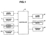
- numeral 10 is a controller constituting the main component of the curve approach control device and includes a microcomputer and other peripheral circuits.
- Information from sensors for detecting vehicle behavior such as a speed sensor 1, a yaw rate sensor 2, and a lateral acceleration sensor 3 and so on is inputted to the controller 10 either directly or through communication between units.
- Road information from a well-known navigation system 20 is also inputted through communication between the units.
- the controller 10 it is judged whether or not the vehicle equipped with the controller 10 can negotiate an approaching curve in a sufficiently stable manner based mainly on information from the navigation system 20, and an alarm device 30 such as a buzzer, a sound alarm or a warning light is driven as necessary in order to notify the driver.
- an alarm device 30 such as a buzzer, a sound alarm or a warning light is driven as necessary in order to notify the driver.
- the controller 10 When it is necessary to forcibly decelerate, the controller 10 outputs a decelerate command to a deceleration device 40 and control is then exerted to decelerate by shifting down the transmission, reducing engine torque, or by braking, and so on. Further, when the steering angle with respect to the curve is inappropriate to an extent that is considered to be unsafe, a steering angle correction command is outputted to a steering device 50 and steering is controlled.
- the reliability of curve information calculated based on road information from the navigation system 20 is then verified at the controller 10 using real curve information calculated from turning motion parameters expressing the actual behavior of the vehicle as detected by the sensors (navigation matching).
- data novigation data
- Control commands for alarms, deceleration and steering and the like are then halted for a set travel distance, set time, or until mismatching no longer applies, and erroneous operation is therefore prevented from occurring.
- the node number pertaining to the travel route of the vehicle, the latitude and longitude (east longitude, north latitude) of the vehicle position, data relating to a node directly after the vehicle, and data relating to a node for the travel route of the vehicle within a set range ahead for the vehicle are output from the navigation system 20 at intervals of prescribed distances so as to be included in information for the type of road and road width, and the like.
- the angle for every node and the curvature of the curve are calculated based on position information for every node sent from the navigation system 20, the total value (total navigation angle) of node angles for the same curve are obtained as curve depth, the node point having the largest curve curvature (smallest curve radius of curvature) within the same curve is detected, and the curvature of this node is obtained as the maximum navigation curvature.
- an interval Lp[j] between a node Pj(xp[j], yp[j]) and a previous node Pj-1(xp[j-1], yp[j-1]) is calculated for each node using the following equation (1) using node coordinates referencing the vehicle position sent from the navigation system 20.
- a node angle tp[j] for each node Pj is calculated using the following equation (2) based on the node coordinates, and radius of curvature rp[j] at node Pj is then calculated using the following equation (3) based on the results of this calculation.
- the node angle tp[j] obtained here is then expressed as a positive value in the case of a right corner and as a negative value in the case of a left corner.
- the maximum value of the curvature (maximum navigation curvature) s_nm_rnavi_max within the same curve is then obtained based on the results of the above calculation and the total navigation angle (curve depth) s_nm_tnavi is then obtained by adding previous node angles for each node for the plurality of nodes included in the same curve. Judgment of the same curve is carried out by identifying whether or not neighboring nodes are nodes making up the same curve based on node angles tp[j] for each node, each node interval Lp[j] and road width attribute information.
- a yaw rate ⁇ from the yaw rate sensor 2 is used at the controller 10 as a turning motion parameter expressing the actual behavior of the vehicle.
- the value ⁇ dt that is the integral of the yaw rate ⁇ at the section corresponding to navigation data for the same curve is then obtained as a yaw angle s_nm_psi corresponding to the curve depth (total navigation angle) s_nm_tnavi.
- a highest value (highest real curvature) s_nm_rpsi_max for a curvature obtained from actual vehicle behavior using turning radius ( ⁇ V/ ⁇ ) calculated from vehicle speed V from the speed sensor 1 and yaw rate ⁇ from the yaw rate sensor 2 is obtained as a parameter corresponding to the highest navigation curvature s_nm_rnavi_max.
- the highest real curvature can also be calculated from the speed and the lateral acceleration.
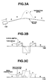
- FIG. 3A a description is given of the case where there is a curve shown by a solid line in the direction of travel of a vehicle 100.
- curve information shown by a dotted line is inputted from the navigation system 20
- a section B where curve information from the navigation system 20 and the actual curve of the road match as shown in FIG. 3B, an integral value of a yaw rate detected by the yaw rate sensor 2 gradually increases with respect to the curve depth obtained from the navigation data according to a change in the actual vehicle yaw rate and reaches a prescribed peak value so that the mutual differences are within the set range.
- FIG. 3A a description is given of the case where there is a curve shown by a solid line in the direction of travel of a vehicle 100.
- the real curvature based on actual vehicle behavior calculated from vehicle speed and yaw rate gradually increases with respect to the highest curvature of the curve (highest navigation curvature) obtained from the navigation data so as to reach a fixed value (highest real curvature) and the mutual differences are then within a set range. It is not therefore detected at this time that the navigation data and the actual vehicle behavior do not coincide.
- the real curvature calculated from the integral value of the yaw rate, the vehicle speed, and the yaw rate should change in the manner shown by the dotted line provided that the actual curve shape and the navigation data curve shape are substantially the same.
- change in the real curvature based on the integral value of the yaw rate, vehicle speed and yaw rate becomes small as shown by the solid lines in FIG. 3B and FIG.
- step S1 the controller 10 judges whether or not the current value for the total navigation angle s_nm_tnavi for this time has changed anew with respect to a saved value for the previous time based on node data from the navigation system 20.
- step S3 is proceeded to.
- step S2 is proceeded to, the saved value for the highest navigation curvature for the previous time and before is substituted with the value for this time, the highest navigation curvature s_nm_rnavi_max is updated, and step S3 is proceeded to.
- step S3 the controller 10 checks as to whether or not the value for this time has been changed from a prescribed value to zero, with the saved value for the previous time and before for the yaw angle s_nm_psi being a prescribed value other than zero. Namely, in this method, the controller 10 executes a separate routine to perform processing to integrate the yaw rate ⁇ supplied by the yaw rate sensor 2 and obtain a yaw angle s_nm_psi. When the yaw rate ⁇ is a prescribed value or less, this appears as a straight line and zero is substituted into the yaw angle s_nm_psi.
- step S7 is proceeded to and processing is carried out to verify the reliability of navigation data from the highest navigation curvature s_nm_rnavi_max and the highest curvature s_nm_rpsi_max.
- step S3 When the yaw angle s_nm_psi is changed to zero from the prescribed value, the controller 10 proceeds from step S3 to step S5 and a process is carried out to verify the reliability of navigation data from the total navigation angle (curve depth) s_nm_tnavi and the yaw angle s_nm_psi.
- step S5 it is judged whether or not the total navigation angle s_nm_tnavi and the yaw angle s_nm_psi match.
- step S8 is branched to, and the process of going through a control OFF evaluation process to suspend control commands for alarms, deceleration and steering and the like is carried out.
- the polarities of the total navigation angle s_nm_tnavi and the yaw angle s_nm_psi are different and if the mutual difference is slight, then there are cases where this is within the permitted range for matching even when the direction of the curve from the navigation system 20 and the direction of the curve obtained from the actual behavior of the vehicle do not match.
- the controller 10 performs evaluation taking non-matching of polarities as one condition for halting the outputting of control commands due to non-matching with the real curve information based on curve information from the navigation system 20 and actual vehicle behavior. Evaluation is performed here with regards to the polarity of the total navigation angle s_nm_tnavi and the polarity of the yaw angle s_nm_psi but the same also applies to the highest navigation curvature s_nm_rnavi_max and the highest real curvature s_nm_rpsi_max.
- step S6 is proceeded to from step S5 and a judgment is made as to whether or not an absolute value of the difference between the total navigation angle s_nm_tnavi and the yaw angle s_nm_psi is smaller than a judgment threshold value.
- step S6 when
- the routine for carrying out evaluation processing of the OFF control in step S8 is carried, and when the difference in the curvature ⁇ the judgment threshold value, the actual vehicle behavior matches with the navigation data, the navigation data is judged to be reliable, and the routine is executed as is.
- a reliability counter for counting reliability is provided and the control OFF evaluation processing is then carried out referring to this reliability counter.
- the value of the reliability counter is made to count up or to count down according to each of the judgment results with respect to the matching/non-matching of the mutual polarities of the highest navigation curvature s_nm_rnavi_max and the highest real curvature s_nm_rpsi_max, the matching/non-matching of the mutual polarities of the total navigation angle s_nm_tnavi and the yaw angle s_nm_psi, the difference between the total navigation angle s_nm_tnavi and the yaw angle s_nm_psi, and the differences between the curvatures for the highest navigation curvature s_nm_rnavi_max and the highest real curvature s_nm_rpsi_max.
- the period for which the control commands are halted may be extended over a prescribed time range or by a prescribed distance.
- the reliability of the navigation data is evaluated using both the difference between a curve depth (total navigation angle) based on the navigation data and a yaw angle based on actual vehicle behavior, and a difference between highest value (highest navigation curvature) of the curve curvature based on navigation data and a highest value (highest real curvature) of a curve curvature based on actual vehicle behavior.
- the reliability of the navigation data may also be evaluated using just one of these differences.
Applications Claiming Priority (2)
| Application Number | Priority Date | Filing Date | Title |
|---|---|---|---|
| JP2001130052 | 2001-04-26 | ||
| JP2001130052A JP4628583B2 (ja) | 2001-04-26 | 2001-04-26 | カーブ進入制御装置 |
Publications (2)
| Publication Number | Publication Date |
|---|---|
| EP1255091A1 true EP1255091A1 (de) | 2002-11-06 |
| EP1255091B1 EP1255091B1 (de) | 2013-03-13 |
Family
ID=18978492
Family Applications (1)
| Application Number | Title | Priority Date | Filing Date |
|---|---|---|---|
| EP02009146A Expired - Fee Related EP1255091B1 (de) | 2001-04-26 | 2002-04-24 | Kurvenannäherungsvorrichtung und damit ausgerüstetes Fahrzeug |
Country Status (3)
| Country | Link |
|---|---|
| US (1) | US6675090B2 (de) |
| EP (1) | EP1255091B1 (de) |
| JP (1) | JP4628583B2 (de) |
Cited By (4)
| Publication number | Priority date | Publication date | Assignee | Title |
|---|---|---|---|---|
| WO2004097453A1 (de) * | 2003-04-30 | 2004-11-11 | Robert Bosch Gmbh | Fahrerassistenzvorrichtung mit kursprädiktionsmodul |
| EP2022693A3 (de) * | 2007-07-31 | 2015-01-21 | Nissan Motor Co., Ltd. | Vorrichtung und Verfahren zur Fahrzeuglaufsteuerung |
| US9139173B2 (en) | 2008-10-28 | 2015-09-22 | Advics Co., Ltd. | Device for controlling traveling of vehicle |
| EP3037782A1 (de) * | 2014-12-23 | 2016-06-29 | HERE Global B.V. | Verfahren und vorrichtung zur bereitstellung einer lenkungszuverlässigkeitskarte auf basis gefahrener krümmungen und geometrischer krümmung |
Families Citing this family (30)
| Publication number | Priority date | Publication date | Assignee | Title |
|---|---|---|---|---|
| US7522091B2 (en) * | 2002-07-15 | 2009-04-21 | Automotive Systems Laboratory, Inc. | Road curvature estimation system |
| JP4069769B2 (ja) * | 2003-03-06 | 2008-04-02 | 日産自動車株式会社 | 道路形状認識装置 |
| JP4052963B2 (ja) * | 2003-03-13 | 2008-02-27 | 本田技研工業株式会社 | 車両の運動制御装置 |
| JP4175291B2 (ja) * | 2004-05-12 | 2008-11-05 | トヨタ自動車株式会社 | 車両の減速制御装置 |
| JP4441909B2 (ja) * | 2004-10-25 | 2010-03-31 | 株式会社デンソー | 車両制御装置 |
| EP1805530B1 (de) * | 2004-10-29 | 2010-12-29 | Continental Teves AG & Co. oHG | Verfahren zur erhöhung der fahrsicherheit und/oder des komforts eines kraftfahrzeugs |
| JP4639997B2 (ja) * | 2005-02-18 | 2011-02-23 | トヨタ自動車株式会社 | 車両の減速制御装置 |
| JP4434101B2 (ja) * | 2005-08-03 | 2010-03-17 | トヨタ自動車株式会社 | 車両用駆動力制御装置 |
| US7266438B2 (en) * | 2005-08-26 | 2007-09-04 | Gm Global Technology Operations, Inc. | Method of assisting driver to negotiate a roadway |
| US7561032B2 (en) * | 2005-09-26 | 2009-07-14 | Gm Global Technology Operations, Inc. | Selectable lane-departure warning system and method |
| US7792624B2 (en) * | 2005-10-05 | 2010-09-07 | Nissan Motor Co., Ltd. | Cruise control system |
| JP4818797B2 (ja) * | 2006-03-31 | 2011-11-16 | 本田技研工業株式会社 | 道路形状認識装置 |
| US7477988B2 (en) | 2006-05-16 | 2009-01-13 | Navteq North America, Llc | Dual road geometry representation for position and curvature-heading |
| CA2649990A1 (en) * | 2006-06-15 | 2007-12-21 | Uti Limited Partnership | Vehicular navigation and positioning system |
| KR101111072B1 (ko) * | 2006-06-30 | 2012-02-15 | 주식회사 만도 | 차량의 선회 감지방법 |
| JP4860391B2 (ja) * | 2006-07-27 | 2012-01-25 | 本田技研工業株式会社 | 車両の走行安全装置 |
| JP5061776B2 (ja) * | 2007-08-03 | 2012-10-31 | 日産自動車株式会社 | 車両用走行制御装置および車両用走行制御方法 |
| JP5139939B2 (ja) * | 2008-09-25 | 2013-02-06 | 日立オートモティブシステムズ株式会社 | 車両の減速支援装置 |
| US20100185389A1 (en) * | 2009-01-21 | 2010-07-22 | Michael Glenn Woodard | GPS-based vehicle alert and control system |
| US8630779B2 (en) * | 2010-04-09 | 2014-01-14 | Navteq B.V. | Method and system for vehicle ESC system using map data |
| US8437936B2 (en) * | 2010-04-09 | 2013-05-07 | Navteq B.V. | Method and system for vehicle ESC system using map data |
| JP5670840B2 (ja) * | 2011-07-05 | 2015-02-18 | 株式会社デンソーアイティーラボラトリ | 地図作成装置、方法及び車載用ナビゲーション装置 |
| JP5821959B2 (ja) * | 2011-07-21 | 2015-11-24 | 日産自動車株式会社 | 車両用走行制御装置、および走行路情報演算方法 |
| JP5700126B2 (ja) * | 2011-07-21 | 2015-04-15 | 日産自動車株式会社 | 車両用走行制御装置 |
| JP6026295B2 (ja) * | 2013-01-23 | 2016-11-16 | 株式会社デンソーアイティーラボラトリ | カーブ形状モデル化装置、方法及び車載用ナビゲーション装置 |
| JP6161942B2 (ja) * | 2013-04-19 | 2017-07-12 | 株式会社デンソーアイティーラボラトリ | カーブ形状モデル化装置、車両情報処理システム、カーブ形状モデル化方法、及びカーブ形状モデル化プログラム |
| JP6412460B2 (ja) * | 2015-04-14 | 2018-10-24 | 株式会社Soken | 走行路推定装置 |
| DE102017212254A1 (de) | 2017-07-18 | 2019-01-24 | Volkswagen Aktiengesellschaft | Prädiktive Streckenführung eines Fahrzeugs |
| JP2019043428A (ja) * | 2017-09-05 | 2019-03-22 | 三菱電機株式会社 | 車両制御装置および車両制御方法 |
| CN109814575B (zh) * | 2019-02-22 | 2022-04-08 | 百度在线网络技术(北京)有限公司 | 自动驾驶车辆变道路线规划方法、装置以及终端 |
Citations (8)
| Publication number | Priority date | Publication date | Assignee | Title |
|---|---|---|---|---|
| EP0819912A2 (de) * | 1996-07-15 | 1998-01-21 | Toyota Jidosha Kabushiki Kaisha | Fahrzeugfahrzustandsvorhersagevorrichtung und Warnvorrichtung, welche die Vorrichtung verwendet |
| EP0901929A1 (de) * | 1997-09-10 | 1999-03-17 | Fuji Jukogyo Kabushiki Kaisha | Vorrichtung zum Steuern der Bewegung eines Fahrzeuges |
| EP0933272A2 (de) * | 1998-01-29 | 1999-08-04 | Fuji Jukogyo Kabushiki Kaisha | Dynamisches Kraftfahrzeugsteuerungssystem |
| EP1074421A2 (de) * | 1999-08-06 | 2001-02-07 | Fuji Jukogyo Kabushiki Kaisha | Steuervorrichtung zur Erkennung des Anfangs einer Kurvenfahrt |
| EP1083535A2 (de) * | 1999-09-09 | 2001-03-14 | Fuji Jukogyo Kabushiki Kaisha | Kurvennäherungssteuervorrichtung |
| EP1085296A2 (de) * | 1999-09-14 | 2001-03-21 | Fuji Jukogyo Kabushiki Kaisha | Kurvenannäherungssteuervorrichtung |
| EP1086844A2 (de) * | 1999-09-21 | 2001-03-28 | Fuji Jukogyo Kabushiki Kaisha | Vorrichtung zur Ermittlung einer Strassenkrümmung und zum Regeln der Geschwindigkeit bei Annäherung an eine Kurve |
| EP1087358A2 (de) * | 1999-09-22 | 2001-03-28 | Fuji Jukogyo Kabushiki Kaisha | Kurvennäherungssteuervorrichtung |
Family Cites Families (10)
| Publication number | Priority date | Publication date | Assignee | Title |
|---|---|---|---|---|
| JP3133770B2 (ja) | 1991-01-18 | 2001-02-13 | マツダ株式会社 | 自動車の走行システム |
| JP3366043B2 (ja) * | 1993-03-26 | 2003-01-14 | 本田技研工業株式会社 | 車両の通過可能車速設定装置 |
| JP3269927B2 (ja) * | 1994-11-30 | 2002-04-02 | 本田技研工業株式会社 | 車両の操舵制御装置 |
| JP3336793B2 (ja) * | 1995-01-21 | 2002-10-21 | 三菱自動車工業株式会社 | 自動車の前方道路状況対応制御装置 |
| JP3366220B2 (ja) * | 1997-05-26 | 2003-01-14 | 本田技研工業株式会社 | 道路形状判定装置及び車両制御装置 |
| JP3366225B2 (ja) * | 1997-07-09 | 2003-01-14 | 本田技研工業株式会社 | ナビゲーション装置及び車両制御装置 |
| JP3378490B2 (ja) * | 1998-01-29 | 2003-02-17 | 富士重工業株式会社 | 道路情報認識装置 |
| JP3926472B2 (ja) * | 1998-04-28 | 2007-06-06 | 株式会社エクォス・リサーチ | 車両制御装置及びそのプログラムを記録した記録媒体 |
| JP3167989B2 (ja) * | 1999-08-10 | 2001-05-21 | 富士重工業株式会社 | カーブ進入制御装置 |
| JP3341999B2 (ja) * | 1999-08-31 | 2002-11-05 | 富士重工業株式会社 | 道路形状推定装置 |
-
2001
- 2001-04-26 JP JP2001130052A patent/JP4628583B2/ja not_active Expired - Fee Related
-
2002
- 2002-04-15 US US10/123,125 patent/US6675090B2/en not_active Expired - Lifetime
- 2002-04-24 EP EP02009146A patent/EP1255091B1/de not_active Expired - Fee Related
Patent Citations (8)
| Publication number | Priority date | Publication date | Assignee | Title |
|---|---|---|---|---|
| EP0819912A2 (de) * | 1996-07-15 | 1998-01-21 | Toyota Jidosha Kabushiki Kaisha | Fahrzeugfahrzustandsvorhersagevorrichtung und Warnvorrichtung, welche die Vorrichtung verwendet |
| EP0901929A1 (de) * | 1997-09-10 | 1999-03-17 | Fuji Jukogyo Kabushiki Kaisha | Vorrichtung zum Steuern der Bewegung eines Fahrzeuges |
| EP0933272A2 (de) * | 1998-01-29 | 1999-08-04 | Fuji Jukogyo Kabushiki Kaisha | Dynamisches Kraftfahrzeugsteuerungssystem |
| EP1074421A2 (de) * | 1999-08-06 | 2001-02-07 | Fuji Jukogyo Kabushiki Kaisha | Steuervorrichtung zur Erkennung des Anfangs einer Kurvenfahrt |
| EP1083535A2 (de) * | 1999-09-09 | 2001-03-14 | Fuji Jukogyo Kabushiki Kaisha | Kurvennäherungssteuervorrichtung |
| EP1085296A2 (de) * | 1999-09-14 | 2001-03-21 | Fuji Jukogyo Kabushiki Kaisha | Kurvenannäherungssteuervorrichtung |
| EP1086844A2 (de) * | 1999-09-21 | 2001-03-28 | Fuji Jukogyo Kabushiki Kaisha | Vorrichtung zur Ermittlung einer Strassenkrümmung und zum Regeln der Geschwindigkeit bei Annäherung an eine Kurve |
| EP1087358A2 (de) * | 1999-09-22 | 2001-03-28 | Fuji Jukogyo Kabushiki Kaisha | Kurvennäherungssteuervorrichtung |
Cited By (7)
| Publication number | Priority date | Publication date | Assignee | Title |
|---|---|---|---|---|
| WO2004097453A1 (de) * | 2003-04-30 | 2004-11-11 | Robert Bosch Gmbh | Fahrerassistenzvorrichtung mit kursprädiktionsmodul |
| EP2022693A3 (de) * | 2007-07-31 | 2015-01-21 | Nissan Motor Co., Ltd. | Vorrichtung und Verfahren zur Fahrzeuglaufsteuerung |
| US9139173B2 (en) | 2008-10-28 | 2015-09-22 | Advics Co., Ltd. | Device for controlling traveling of vehicle |
| EP2340975A4 (de) * | 2008-10-28 | 2018-02-28 | Advics Co., Ltd. | Vorrichtung zur steuerung des fahrwegs eines fahrzeugs |
| EP3037782A1 (de) * | 2014-12-23 | 2016-06-29 | HERE Global B.V. | Verfahren und vorrichtung zur bereitstellung einer lenkungszuverlässigkeitskarte auf basis gefahrener krümmungen und geometrischer krümmung |
| US9562779B2 (en) | 2014-12-23 | 2017-02-07 | Here Global B.V. | Method and apparatus for providing a steering reliability map based on driven curvatures and geometry curvature |
| US9880555B2 (en) | 2014-12-23 | 2018-01-30 | Here Global B.V. | Method and apparatus for providing a steering reliability map based on driven curvatures and geometry curvature |
Also Published As
| Publication number | Publication date |
|---|---|
| EP1255091B1 (de) | 2013-03-13 |
| JP4628583B2 (ja) | 2011-02-09 |
| US6675090B2 (en) | 2004-01-06 |
| US20020161510A1 (en) | 2002-10-31 |
| JP2002329299A (ja) | 2002-11-15 |
Similar Documents
| Publication | Publication Date | Title |
|---|---|---|
| US6675090B2 (en) | Curve approach device, and vehicle equipped with curve approach device | |
| EP1087358B1 (de) | Kurvennäherungssteuervorrichtung | |
| JP6438516B2 (ja) | 車両の走行制御装置 | |
| JP3349120B2 (ja) | カーブ進入制御装置 | |
| JP3494395B2 (ja) | 車両運動制御装置 | |
| JP3378490B2 (ja) | 道路情報認識装置 | |
| US20100023232A1 (en) | Vehicle travel speed control method | |
| US8010280B2 (en) | Vehicle travel safety device | |
| JP3167990B2 (ja) | カーブ進入制御装置 | |
| JP2001093095A (ja) | 道路形状推定装置及びそれを用いたカーブ進入制御装置 | |
| JP2001052300A (ja) | カーブ進入制御装置 | |
| JP6755071B2 (ja) | 車両の走行制御装置 | |
| US11904936B2 (en) | Driving support device for vehicle | |
| US7764192B2 (en) | Traveling safety device for vehicle | |
| JP2020056785A (ja) | 車両を運転するための方法および装置 | |
| US11267488B2 (en) | Automatic driving control apparatus for vehicle | |
| US20210078604A1 (en) | Automatic driving control apparatus for vehicle | |
| JP7160706B2 (ja) | 道路認識装置 | |
| JP2009298193A (ja) | 車両の運転支援装置 | |
| JP7467522B2 (ja) | 車両制御装置 | |
| JP2007122155A (ja) | 分岐路進入推定装置 | |
| JP3983727B2 (ja) | 車両運動制御装置 | |
| JP2001093093A (ja) | カーブ進入制御装置 | |
| JP3503462B2 (ja) | カーブ検出装置 | |
| US20240035846A1 (en) | Method and device for determining the reliability of a low-definition map |
Legal Events
| Date | Code | Title | Description |
|---|---|---|---|
| PUAI | Public reference made under article 153(3) epc to a published international application that has entered the european phase |
Free format text: ORIGINAL CODE: 0009012 |
|
| AK | Designated contracting states |
Kind code of ref document: A1 Designated state(s): AT BE CH CY DE DK ES FI FR GB GR IE IT LI LU MC NL PT SE TR |
|
| AX | Request for extension of the european patent |
Free format text: AL;LT;LV;MK;RO;SI |
|
| 17P | Request for examination filed |
Effective date: 20020924 |
|
| AKX | Designation fees paid |
Designated state(s): DE FR GB |
|
| 17Q | First examination report despatched |
Effective date: 20080610 |
|
| GRAP | Despatch of communication of intention to grant a patent |
Free format text: ORIGINAL CODE: EPIDOSNIGR1 |
|
| GRAS | Grant fee paid |
Free format text: ORIGINAL CODE: EPIDOSNIGR3 |
|
| GRAA | (expected) grant |
Free format text: ORIGINAL CODE: 0009210 |
|
| AK | Designated contracting states |
Kind code of ref document: B1 Designated state(s): DE FR GB |
|
| REG | Reference to a national code |
Ref country code: GB Ref legal event code: FG4D Ref country code: DE Ref legal event code: R081 Ref document number: 60244628 Country of ref document: DE Owner name: SUBARU CORPORATION, JP Free format text: FORMER OWNER: FUJI JUKOGYO K.K., TOKIO/TOKYO, JP |
|
| REG | Reference to a national code |
Ref country code: DE Ref legal event code: R096 Ref document number: 60244628 Country of ref document: DE Effective date: 20130508 |
|
| PLBE | No opposition filed within time limit |
Free format text: ORIGINAL CODE: 0009261 |
|
| STAA | Information on the status of an ep patent application or granted ep patent |
Free format text: STATUS: NO OPPOSITION FILED WITHIN TIME LIMIT |
|
| REG | Reference to a national code |
Ref country code: FR Ref legal event code: ST Effective date: 20131231 |
|
| 26N | No opposition filed |
Effective date: 20131216 |
|
| GBPC | Gb: european patent ceased through non-payment of renewal fee |
Effective date: 20130613 |
|
| PG25 | Lapsed in a contracting state [announced via postgrant information from national office to epo] |
Ref country code: FR Free format text: LAPSE BECAUSE OF NON-PAYMENT OF DUE FEES Effective date: 20130513 |
|
| REG | Reference to a national code |
Ref country code: DE Ref legal event code: R097 Ref document number: 60244628 Country of ref document: DE Effective date: 20131216 |
|
| PG25 | Lapsed in a contracting state [announced via postgrant information from national office to epo] |
Ref country code: GB Free format text: LAPSE BECAUSE OF NON-PAYMENT OF DUE FEES Effective date: 20130613 |
|
| REG | Reference to a national code |
Ref country code: DE Ref legal event code: R082 Ref document number: 60244628 Country of ref document: DE Representative=s name: MEISSNER BOLTE PATENTANWAELTE RECHTSANWAELTE P, DE Ref country code: DE Ref legal event code: R081 Ref document number: 60244628 Country of ref document: DE Owner name: SUBARU CORPORATION, JP Free format text: FORMER OWNER: FUJI JUKOGYO KABUSHIKI KAISHA, TOKYO, JP |
|
| PGFP | Annual fee paid to national office [announced via postgrant information from national office to epo] |
Ref country code: DE Payment date: 20170420 Year of fee payment: 16 |
|
| REG | Reference to a national code |
Ref country code: DE Ref legal event code: R119 Ref document number: 60244628 Country of ref document: DE |
|
| PG25 | Lapsed in a contracting state [announced via postgrant information from national office to epo] |
Ref country code: DE Free format text: LAPSE BECAUSE OF NON-PAYMENT OF DUE FEES Effective date: 20181101 |