EP1249397B1 - Verschnürungsmaschine mit Bandführungskanal - Google Patents
Verschnürungsmaschine mit Bandführungskanal Download PDFInfo
- Publication number
- EP1249397B1 EP1249397B1 EP01125171A EP01125171A EP1249397B1 EP 1249397 B1 EP1249397 B1 EP 1249397B1 EP 01125171 A EP01125171 A EP 01125171A EP 01125171 A EP01125171 A EP 01125171A EP 1249397 B1 EP1249397 B1 EP 1249397B1
- Authority
- EP
- European Patent Office
- Prior art keywords
- band
- strapping
- guide
- driving
- shaft
- Prior art date
- Legal status (The legal status is an assumption and is not a legal conclusion. Google has not performed a legal analysis and makes no representation as to the accuracy of the status listed.)
- Expired - Lifetime
Links
Images


Classifications
-
- B—PERFORMING OPERATIONS; TRANSPORTING
- B65—CONVEYING; PACKING; STORING; HANDLING THIN OR FILAMENTARY MATERIAL
- B65B—MACHINES, APPARATUS OR DEVICES FOR, OR METHODS OF, PACKAGING ARTICLES OR MATERIALS; UNPACKING
- B65B13/00—Bundling articles
- B65B13/02—Applying and securing binding material around articles or groups of articles, e.g. using strings, wires, strips, bands or tapes
- B65B13/04—Applying and securing binding material around articles or groups of articles, e.g. using strings, wires, strips, bands or tapes with means for guiding the binding material around the articles prior to severing from supply
- B65B13/06—Stationary ducts or channels
-
- B—PERFORMING OPERATIONS; TRANSPORTING
- B65—CONVEYING; PACKING; STORING; HANDLING THIN OR FILAMENTARY MATERIAL
- B65B—MACHINES, APPARATUS OR DEVICES FOR, OR METHODS OF, PACKAGING ARTICLES OR MATERIALS; UNPACKING
- B65B13/00—Bundling articles
- B65B13/18—Details of, or auxiliary devices used in, bundling machines or bundling tools
- B65B13/22—Means for controlling tension of binding means
-
- B—PERFORMING OPERATIONS; TRANSPORTING
- B65—CONVEYING; PACKING; STORING; HANDLING THIN OR FILAMENTARY MATERIAL
- B65B—MACHINES, APPARATUS OR DEVICES FOR, OR METHODS OF, PACKAGING ARTICLES OR MATERIALS; UNPACKING
- B65B13/00—Bundling articles
- B65B13/18—Details of, or auxiliary devices used in, bundling machines or bundling tools
- B65B13/24—Securing ends of binding material
- B65B13/32—Securing ends of binding material by welding, soldering, or heat-sealing; by applying adhesive
Definitions
- a strapping band is fed to a band guide in an arch member to wind the band around an article to be strapped, and the strapping band is cut and bonded to form a loop, whereby the article is strapped.
- Such arch type strapping machine is provided with a sealing mechanism for the strapping band.
- the sealing mechanism comprises a first gripper (hereinbelow, referred to as a right gripper) for fixing a top end of the strapping band fed into the band guide, a second gripper (hereinbelow, referred to as a left gripper) for fixing a rear portion of the strapping band after the band has been pulled back to be tightened and a compression head for compressing and bonding (in many cases, melt-bonding) the top end and the rear portion of the strapping band and cutting the rear portion of the band.
- the right gripper, the left gripper and the compression head are operated by driving cams attached to a shaft for sealing which is rotated and driven by a motor for sealing.
- Prior art document DE 19 850 935 discloses a strapping machine according to the preamble of claim 1.
- an article is strapped by performing a band feeding step for feeding a strapping band into a band guide in an arch member, a first tightening step for winding the strapping band around an article to be strapped by returning quickly the band fed into the band guide, a second tightening step for tightening strongly the strapping band wound around the article by returning the band, and a step for bonding (in many cases, melt-bonding) a rear portion and a top end of the band wound around the article to be strapped and cutting the band.
- the band feeding step and the first and second tightening steps are carried out by a driving mechanism comprising a plurality of rollers for running and tightening the strapping band.
- Such driving mechanism for the strapping band makes the size of the arch type strapping machine large because a plurality of driving rollers are used, e.g., a driving roller for performing the band feeding step as well as the first tightening step and a driving roller for performing the second tightening step being provided separately. Accordingly, this is contrary to a demand of reducing the size of the arch type strapping machine.
- an article is strapped with a strapping band in such a manner that the strapping band is fed into a groove formed in a band guide having a channel-like shape in cross section, an open side of which is pushed to an inner surface of the arch member; the strapping band fed into the band guide is wound around the article to be strapped by returning the band at a high speed; the strapping band wound around the article is tightened by pulling it back, and the cutting of a rear portion of the band and bonding (melt-bonding) of the rear portion to an top end of the band is conducted.
- the returning of the strapping band at a high speed is conducted immediately after the state that the strapping band leaves entirely or partly from the band guide, such state being obtainable by opening forcibly the band guide in a direction departing from the inner surface of the arch member with which the band guide is brought into contact.
- the width or the height (in particular, the height) of the groove of the band guide is formed to be relatively small so that the strapping band can be certainly passed without causing the bending of a top end of the band.
- the strapping band follows the movement of the band guide due to a frictional force between an inner surface of the groove and the strapping band, and the band remains in the groove. If the strapping band is tightened at a high speed in the state that the strapping band remains in the groove, an unusual deformation is caused instantaneously in the band guide at the time of leaving the strapping band, whereby the band guide is damaged.
- the strapping band is rewound from a band roll fitted to a band reel which is attached to an outer side of the arch type strapping machine, to be stored temporarily in a band accommodation chamber in the strapping machine. Then, the strapping band in the band accommodation chamber is successively fed into the band guide.
- the band reel comprises a supporting shaft having an end supported by the main body of the strapping machine, a reed portion attached to the supporting shaft so that at least a part (in many cases, a rear side plate) is removable from the supporting shaft, the reel portion being adapted to mount the band roll for the strapping band, and a nob attached to a rear end of the supporting shaft to fix the reel portion.
- the structure for fitting the nob to the supporting shaft comprises a male screw formed in a rear end (the free end) of the supporting shaft and a female screw formed in the nob so that the nob can be fitted to the supporting shaft by rotating it several times of turn. Accordingly, in the replacement of the band roll, it is necessary to turn back the tightly fastened nob, and the nob is tightly fastened by rotating after new band roll is mounted. Accordingly, the working for replacing the band roll is troublesome.
- an object of the present invention to provide an arch type strapping machine having a strapping band driving mechanism for feeding the strapping band into the band guide and pulling back the band, which is suitable for reducing the size of the strapping machine.
- an object of the present invention to provide an arch type strapping machine having a band reel adapted to mount a band roll on which the strapping band fed into the band guide is wound, which permits the fitting and the removal of a nob easily.
- an object of the present invention to provide an arch type strapping machine having a band driving-out device which can provide a state that the strapping band leaves certainly from a groove for receiving the band at the time of opening the band guide without losing a smooth opening operation of the band guide.
- an arch type strapping machine having a sealing mechanism which comprises a right gripper for fixing a top end of a strapping band fed into a band guide of the arch type strapping machine; a left gripper for fixing a rear portion of the strapping band after the strapping band has been wound around an article to be strapped and tightened; a compression head for compressing and bonding the top end and the rear portion of the strapping band and cutting the rear portion of the band, and a driving means for operating the right gripper, the left gripper and the compression head, said arch type strapping machine being characterized in that the driving means of the sealing mechanism comprises a first driving section for operating the right gripper and a second driving section for operating the left gripper and the compression head, wherein the second driving section comprises a motor for sealing, a shaft for sealing rotated by the motor, a cam for fixing attached to the shaft for sealing to operate the left gripper, and a cam for bonding to operate the compression head.
- an arch type strapping machine having a strapping band driving mechanism which performs a band feeding step for feeding a strapping band into a band guide of the arch type strapping machine, a first tightening step for winding the strapping band around an article to be strapped by returning quickly the strapping band fed into the band guide and a second tightening step for tightening strongly the strapping band around the article by pulling back the strapping band
- the arch type strapping machine being characterized in that the strapping band driving mechanism comprises a d.c. motor capable of rotating in a positive direction of feeding and in a reverse direction of returning; a band driving roller attached to an end of an output shaft for band-running of the d.c.
- the band feeding step is performed by the rotation of the band driving roller caused by the rotation in a direction of feeding of the d.c. motor
- the first tightening step is performed by the rotation of the band driving roller which is caused by the rotation in a direction of returning of the d.c. motor
- the second tightening step is performed by the rotation of the band driving roller which is caused by an output of rotation from the motor for driving the shaft for sealing via the electromagnetic clutch.
- the output of rotation from the motor fro driving the shaft for sealing, which is transmitted by connecting the electromagnetic clutch is in many cases, an output of a low speed/high torque rotation.
- an arch type strapping machine having a band driving-out device adapted to discharge a strapping band from a band guide when the band guide disposed in an arch member of the arch type strapping machine is opened whereby the strapping band is prevented from remaining in a band groove
- the arch type strapping machine being characterized in that the band driving-out device comprises a push pin inserted movably in a through hole formed in a rear portion of the band guide, a pin stopper disposed to oppose a head portion of the push pin, and a spring member disposed between the rear portion of the band guide and the head portion of the push pin so as to push the head portion of the push pin to bring it into contact with the pin stopper.
- an arch type strapping machine having a band reel for a strapping band
- the arch type strapping machine being characterized in that the band reel for a strapping band comprises a supporting shaft having an end supported by the main body of the strapping machine, a reel portion attached to the supporting shaft, which is adapted to mount a band roll on which a strapping band fed to a band guide in an arch member of the arch type strapping machine is wound, and a nob attached to a rear end of the supporting shaft to fix the reel portion, wherein the nob has a cylindrical portion fitted to an outer periphery of a rear end of the supporting shaft; the cylindrical portion is provided with a guide groove extending spirally from its front side to its rear side; a recess is formed in the innermost portion of the guide groove, and a pin capable of passing relatively the guide groove to fit to the recess is provided in a rear end portion of the supporting shaft.
- the supporting shaft may be such one supported rotatably by the main body of the strapping machine.
- the side of the supporting shaft supported by the main body of the strapping machine is referred to as a front side.
- the rear end of the supporting shaft is free.
- the nob for fixing the reel portion may be a cap.
- the recess may be a groove.
- Fig. 1 is a front view showing diagrammatically an inner structure of the arch type strapping machine having a sealing mechanism for a strapping band according to the present invention
- Fig. 2 is an enlarged front view showing a roller unit
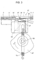
- Fig. 3 is an enlarged front view showing the sealing mechanism.
- An arch type strapping machine 1 comprises a main body 5 in which a band accommodation chamber 3 is formed, an arch member 9 provided on the main body 5 so as to accommodate a band guide 7, a band reel 13 attached to an outer side of the main body 5, on which a band roll (not shown) for a strapping band 11 is mounted, a roller unit 15 disposed in the main body 5 and adapted to feed forward and tighten the strapping band 11, and a sealing mechanism 17 for the strapping band which is disposed in the main body 5 and which cuts and melt-bonds the strapping band 11.
- the strapping band 11 is rewound from the band reel 13 due to the rotation of a feeding/driving roller 19 in a direction of arrow mark A (i.e., a clockwise direction) in the roller unit 15, to be supplied to the band accommodation chamber 3. Then, the strapping band 11 in the band accommodation chamber 3 is fed to the band guide 7 by means of a strapping band driving mechanism 21 in the roller unit 15.
- a pair of winding rollers 23 are provided at front and rear sides of the feeding/driving roller 19.
- the strapping band 11 is fed in a snaky movement between each of the winding rollers 23 and the feeding/driving roller 19, passed on a guide roller 25, and supplied to the band accommodation chamber 3.
- the strapping band driving mechanism 21 comprises a band driving roller 27, a band-running rocker roller 29 disposed at a specified position above the band driving roller 27 to hold the strapping band 11 in association with the band driving roller 27, and a second tightening rocker roller 33 disposed at a specified position below the band driving roller 27 wherein the second tightening rocker roller 33 is moved so as to hold the strapping band 11 in association with the band driving roller 27 when a solenoid plunger for secondarily tightening 31 is operated.
- the strapping band 11, which is extended to the sealing mechanism 17 via the guide roller 25, a guide 35, the band driving roller 27 and the band-running rocker roller 29, is introduced into the band guide 7 through a center guide 37 by the rotation of the band driving roller 27 in a counter clockwise direction (indicated by an arrow mark B) so that a top end of the strapping band 11 is returned to the sealing mechanism 17.
- a proximity switch 39 detects that the top end of the strapping band 11 has reached the position of the sealing mechanism 17, the band feeding step is finished, and the rotation of the band driving roller 27 is stopped.
- a right gripper or a top end gripper 45 (a first gripper) ascended according to a rotating or swinging movement of an L-like lever 43 which is caused by the operation of a solenoid plunger for fixing 41 (a first driving section) and a seal anvil or an iron bed for sealing 47 so that the top end of the strapping band 11 is fixed as shown in Fig. 3 (see Fig. 4 which is a front view showing the structure for operating the right gripper 45. Fig. 4 shows a state that the right gripper 45 descends whereas Fig. 3 shows a state that the right gripper 45 ascends).
- a solenoid plunger 51 for opening the band guide, an operating shaft 53 and a link 55 constitute a first band guide driving unit.
- the center guide 37 is unified with the band guide 7 so as not to cause any deflection in the passage for the band.
- the strapping band 11 is pulled back at a high speed by a high speed rotation of the band driving roller 27 in a clockwise direction (indicated by an arrow mark C) so that the strapping band 11 is wound around an article to be strapped 57 (a first tightening step).
- the band driving roller 27 is rotated at a low speed and a high torque in a clockwise direction, and the second tightening rocker roller 33 is moved in a direction coming to contact with the band driving roller 27 due to the operation of the solenoid plunger for secondary tightening 31 so that the strapping band 11 is strongly held between the second tightening rocker roller 33 and the band driving roller 27.
- a rotating type pulse generator (not shown) is mounted on the band-running rocker roller 29.
- the absence of an output of rotating pulses from the rotating type pulse generator indicates the cease of the rotation of the band-running rocker roller 29. Therefore, the completion of the first tightening step can be confirmed by the detection of the absence of the rotation pulses.
- the sealing mechanism 17 has the right gripper 45, a left gripper or a rear side gripper 61 (a second gripper) and a compression head or a press-cutting head 63.
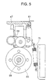
- the left gripper 61 and the compression head 63 are operated by the rotation of a cam for fixing 65 and a cam for bonding 67 which are attached to the shaft for sealing 59 (see Fig. 5 showing the structure for operating the left gripper 61).
- the left gripper 61 Immediately after the initiation of rotation of the shaft for sealing 59 from its neutral position, the left gripper 61 is moved upward by a swing lever 69 pushed upward by a pushing force of the cam for fixing 65, whereby a rear portion of the strapping band 11 is held and fixed between the left gripper 61 and the seal anvil 47.
- An upper end of the left gripper 61 has a rough surface, and a lower surface of the seal anvil 47 corresponding to the left gripper 61 has a flat surface, whereby a possibility of damaging or cutting the strapping band 11 in a case that the rear portion of the strongly stretched strapping band 11 is held and fixed, can be eliminated.
- a heater 71 is disposed at a position in height between the center guide 37 and the seal anvil 47, or a position having a substantially the same level as an upper end of the center guide 37.
- the heater 71 is moved forward to a position between the top end and the rear portion of the strapping band 11.
- the compression head 63 is moved upward by a pushing force of the cam for bonding 67 so as to press the top end of the strapping band 11, the heater 71 and the rear portion of the strapping band 11, in an overlapping state, to the seal anvil 47.
- the compression head 63 cuts a rear portion of the strapping band 11, and at the same time, it melts the top end and the rear portion of the strapping band 11.
- the compression head 63 When the shaft for sealing 59 is rotated further, the compression head 63 is slightly descended along the cam surface of the cam for bonding 67 by a pulling force of a tension coil spring 73, and the heater 71 is retracted to be withdrawn between the top end and the rear portion of the strapping band 11. When the shaft for sealing 59 is rotated further, the compression head 63 is ascended again so that the molten top end and rear portion of the strapping band 11 are pressed and melt-bonded in association with the seal anvil 47.
- the position determining device 77 comprises a disc 78 attached to the shaft for sealing 59 and a swing arm 83 having a roller 79 in contact with the disc 78 at its intermediate portion and an end connected to a supporting shaft 81.
- the swing arm 83 is connected with a tension spring (not shown) which urges the swing arm 83 in such a direction that the roller 79 is pushed to the disc 78.
- the roller 79 is fitted to a recessed portion (not shown) formed in a portion of the disc 78 by a pulling force of the spring, whereby the shaft for sealing 59 can correctly be stopped at the neutral position.
- the article 57 after having been strapped is discharged from the arch type strapping machine 1. Then, an electric current fed to the push type solenoid plunger 49 for opening the band guide and the solenoid plunger 51 for opening the band guide is interrupted, whereby the band guide 7 including the center guide 37 is restored to a state that it is pushed to the arch member 9.
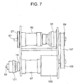
- the band driving roller 27 is attached to an end of the output shaft 87 of a d.c. motor 85.
- An electromagnetic friction clutch 91 with a pulley 89 is provided on the other end of the output shaft 87.
- a tooth clutch 95 having a pulley 93 is provided at a rear end of the shaft for sealing 59 which is rotated by a motor 97.
- the band feeding/driving roller 19 is connected via an electromagnetic clutch 101 to an end of the output shaft 99 of the motor 97 for driving the shaft for sealing.
- a reduction unit 105 having a pulley 103 is provided at the other end of the output shaft 99.
- a single driving belt 107 is wound around the pulley 89, the pulley 93 and the pulley 103.
- the strapping band 11 is driven by a high speed rotation of band driving roller 27 which is caused by a high speed rotation of the d.c. motor 85 in a counterclockwise direction
- the strapping band 11 is driven by a high speed rotation of band driving roller 27 which is caused by a high speed rotation of the d.c. motor 85 in a clockwise direction.
- the electromagnetic friction clutch 91 is connected to the output shaft 87 of the d.c.
- the adjustment of the second tightening force is conducted by changing a voltage applied to the electromagnetic friction clutch 91.
- the tooth clutch 95 is connected to the shaft for sealing 59 so that the shaft for sealing 59 is rotated by the motor 97 for driving the shaft for sealing 59.
- the left gripper 61 is raised to press the strapping band 11.
- the electromagnetic friction clutch 91 is disconnected, and subsequent to this, the compression head 63 is operated.
- the electromagnetic clutch 101 is connected to the output shaft 99 of the motor 97 for driving the shaft for sealing 59 so that the band feeding/driving roller 19 is rotated by a driving force from the motor 97 for driving the shaft for sealing 59, and the strapping band 11 is rewound from the band reel 13 so as to supply the band into the band accommodation chamber 3.
- the heater 71 is attached to a heater supporting member 111 which is attached in a manner capable of sliding to a supporting shaft 81 which is extended in a direction of front and back, i.e., a direction of moving the heater 71 (Fig. 6). Further, the seal anvil 47 is attached to a supporting member 113 which is attached in a manner capable of sliding to the supporting shaft 81 at a front side with respect to the heater supporting member 111 (Fig. 6). A tension coil spring 117 is extended between the heater supporting member 111 and a supporting plate 115 of the arch type strapping machine 1 so that the heater supporting member 111, hence, the heater 71 is always pulled in a front direction.
- the supporting member 113 is attached in a manner capable of sliding to a pressing shaft 119, and a compression coil spring 121 is located between a rear end of the pressing shaft 119 and the supporting member 113, whereby the supporting member 113, hence, the seal anvil 47 is always pushed in a front direction.
- a connecting rod 123 is attached to the heater supporting member 111.
- the connecting rod 123 is inserted in a manner capable of sliding in a hole formed in the supporting member 113, and has a head for pulling 125 at its top end.
- the heater supporting member 111 is adapted to move in a direction of front and back along a cam surface which is formed at a rear end of a cylindrical cam 127 attached to the shaft for sealing 59.
- FIG. 8 shows a state before the initiation of rotation of the shaft for sealing wherein the seal anvil 47 is advanced and the heater 71 is retracted.
- the left gripper 61 is raised, and subsequent to this, the heater supporting member 111 is moved in a front direction along the cam surface of the cylindrical cam 127 by a pulling force of the tension coil spring 117, and then, the heater 71 is moved between the rear portion and the top end of the strapping band 11.
- the seal anvil 47 is prohibited to move forward beyond the position as indicated in Fig. 8.
- the heater supporting member 111 When the shaft for sealing 59 is rotated further, the heater supporting member 111 is moved in a rear direction by the cam surface of the cylindrical cam 127, whereby the heater 71 is also retracted. However, the seal anvil 47 is remained at the advanced position.
- the heater supporting member 111 When the heater supporting member 111 is retracted further by the pushing force of the cam surface of the cylindrical cam 127 with the rotation of the shaft for sealing 59, the supporting member 113 is moved in a rear direction by a pulling force of the connecting rod 123, and therefore, the seal anvil 47 is moved backward.
- the cylindrical cam 127 has also a cam surface at its front end, which as soon as the initiation of the rotation of the shaft for sealing 59, operates a vertically extending portion 129 of the L-like lever 43 to maintain the right gripper 45 at an elevated position (see Fig. 4), whereby an electric current to the solenoid plunger for fixing 41 is interrupted.
- the L-like lever 43 is rotated in a direction of raising along the cam surface formed at the front end of the cylindrical cam 127 by a pushing force of a spring 131 to return to the original position, and the right gripper 45 is lowered.
- the first driving section and the second driving section are respectively constructed so as to operate separately.
- the right gripper is operated by the first driving section, and then, the second driving section is operated.
- the second driving section comprises the motor for sealing, the shaft for sealing, and the cam for fixing and the cam for bonding which are attached to the shaft for sealing.
- the left gripper and the compression head are operated sequentially by the continuous rotation of 360° of the shaft for sealing which is caused by the motor for sealing.
- the source for driving the first driving section is generally separate from the motor for sealing as the source for driving the second driving section.
- the right gripper is not always necessary to be operated by the first driving section.
- the first driving section is to cause an initial operation of the right gripper.
- Another driving section may be provided to maintain the initial operation and may perform the subsequent operations for the right gripper.
- a cam is usually provided on the shaft for sealing so that the band guide is opened by the rotation of the shaft for sealing.
- the band guide has to be maintained in an opening state at least until the completion of the strapping band pulling step. Accordingly, it is necessary for the above-mentioned structure to stop once the shaft after the rotation of the shaft for sealing, and then, to rotate again the shaft. Therefore, in order to open forcibly the band guide, another driving section for the band guide may be provided separate from the second driving section.
- a solenoid plunger may be used for the first driving section and the driving section for the band guide.
- the band driving roller is driven by the motor in order to perform directly the band feeding step, the first tightening step and the second tightening step.
- the strapping band In order to reduce the size of the arch type strapping machine, it is preferred to feed the strapping band into the band accommodation chamber by providing a band feeding/driving roller on one side of the output shaft of a motor via an electromagnetic clutch and providing a reduction unit on the other side of the output shaft wherein the band feeding/driving roller is rotated by the connection of the electromagnetic clutch, and to conduct the second tightening step by the rotation of the band driving roller due to a rotating force from the reduction unit. Further, it is effective to use the above-mentioned motor to operate the sealing mechanism (including a part of the sealing mechanism) for cutting a rear portion of the strapping band wound around an article to be strapped, and then, bond (or melt-bond) the rear portion to the top end of the strapping band. In many cases, the motor is to rotate the shaft for sealing to which a driving cam is attached. Or, the motor for driving the sealing mechanism may be used for a source for conducting the second tightening step so that an output of rotation of the motor is transmitted to the band
- Fig. 9 shows diagrammatically a band guide 7 of the arch type strapping machine 1 provided with band driving-out devices 239 for a strapping band according to the present invention
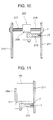
- Fig. 10 is a plan view partly cross-sectioned showing an upper supporting device in detail
- Fig. 11 is a plan view partly cross-sectioned showing a pushing type solenoid plunger for opening the band guide.
- the band guide 7 having a channel-like shape in cross section is arranged in a loop form along the arch member 9 of the arch type strapping machine 1, and an upper central portion of the band guide 7 is supported by the upper supporting device 207.
- the upper supporting device 207 comprises a movable supporting member 209 located at an upper central portion of the band guide 7, a guide rod 215 attached to a first arch plate 211 (a front side arch plate) of the arch member 9 and a second arch plate 213 (a rear side arch plate) of the arch member 9 in its upper portion to extend horizontally or in parallel to a front/rear direction, i.e., in a width direction of the band guide 7 and to support the movable supporting member 209 in a manner capable of sliding, and a compression coil spring 217 wound on the guide rod 215 between the second arch plate 213 and the movable supporting member 209.
- the band guide 7 is in such a state that a side of the opening of a groove 219 of the channel-like band guide 7 is pressed to the first arch plate 211 by a spring action of the compression coil spring 217.
- the strapping band 11 is movable in the groove 219.
- the movable supporting member 209 is urged together with the band guide 7 in a rear direction, i.e., the band guide 7 being moved in a direction aparting from the first arch plate 211, along the guide rod 215 against the spring action of the compression coil spring 217.
- the groove 219 is preferably formed to be thin. Accordingly, a lower wall of the band guide 7 in Fig. 10 on which the band slips, is formed to be slightly thin so that the withdrawal of the band 11 can be smooth even when the band drags on the inner surface of the groove 219.
- Pushing type solenoid plungers 49 for opening the band guide are fixed to the first arch plate 211 at the second and third corner portions of the arch member 9 respectively.
- An operating portion 49a of each of the pushing type solenoid plungers 49 is attached to the band guide 7.
- a pair of return spring members 227 are provided at both sides of the band guide 7.
- Each of the return spring members 227 is constituted by a stick 229 and a tension coil spring 231 connected to a lower end of the stick 229 wherein an upper end of the stick 229 is attached to the first arch plate 211 in a rotatable manner, and a lower end of the tension coil spring 231 is attached to an outer side of the band guide 7.
- the operating shaft 53 is disposed in a rotatable manner along a lower portion of the band guide 7.
- the operating shaft 53 and the lower portion of the band guide 7 are connected by means of the link 55.
- An end portion of the operating shaft 53 is connected to the solenoid plunger 51 for opening the band guide 7.
- the solenoid plunger 51 By the operation of the solenoid plunger 51, the operating shaft 53 is rotated to open the band guide 7 via the link 55.
- the lower portion of the band guide 7 is pushed by a spring (not shown) toward the first arch plate 211.
- the band guide 7 is moved in its entirety to perform an opening operation in a direction aparting from the first arch plate 211.
- the arch member 9 is provided with a pair of band driving-out devices 239 each of which prevents the strapping band 11 from following the movement of the band guide 7 and remaining in the groove 219 of the band guide 7 when the band guide 7 is subjected to the opening operation.
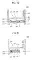
- Fig. 12 is a plan view partly cross-sectioned of a band driving-out device in detail wherein a state before the opening of the band guide 7 is shown, and Fig. 13 shows a state after the opening of the band guide 7.
- Each of the band driving-out devices 239 is provided at lower corner portions of the arch member 9, and comprises a pin stopper 241 made of a metallic plate, a push pin 245 having a head portion 243 at its rear end and a compression coil spring 247.
- the pin stopper 241 has an integral body comprising a fixing portion 249 fixed to the first arch plate 211, a portion 251 having a larger width than the band guide 7, which extends from an end of the fixing portion 249 in a rear direction, i.e., in a width direction of the band guide 7 and a rear portion 255 which is contiguous to the other end (a rear end) of the portion 251 and which extends in parallel to the arch member 9 or the first and second arch plates 211, 213 to a position behind a rear portion 253 of the band guide 7.
- a through hole 257 is formed penetrating the rear portion 253 of the band guide 7 to reach the groove 219.
- the push pin 254 is inserted in the through hole 257 from its top end side in a manner capable of sliding.
- the compression coil spring 247 is fitted to the push pin 245 so as to be interposed between a rear surface of the band guide 7 and the head portion 243 of the push pin 245, whereby the head portion 243 of the push pin 245 is always pressed toward the rear portion 255 of the pin stopper 241 to be in contact with the rear portion 255.
- the band guide 7 Before the opening operation of the band guide 7, the band guide 7 is pressed to the first arch plate 211 by the compression coil spring 247, and the top end of the push pin 245 is around the top end side of the through hole 257 so as not to enter into the groove 219.
- the top end of the push pin 245 enters into the groove 219 and is advanced relatively to the position of the opening of the groove 219 in a state that the band guide 7 is fully opened. Accordingly, the strapping band 11 is driven out from the groove 219 by means of the push pin 245 even when the band 11 tends to follow the movement of the band guide 7.
- the strapping band is in a state of being drawn entirely from the band guide 7 in the completion of the opening operation of the band guide 7.
- the through hole is formed to penetrate the rear surface of the band guide to reach the groove.
- the band guide When the band guide is operated to be opened by the spring action in a direction aparting from the inner surface of the first arch plate, i.e., in a direction that the opening of the groove is apart from the inner surface of the first arch plate in a state that the strapping band is supplied into the groove of the band guide, the top end of the push pin enters deeply into the groove so that the strapping band or a band portion which tends to follow the movement of the band guide, is driven out from the groove.
- the push pin is merely brought into contact with the pin stopper, namely, the push pin is capable of sliding with respect to the pin stopper, there is little possibility of causing a trouble in the opening operation of the band guide even when the band guide shakes in the opening operation to increase a frictional force between the push pin and the band guide.
- the spring member in the band driving-out devices functions to bring the push pin into contact with the pin stopper when the band guide is returned to the original position. Further, this spring member provides generally a returning force or a substantial auxiliary returning force to the band guide. Usually, the spring member acts on the band guide to provide a pushing force or an auxiliary pushing force against the inner surface of the first arch plate. It is preferable that the spring force of the spring member is such an extent that a contact pressure between the head portion of the push pin and the pin stopper is not too excessive, and the push pin can smoothly slide toward the pin stopper when the band guide is operated for opening.
- the band driving-out devices of the present invention are preferably located at such positions that the strapping band can follow a forcibly opening operation of the band guide, for example, at corner portions of the arch member or the band guide.
- the pin stopper may be such one fixed to the arch member.
- the arch plate at the opposite side of the arch plate to which the band guide is pressed can be used as it is.
- Fig. 14 is a vertically cross-sectional view showing the entire structure of a band reel 13 for a strapping band
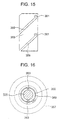
- Fig. 15 is a diagram in a developed state of a portion in which guide grooves are formed in a cylindrical portion of a nob, wherein the shape of the guide grooves is shown
- Fig. 16 is a cross-sectional view showing a state of engagement of pins of a supporting shaft.
- a top end portion of a supporting shaft 325 (a side of the main body 5 of the strapping machine 1 is referred to as a top end side or a front side, and the opposite side thereof, i.e., a free end side is referred to as a rear end side or a rear side) which supports a band reel 13, is provided with a bearing 327 which is fixed to the main body of the arch type strapping machine 1.
- the top end portion of the supporting shaft 325, which extends beyond the bearing 327 into the main body 5 is fixed with a pulley 329 which is connected to an electromagnetic brake (not shown) by means of belt 331.
- a collar 333 is fixed to a rear side of the supporting shaft 325 with respect to the bearing 327.
- the main body 337 of a reel portion 335 is connected to the collar 333.
- the main body 337 comprises a side plate 339 (a front side plate) made of a thin metallic plate in which a fitting hole is formed at the center and an annular body portion 343 made of a thin metallic plate.
- the annular body portion 343 has, at its an end (front end), a bottom portion 341 having a fitting hole at its center, fixed to the side plate 339 and at its other side (a rear side), an opening having a smaller diameter than the fitting hole of the side plate 339.
- a cylindrical portion 345 of the collar 333 is inserted into the fitting hole of the side plate 339 and the fitting hole of the bottom portion 341.
- the side plate 339 and the bottom portion 341 are fixed to a flange portion 347 of the collar 333.
- the main body 337 of the reel portion 335 is attached fixedly to the collar 333, i.e., the supporting shaft 325.
- the reel portion 335 is adapted to fit a band roll 317, in which the strapping band 11 is wound around a core member 349, to an outer circumference of the annular body portion 343 and to attach the side plate 339 and the other side plate 351 (a rear side plate) to the supporting shaft 325 so that the strapping band 11 is held between both the side plates 339, 351.
- the rear side plate 351 is assembled to the nob 353 (or a cap). Namely, the rear side plate 351 is attached to the supporting shaft 325 by fixing the nob 353 to the supporting shaft 325.
- the nob 353 comprises a cylindrical portion 355 to which a rear end portion of the supporting shaft 325 can be fitted and a handle portion 357 fixed to a rear end of the cylindrical portion 355.
- the rear side plate 351 is assembled to the nob 353 by inserting the cylindrical portion 355 into a fitting hole formed at the center of the rear side plate 351.
- two guide grooves 359 extending spirally from its front end portion to the rear portion at a distance of 180° wherein a recess 361 recessed in a front direction (or extending slightly in a front direction) is formed at a rear end of each of the guide grooves 359.
- Two pins 363 are also formed in a rear portion of the supporting shaft 325 at a distance of 180° so as to correspond to the guide grooves 359.
- the height of the pins 363 is slightly lower than the thickness of the cylindrical portion 355.
- An annular groove 365 is formed in a rear side surface of the handle portion 357 of the nob 353, and a head portion of a compression coil spring 367 having a truncated cone shape is fitted to the annular groove 365 so that the rear side plate 351 is pressed toward the band roll 317 whereby the band roll 317 is held between the both side plates 339, 351.
- reference numeral 369 designates a C-ring which prevents the rear side plate 351 from coming off.
- each opening formed at the top end of the guide grooves 359 of the nob 353 is made coincident with each of the pins 363 of the supporting shaft 325 (Fig. 16 shows such state), and the nob 353 is pushed to the shaft. Then, the nob 353 is moved forwardly while rotating around its own axis whereby it can be fitted to the supporting shaft 325. When the pins 363 reach the rear end portion of the guide grooves 359, the rotation and the advance of the nob 353 are stopped.
- the band roll 317 comes to contact with the outer circumference and so on of the rear side plate 351, and the compression coil spring 367 is compressed between the rear side plate 351 and the nob 353 at the time of the completion of pushing the nob 353. Accordingly, when the pushing force to the nob 353 is removed, the nob 353 is moved in a direction of coming-off from the supporting shaft 325 (i.e., a rear direction) by the spring action of the compression coil spring 367 compressed between the nob 353 and the rear side plate 351. As a result, the pins 363 are fitted to the recesses 361 so that the nob 353 is engaged with the supporting shaft 325 so as not to cause the rotation.
- the nob 353 When the nob 353 is to be removed from the supporting shaft 325, the nob 353 should be pushed against the spring action of the compression coil spring 367 to disengage the pins 363 from the recesses 361, and the nob 353 is pulled while rotated slightly. Thus, the nob 353 can be disengaged from the supporting shaft 325 under the rotation.
- the nob can be fitted to the supporting shaft by making the openings of guide groove coincident with the pins and pushing the nob, whereby the nob is advanced according to the relative movement and rotation of the pins with respect to the guide grooves.
- the pins reach the rear end (i.e., inlets of recess) of the guide grooves, the movement of the nob is stopped.
- the nob is moved in a rear direction by weakening the pushing force to the nob since the nob is urged in a rear direction (a direction capable of coming-off from the supporting shaft) by the spring member disposed between the nob and the reel portion.
- the pins are fitted to the recesses whereby the nob can be fixed to the supporting shaft in a non-rotatable manner.
- the rear side plate of the reel portion is attached to the nob (in many cases, the side plate is assembled to the cylindrical portion of the nob). Then, the assembling or disassembling of the side plate can be conducted together with the removal or the attachment of the nob.
- one continuous revolution of the shaft for sealing having a cam for driving can be performed without stopping it. Accordingly, the steps of cutting and melt-bonding of the strapping band can be conducted quickly.
- the band feeding step, the first and second tightening steps can be performed by only the rotation and driving of the band driving roller. Accordingly, the size of the strapping machine can be reduced.
- the remaining of the strapping band in the groove of the band guide at the time of opening the band guide can be prevented.
- the push pin can follow the movement of the band guide even when the band guide shakes at the time of opening of the band guide. Accordingly, a smooth opening operation of the band guide can be maintained.
- the replacement of band rolls can quickly and simply be conducted.
Landscapes
- Engineering & Computer Science (AREA)
- Mechanical Engineering (AREA)
- Basic Packing Technique (AREA)
Claims (12)
- Verschnürungsmaschine (1) mit bogenförmigem Bandführungskanal und einem Verklebungsmechanismus (17), welcher umfasst:das Antriebsmittel des Verklebungsmechanismus eine erste Antriebssektion (41, 43) zum Betätigen der rechten Greifeinrichtung und eine zweite Antriebssektion (97, 59, 65, 67) zum Betätigen der linken Greifeinrichtung und des Kompressionskopfes aufweist, wobei die zweite Antriebssektion einen Motor (97) zum Verkleben, eine vom Motor gedrehte Welle (59) zum Verkleben, einen an der Welle zum Verkleben angebrachten Fixiernocken (65), um die linke Greifeinrichtung zu betätigen, und einen Nocken (67) zum Verbinden aufweist, um den Kompressionskopf zu betätigen.(a) eine rechte Greifeinrichtung (45), um ein Kopfende eines in eine Bandführung (7) der Verschnürungsmaschine mit bogenförmigem Bandführungskanal zugeführten Verschnürungsbandes (11) zu fixieren;(b) eine linke Greifeinrichtung (61), um einen hinteren Teil des Verschnürungsbandes zu fixieren, nachdem das Verschnürungsband um einen zu verschnürenden Gegenstand (57) gewickelt und festgezogen wurde;(c) einen Kompressionskopf (63), um das Kopfende und den hinteren Teil des Verschnürungsbandes zusammenzudrücken und zu verbinden und den hinteren Teil des Bandes abzuschneiden, und(d) ein Antriebsmittel (41, 43, 59, 65, 67), um die rechte Greifeinrichtung (45), die linke Greifeinrichtung (61) und den Kompressionskopf (63) zu betätigen, wobei die Verschnürungsmaschine mit bogenförmigem Bandführungskanal dadurch gekennzeichnet ist, dass :
- Verschnürungsmaschine mit bogenförmigem Bandführungskanal nach Anspruch 1, worin der Verklebungsmechanismus (17) eine die Bandführung antreibende Sektion (51) aufweist, die separat von der zweiten Antriebssektion (97, 59, 65, 67) betätigt wird und die Bandführung (7) zwangsweise öffnet.
- Verschnürungsmaschine mit bogenförmigem Bandführungskanal nach Anspruch 1 oder 2, worin die erste Antriebssektion (41, 45) einen Solenoid-Plungerkolben (41) zum Betätigen der rechten Greifeinrichtung (45) aufweist.
- Verschnürungsmaschine mit bogenförmigem Bandführungskanal nach Anspruch 2, worin die die Bandführung antreibende Sektion (51) einen Solenoid-Plungerkolben (51) zum Öffnen der Bandführung aufweist.
- Verschnürungsmaschine mit bogenförmigem Bandführungskanal nach einem der Ansprüche 1 bis 4, mit einem Verschnürungsbänder antreibenden Mechanismus, der einen Bandzufuhrschritt zum Zuführen eines Verschnürungsbandes in eine Bandführung der Verschnürungsmaschine mit bogenförmigem Bandführungskanal ausführt, einen ersten Festziehschritt zum Wickeln des Verschnürungsbandes um einen zu verschnürenden Gegenstand, indem das in die Bandführung zugeführte Verschnürungsband schnell zurückgeführt wird, und einen zweiten Festziehschritt, um das um den Gegenstand gewickelte Verschnürungsband straff festzuziehen, indem das Verschnürungsband zurückgezogen wird, wobei die Verschnürungsmaschine mit bogenförmigem Bandführungskanal dadurch gekennzeichnet ist, dass:der Verschnürungsbänder antreibende Mechanismus einen Gleichstrommotor (85) aufweist, der in einer positiven Zufuhrrichtung und in einer umgekehrten Rückführrichtung rotieren kann; eine Bandantriebsrolle (27), die an einem Ende einer Ausgangswelle (87) für einen Bandlauf des Gleichstrommotors angebracht ist, und einen Motor (97) zum Antreiben der Welle zum Verkleben, verbunden mit der Ausgangswelle über eine elektromagnetische Kupplung (91), die am anderen Ende der Ausgangswelle des Gleichstrommotors (85) angebracht ist, wobei der Bandzufuhrschritt durch die Rotation der Bandantriebsrolle ausgeführt wird, die durch die Rotation in einer Zufuhrrichtung des Gleichstrommotors bewirkt wird, der erste Festziehschritt durch die Rotation der Bandantriebsrolle ausgeführt wird, die durch die Rotation in einer Rückführrichtung des Gleichstrommotors bewirkt wird, und der zweite Festziehschritt durch die Rotation der Bandantriebsrolle durchgeführt wird, die durch einen Rotationsabtrieb vom Motor zum Antreiben der Welle zum Verkleben über die elektromagnetische Kupplung bewirkt wird.
- Verschnürungsmaschine mit bogenförmigem Bandführungskanal nach Anspruch 5, worin eine Bandzufuhr/Antriebsrolle (19) an einem Ende einer Ausgangswelle (99) zum Festziehen des Motors (97) angebracht ist, um die Welle zum Verkleben über eine elektromagnetische Kupplung (101) anzutreiben, und ein Untersetzungsgetriebe (105) am anderen Ende der Ausgangswelle zum Festziehen vorgesehen ist, wodurch das Verschnürungsband durch die Rotation der Bandzufuhr/Antriebsrolle (19) unter der Kopplung der elektromagnetischen Kupplung (101) einer Bandaufnahmekammer (3) zugeführt wird und der zweite Festziehschritt durch die Rotation der Bandantriebsrolle (27) aufgrund eines Rotationsabtriebs vom Untersetzungsgetriebe durchgeführt wird.
- Verschnürungsmaschine mit bogenförmigem Bandführungskanal nach Anspruch 5 oder 6, worin der Motor (97) zum Antreiben der Welle zum Verkleben einen hinteren Teil des um einen zu verschnürenden Gegenstand (57) gewickelten Verschnürungsbandes abschneidet und den Verklebungsmechanismus (17) zum Verbinden eines Kopfendes und des hinteren Teils des Verschnürungsbandes antreibt.
- Verschnürungsmaschine nach einem der vorhergehenden Ansprüche, mit einer Bandaustriebseinrichtung (239), die dafür eingerichtet ist, ein Verschnürungsband (11) aus einer Bandführung (7) austreten zu lassen, wenn die in einem Bogenelement (9) der Verschnürungsmaschine mit bogenförmigem Bandführungskanal angeordnete Bandführung geöffnet wird, wodurch verhindert wird, dass das Verschnürungsband in einer Bandrille (219) verbleibt, wobei die Verschnürungsmaschine mit bogenförmigem Bandführungskanal dadurch gekennzeichnet ist, dass die Bandaustriebseinrichtung einen Schubbolzen (245) aufweist, der in ein Durchgangsloch (257) beweglich eingesetzt ist, das in einem hinteren Teil das Bandführung (7) ausgebildet ist, einen Bolzenanschlag (241), der so angeordnet ist, dass er einem Kopfteil (243) des Schubbolzens gegenüberliegt, und ein Federelement (247), das zwischen dem hinteren Teil der Bandführung und dem Kopfteil des Schubbolzens angeordnet ist, um den Kopfteil des Schubbolzens so zu schieben, dass er mit dem Bolzenanschlag in Kontakt gebracht wird.
- Verschnürungsmaschine mit bogenförmigem Bandführungskanal nach Anspruch 8, worin das Federelement (247) der Bandaustriebseinrichtung (239) eine am Schubbolzen befestigte gewundene Druckfeder ist.
- Verschnürungsmaschine mit bogenförmigem Bandführungskanal nach einem der vorhergehenden Ansprüche mit einer Bandspule (13) für ein Verschnürungsband, wobei die Verschnürungsmaschine mit bogenförmigem Bandführungskanal dadurch gekennzeichnet ist, dass die Bandspule (13) für ein Verschnürungsband eine Tragwelle (325) mit einem durch den Hauptkörper (5) der Verschnürungsmaschine abgestützten Ende, einen an der Tragwelle angebrachten Spulenteil (335), der dafür eingerichtet ist, eine Bandrolle (317) zu montieren, auf der ein Verschnürungsband (11) gewickelt ist, das einer Bandführung in einem Bogenelement der Verschnürungsmaschine mit bogenförmigem Bandführungskanal zugeführt wird, und einen Knopf (engl. nob) (353) aufweist, der an einem hinteren Ende der Tragwelle angebracht ist, um den Spulenteil zu fixieren, wobei der Knopf einen zylindrischen Teil (355) hat, der an einem äußeren Umfang des hinteren Endes der Tragwelle befestigt ist; der zylindrische Teil mit einer Führungsrille (359) versehen ist, die von seiner Vorderseite spiralförmig zu seiner Rückseite verläuft; eine Aussparung (361) im innersten Teil der Führungsrille ausgebildet ist, und ein Bolzen (363), der die Führungsrille relativ passieren kann, so daß er sich in die Aussparung einfügt, in einem hinteren Endteil der Tragwelle (325) vorgesehen ist.
- Verschnürungsmaschine mit bogenförmigem Bandführungskanal nach Anspruch 10, worin zwischen dem Knopf und dem Spulenteil (335) ein Federelement (367), um den Knopf (353) zu einer Seite zu schieben, angeordnet ist.
- Verschnürungsmaschine mit bogenförmigem Bandführungskanal nach Anspruch 10 oder 11, worin zwei Führungsrillen (359) und zwei Aussparungen (361) im zylindrischen Teil (355) des Knopfes ausgebildet sind und zwei Bolzen (363) im hinteren Endteil der Tragwelle (325) an den beiden Rillen (359) entsprechenden Positionen vorgesehen sind.
Applications Claiming Priority (8)
| Application Number | Priority Date | Filing Date | Title |
|---|---|---|---|
| JP2001110234A JP4698872B2 (ja) | 2001-04-09 | 2001-04-09 | 梱包用バンドの残留防止装置 |
| JP2001110233 | 2001-04-09 | ||
| JP2001110233A JP4688334B2 (ja) | 2001-04-09 | 2001-04-09 | 梱包用バンドリール |
| JP2001110234 | 2001-04-09 | ||
| JP2001112059 | 2001-04-10 | ||
| JP2001112060A JP4718709B2 (ja) | 2001-04-10 | 2001-04-10 | 梱包用のバンドの駆動装置 |
| JP2001112059A JP4688336B2 (ja) | 2001-04-10 | 2001-04-10 | 梱包用バンドのシール装置 |
| JP2001112060 | 2001-04-10 |
Publications (3)
| Publication Number | Publication Date |
|---|---|
| EP1249397A2 EP1249397A2 (de) | 2002-10-16 |
| EP1249397A3 EP1249397A3 (de) | 2003-01-02 |
| EP1249397B1 true EP1249397B1 (de) | 2005-01-19 |
Family
ID=27482190
Family Applications (1)
| Application Number | Title | Priority Date | Filing Date |
|---|---|---|---|
| EP01125171A Expired - Lifetime EP1249397B1 (de) | 2001-04-09 | 2001-10-23 | Verschnürungsmaschine mit Bandführungskanal |
Country Status (3)
| Country | Link |
|---|---|
| US (1) | US6655117B2 (de) |
| EP (1) | EP1249397B1 (de) |
| DE (1) | DE60108476T2 (de) |
Cited By (1)
| Publication number | Priority date | Publication date | Assignee | Title |
|---|---|---|---|---|
| US8327758B2 (en) | 2006-08-15 | 2012-12-11 | Maschinenfabrik Gerd Mosca Ag | Tape strapping machine |
Families Citing this family (30)
| Publication number | Priority date | Publication date | Assignee | Title |
|---|---|---|---|---|
| US7315848B2 (en) * | 2001-12-12 | 2008-01-01 | Aaron Pearse | Web snippets capture, storage and retrieval system and method |
| DE10218135B4 (de) * | 2002-04-23 | 2006-07-27 | Titan Umreifungstechnik Gmbh & Co Kg | Vorrichtung zum Umreifen von Warenstücken mit Band |
| SE522986C2 (sv) | 2002-07-09 | 2004-03-23 | Metso Paper Inc | Bindningsanordning |
| JP4212852B2 (ja) * | 2002-08-06 | 2009-01-21 | グローリー株式会社 | 金種別カラー印刷可能な結束テープによる紙幣結束処理機 |
| JP2004142830A (ja) * | 2002-09-30 | 2004-05-20 | Strapack Corp | バンド掛け梱包機 |
| JP2004123157A (ja) * | 2002-10-01 | 2004-04-22 | Strapack Corp | バンド掛け梱包機におけるバンドリフィード方法 |
| US7121194B2 (en) * | 2002-11-27 | 2006-10-17 | Illinois Tool Works, Inc. | Strapping machine having improved winder assembly |
| US6912950B2 (en) * | 2002-11-27 | 2005-07-05 | Illinois Tool Works, Inc. | Strapping machine with improved chute release system |
| US6951170B2 (en) * | 2003-06-17 | 2005-10-04 | Illinois Tool Works, Inc. | Strapping machine with improved chute release system |
| US6962109B2 (en) * | 2003-06-17 | 2005-11-08 | Illinois Tool Works, Inc. | Strapping machine with automatic chute opening system |
| US6981353B2 (en) * | 2003-06-20 | 2006-01-03 | Illinois Tool Works, Inc. | Strapping machine with strap feeding and tensioning system with automatic refeed |
| US6820402B1 (en) * | 2003-06-20 | 2004-11-23 | Illinois Tool Works, Inc. | Strapping machine with pivoting dispenser loading |
| ITMI20031261A1 (it) * | 2003-06-20 | 2004-12-21 | Messersi Packaging Srl | Macchina reggiatrice con gruppo perfezionato di movimentazione della reggia. |
| ES2249990B1 (es) | 2004-08-03 | 2007-08-01 | Indo Internacional S.A. | Herramienta y procedimiento para pulir superficies opticas. |
| US7287717B2 (en) * | 2005-02-04 | 2007-10-30 | Illinois Tool Works, Inc. | Strap dispenser with start assist |
| US7165379B1 (en) * | 2005-07-25 | 2007-01-23 | Tony Lai | Forward-reverse tension mechanism for packing machine |
| CH698112B1 (de) * | 2005-09-05 | 2009-05-29 | Ats Tanner Banding Systems Ag | Banderolieren eines Packgutstapels. |
| US7454877B2 (en) * | 2006-09-26 | 2008-11-25 | Illinois Tool Works Inc. | Tension control system and method for tensioning a strapping material around a load in a strapping machine |
| PT2125527E (pt) | 2007-02-23 | 2012-08-30 | Int Enterprises Inc | Aparelho e método para aplicar uma cinta em torno de um feixe de objetos |
| US7798060B2 (en) * | 2007-10-24 | 2010-09-21 | Illinois Tool Works Inc. | Modular strap dispenser with feed motor |
| US7377212B1 (en) * | 2007-11-20 | 2008-05-27 | Jangzin Industrial Co., Ltd. | Automatic band conveying device |
| DE102008004118B4 (de) * | 2008-01-11 | 2011-04-14 | Maschinenfabrik Gerd Mosca Ag | Umreifungsmaschine mit einem Bandführungskanal und einer Zufuhreinheit |
| US8336801B2 (en) * | 2009-06-08 | 2012-12-25 | Illinois Tool Works Inc. | Anti-rotation system for strap dispenser outer flange |
| DE102010016774B4 (de) * | 2010-05-04 | 2012-03-29 | Cyklop Gmbh | Vorrichtung zum Umreifen von Packstücken mit Umreifungsband |
| CN102530291B (zh) * | 2011-12-22 | 2013-07-10 | 杭州永创智能设备股份有限公司 | 一种新型打包机 |
| EP3915886A1 (de) * | 2020-05-28 | 2021-12-01 | ATS-Tanner Banding Systems AG | Anpassbare banderoliermaschine |
| CN112027238B (zh) * | 2020-10-16 | 2022-02-22 | 东莞市榕盛包装科技有限公司 | 一种捆扎打包机 |
| DE102021125067B4 (de) * | 2021-09-28 | 2023-08-03 | Mosca Gmbh | Ausstoßer für eine Umreifungsmaschine |
| CN117902096B (zh) * | 2024-02-05 | 2025-09-26 | 珠海博杰电子股份有限公司 | 打包机穿剑装置 |
| CN121134102B (zh) * | 2025-11-18 | 2026-03-06 | 云南铝业股份有限公司 | 一种铝锭打捆设备及方法 |
Family Cites Families (24)
| Publication number | Priority date | Publication date | Assignee | Title |
|---|---|---|---|---|
| US3196779A (en) * | 1961-08-28 | 1965-07-27 | Ovalstrapping Ltd | Automatic strapping machine |
| CH574841A5 (de) * | 1974-12-20 | 1976-04-30 | Strapex Ag | |
| NL7502765A (nl) * | 1975-03-07 | 1976-09-09 | Metaverpa Nv | Inrichting voor het aanbrengen van een uit kunst- stof bestaande band om een pakket of dergelijke. |
| JPS53102199A (en) * | 1977-02-17 | 1978-09-06 | Nichiro Kogyo Kk | Method for packing by way of thermoplastic band |
| JPS6077820A (ja) * | 1983-10-03 | 1985-05-02 | ニチロ工業株式会社 | バンド式梱包機のバンド引戻し引締め装置 |
| US4724659A (en) * | 1985-12-24 | 1988-02-16 | Nichiro Kogyo Company Ltd. | Band type strapping machine |
| JPH0312642Y2 (de) * | 1987-10-12 | 1991-03-25 | ||
| JP2740804B2 (ja) * | 1990-02-09 | 1998-04-15 | ストラパック株式会社 | 梱包機における空梱包バンドの除去方法 |
| DE4014307C2 (de) * | 1990-05-04 | 1996-11-07 | Rmo Systempack Gmbh | Packmaschine |
| US5249518A (en) * | 1992-10-02 | 1993-10-05 | Signode Corporation | Stripping mechanism for strapping machine |
| JP2905346B2 (ja) * | 1992-11-05 | 1999-06-14 | ストラパック株式会社 | 梱包機におけるバンド案内アーチ |
| JPH0740921A (ja) * | 1993-07-20 | 1995-02-10 | Kioritz Corp | 梱包機 |
| JPH0740917A (ja) * | 1993-07-21 | 1995-02-10 | Kioritz Corp | 梱包機 |
| JP3227061B2 (ja) * | 1994-07-18 | 2001-11-12 | 株式会社共立 | 梱包機 |
| TW291470B (de) * | 1995-02-14 | 1996-11-21 | Nichiro Kogyo Kk | |
| US5809873A (en) * | 1996-11-18 | 1998-09-22 | Ovalstrapping, Inc. | Strapping machine having primary and secondary tensioning units and a control system therefor |
| DE29722491U1 (de) * | 1997-12-19 | 1998-02-19 | Cyklop GmbH, 50996 Köln | Vorrichtung zum Verschweißen und Abschneiden eines Umreifungsbandes |
| US5942061A (en) * | 1998-04-03 | 1999-08-24 | Illinois Tool Works Inc. | Cam operated strap welding tool and method therefor |
| US6073425A (en) * | 1999-05-24 | 2000-06-13 | Tekpak Corporation | Guide frame of lashing tape of binding machine |
| JP2001112059A (ja) | 1999-10-08 | 2001-04-20 | Hitachi Ltd | 通信方式および通信装置 |
| JP3440220B2 (ja) | 1999-10-08 | 2003-08-25 | 日本電信電話株式会社 | 通信端末および通信方法 |
| JP4073126B2 (ja) | 1999-10-13 | 2008-04-09 | 株式会社荏原製作所 | 導電接着剤 |
| JP2001110233A (ja) | 1999-10-14 | 2001-04-20 | Tdk Corp | 内部電極形成用の導電体ペースト並びに積層セラミック電子部品 |
| US6415712B1 (en) * | 1999-12-02 | 2002-07-09 | Enterprises International, Inc. | Track mechansim for guiding flexible straps around bundles of objects |
-
2001
- 2001-10-23 EP EP01125171A patent/EP1249397B1/de not_active Expired - Lifetime
- 2001-10-23 DE DE60108476T patent/DE60108476T2/de not_active Expired - Lifetime
- 2001-10-24 US US09/983,301 patent/US6655117B2/en not_active Expired - Lifetime
Cited By (1)
| Publication number | Priority date | Publication date | Assignee | Title |
|---|---|---|---|---|
| US8327758B2 (en) | 2006-08-15 | 2012-12-11 | Maschinenfabrik Gerd Mosca Ag | Tape strapping machine |
Also Published As
| Publication number | Publication date |
|---|---|
| EP1249397A3 (de) | 2003-01-02 |
| US6655117B2 (en) | 2003-12-02 |
| DE60108476T2 (de) | 2006-03-23 |
| DE60108476D1 (de) | 2005-02-24 |
| EP1249397A2 (de) | 2002-10-16 |
| US20020144489A1 (en) | 2002-10-10 |
Similar Documents
| Publication | Publication Date | Title |
|---|---|---|
| EP1249397B1 (de) | Verschnürungsmaschine mit Bandführungskanal | |
| US7380574B2 (en) | Wire strapper for waste material baler | |
| JP4663907B2 (ja) | 巻上げ機および束縛装置 | |
| US20040200191A1 (en) | Apparatus and methods for applying a strap around a bundle of objects | |
| EP2094569B1 (de) | Umreifungsmaschine mit zentrifugalem antriebsrad | |
| JP2004091016A (ja) | 自動バンド掛け梱包機 | |
| KR20190073538A (ko) | 인장 장치를 갖는 스트래핑 장치 | |
| US3450028A (en) | Strapping apparatus | |
| JPH0471615B2 (de) | ||
| KR20020061627A (ko) | 물건 다발 둘레에 가요성 스트랩을 적용하기 위한 장치 및방법 | |
| US2915003A (en) | Power strapping machine | |
| JPH03240619A (ja) | 梱包機における空梱包バンドの除去方法 | |
| US20030221566A1 (en) | Package-strapping apparatus | |
| DK159537B (da) | Apparat til omsnoering af bundtede emner | |
| KR20040030339A (ko) | 밴드 포장기의 밴드 재이송 방법 및 재이송 장치를 구비한밴드 포장기 | |
| EP1338515B1 (de) | Siegelvorrichtung für Umreifungsband | |
| EP1232093B1 (de) | Spannvorrichtung für umreifungsmaschinen | |
| JP2672925B2 (ja) | テープ状体の自動巻取機 | |
| US4409058A (en) | Band type strapping machine | |
| EP1484248A2 (de) | Umreifungsmaschine mit automatischem Entfernen und Neuladung | |
| GB2184392A (en) | Apparatus for binding bales | |
| JP3697365B2 (ja) | 梱包機におけるバンド終端排出方法 | |
| EP0057471B1 (de) | Verfahren und Apparat zum Formen einer Bandschlaufe um einen Gegenstand | |
| US3130476A (en) | Scoop cutting and bottom stop machines combination the machines and control means therefor | |
| JPH04210333A (ja) | シール供給装置 |
Legal Events
| Date | Code | Title | Description |
|---|---|---|---|
| PUAI | Public reference made under article 153(3) epc to a published international application that has entered the european phase |
Free format text: ORIGINAL CODE: 0009012 |
|
| AK | Designated contracting states |
Kind code of ref document: A2 Designated state(s): AT BE CH CY DE DK ES FI FR GB GR IE IT LI LU MC NL PT SE TR |
|
| AX | Request for extension of the european patent |
Free format text: AL;LT;LV;MK;RO;SI |
|
| PUAL | Search report despatched |
Free format text: ORIGINAL CODE: 0009013 |
|
| AK | Designated contracting states |
Kind code of ref document: A3 Designated state(s): AT BE CH CY DE DK ES FI FR GB GR IE IT LI LU MC NL PT SE TR |
|
| AX | Request for extension of the european patent |
Free format text: AL;LT;LV;MK;RO;SI |
|
| 17P | Request for examination filed |
Effective date: 20030414 |
|
| 17Q | First examination report despatched |
Effective date: 20030610 |
|
| AKX | Designation fees paid |
Designated state(s): DE FR GB |
|
| GRAP | Despatch of communication of intention to grant a patent |
Free format text: ORIGINAL CODE: EPIDOSNIGR1 |
|
| GRAS | Grant fee paid |
Free format text: ORIGINAL CODE: EPIDOSNIGR3 |
|
| GRAA | (expected) grant |
Free format text: ORIGINAL CODE: 0009210 |
|
| AK | Designated contracting states |
Kind code of ref document: B1 Designated state(s): DE FR GB |
|
| REG | Reference to a national code |
Ref country code: GB Ref legal event code: FG4D |
|
| REG | Reference to a national code |
Ref country code: IE Ref legal event code: FG4D |
|
| REF | Corresponds to: |
Ref document number: 60108476 Country of ref document: DE Date of ref document: 20050224 Kind code of ref document: P |
|
| ET | Fr: translation filed | ||
| PLBE | No opposition filed within time limit |
Free format text: ORIGINAL CODE: 0009261 |
|
| STAA | Information on the status of an ep patent application or granted ep patent |
Free format text: STATUS: NO OPPOSITION FILED WITHIN TIME LIMIT |
|
| 26N | No opposition filed |
Effective date: 20051020 |
|
| REG | Reference to a national code |
Ref country code: FR Ref legal event code: PLFP Year of fee payment: 16 |
|
| REG | Reference to a national code |
Ref country code: FR Ref legal event code: PLFP Year of fee payment: 17 |
|
| REG | Reference to a national code |
Ref country code: FR Ref legal event code: PLFP Year of fee payment: 18 |
|
| PGFP | Annual fee paid to national office [announced via postgrant information from national office to epo] |
Ref country code: FR Payment date: 20200914 Year of fee payment: 20 |
|
| PGFP | Annual fee paid to national office [announced via postgrant information from national office to epo] |
Ref country code: GB Payment date: 20201014 Year of fee payment: 20 Ref country code: DE Payment date: 20201013 Year of fee payment: 20 |
|
| REG | Reference to a national code |
Ref country code: DE Ref legal event code: R071 Ref document number: 60108476 Country of ref document: DE |
|
| REG | Reference to a national code |
Ref country code: GB Ref legal event code: PE20 Expiry date: 20211022 |
|
| PG25 | Lapsed in a contracting state [announced via postgrant information from national office to epo] |
Ref country code: GB Free format text: LAPSE BECAUSE OF EXPIRATION OF PROTECTION Effective date: 20211022 |