EP1241870A2 - Ausgabebildeinstellungsverfahren, Vorrichtung und Rechnerprogrammprodukt für Bilddateien - Google Patents
Ausgabebildeinstellungsverfahren, Vorrichtung und Rechnerprogrammprodukt für Bilddateien Download PDFInfo
- Publication number
- EP1241870A2 EP1241870A2 EP02001259A EP02001259A EP1241870A2 EP 1241870 A2 EP1241870 A2 EP 1241870A2 EP 02001259 A EP02001259 A EP 02001259A EP 02001259 A EP02001259 A EP 02001259A EP 1241870 A2 EP1241870 A2 EP 1241870A2
- Authority
- EP
- European Patent Office
- Prior art keywords
- image quality
- graphics
- data
- graphics data
- quality adjustment
- Prior art date
- Legal status (The legal status is an assumption and is not a legal conclusion. Google has not performed a legal analysis and makes no representation as to the accuracy of the status listed.)
- Withdrawn
Links
Images


Classifications
-
- H—ELECTRICITY
- H04—ELECTRIC COMMUNICATION TECHNIQUE
- H04N—PICTORIAL COMMUNICATION, e.g. TELEVISION
- H04N1/00—Scanning, transmission or reproduction of documents or the like, e.g. facsimile transmission; Details thereof
- H04N1/46—Colour picture communication systems
- H04N1/56—Processing of colour picture signals
- H04N1/60—Colour correction or control
-
- H—ELECTRICITY
- H04—ELECTRIC COMMUNICATION TECHNIQUE
- H04N—PICTORIAL COMMUNICATION, e.g. TELEVISION
- H04N1/00—Scanning, transmission or reproduction of documents or the like, e.g. facsimile transmission; Details thereof
- H04N1/46—Colour picture communication systems
Definitions
- the present invention relates to image quality adjusting apparatuses, computer program product and methods for adjusting image quality of graphics files.
- Image quality of graphics data produced by digital still cameras (DSC) and digital video cameras (DVC), scanners and similar devices can be adjusted as desired using a graphics retouching application run on a personal computer.
- Graphics retouching applications typically have an image adjustment function whereby image quality of graphics data is adjusted automatically. Using this image adjustment function, it is fairly easy to improve the image quality of graphics data output from an output device.
- Known output devices for graphics files include CRTs, LCDs, printers, projectors, and television receivers, for example.
- Printer drivers which control the operation of one type of output device --namely, a specific printer-- also typically have a function for automatically adjusting image quality of graphics data. It is easy to improve the image quality of printed graphics data using such printer drivers as well.
- the automatic image adjustment function provided by graphics retouching applications or printer drivers performs image quality correction on the basis of graphics data having typical image quality properties.
- graphics data being processed is generated under a variety of conditions, and thus image quality cannot always improved by a standard automatic image adjustment function, even where the image quality parameter values of the graphics data are modified using standard values.
- Certain DSCs and other graphics data generating devices allow the image quality of graphics data to be adjusted in a desired manner when graphics data is created, thereby enabling the user to produce graphics data having certain desired image qualities.
- a user may be able to produce graphics data adapted to a certain photographic condition by way of photographic image qualities predetermined for the photographic condition. If the automatic image adjustment function is performed on such graphics data, the result is that the intentionally created image quality is also adjusted automatically to standard image quality, so that the automatic image quality adjustment does not reflect the intent of the user.
- Another problem is that automatic image quality adjustment tends not to preserve photographic condition settings made on the DSC end. This problem is not unique to DSCs, but is shared by other graphics file generating devices such as DVCs.
- the present invention in a first aspect thereof, addresses this problem by providing a graphics processing device for graphics processing on graphics data with graphics processing control information for use during image quality correction of graphics data, the graphics processing control information being related to the graphics data, the device including: an image quality properties acquiring mechanism for analyzing the graphics data and acquiring image quality property information that indicates a property pertaining to the image quality of the graphics data; and an image quality adjusting mechanism for adjusting the image quality of the graphics data on the basis of the graphics processing control information and the acquired image quality property information
- image quality of graphics data is adjusted so as to reflect graphics processing control information used during adjustment of image quality of graphics data and image quality property information of the acquired graphics data, whereby automatic adjustment of image quality may be performed in a manner appropriate for individual sets of graphics data. Additionally, image quality of graphics data can be automatically adjusted without eliminating intentionally set graphics processing control information.
- the image quality property information may consist of combination of a plurality of image quality parameter values indicating image quality properties of the graphics data, with image quality adjustment by the image quality adjusting mechanism being performed by adjusting the image quality of the graphics data so as to reflect the graphics processing control information.
- image quality adjustment by the image quality adjusting mechanism being performed by adjusting the image quality of the graphics data so as to reflect the graphics processing control information.
- the image quality property information may consist of a combination of a plurality of image quality parameter values indicating image quality properties of the graphics data, with the image quality adjusting mechanism having standard image quality parameter values serving as a basis for image quality adjustment, a standard value being predetermined for each of the image quality parameter values, and with image quality adjustment by the image quality adjusting mechanism being performed by calculating, on the basis of the standard image quality parameter values and the image quality parameter values, a level of correction for correcting the graphics data, increasing or decreasing the level of correction on the basis of the result of analysis of the graphics processing control information, and adjusting the graphics data to reflect the increased or decreased level of correction.
- the image quality of graphics data can be brought into approximation or matched with image quality adjustment standards so as to adjust and improve the image quality of graphics data to indirectly reflect graphics processing control information.
- the increase or decrease of the level of correction made on the basis of the result of analysis of the graphics processing control information can be performed by correcting the standard image quality parameter values on the basis of the result of analysis of the graphics processing control information, or by determining an appropriate level of correction on the basis of the result of analysis of the graphics processing control information.
- standard image quality parameter values --which serve as indices for adjusting image quality parameter values-- can be corrected, so that image quality adjustment to be performed without any loss of properties of individual sets of graphics data.
- an appropriate level of correction can be determined on the basis of the result of analysis of the graphics processing control information, so that image quality adjustment to be performed without eliminating properties of individual sets of graphics data.
- the invention provides a graphics processing device for graphics processing on graphics data with standard image quality information related to the graphics data and serving as a basis for image quality correction of graphics data.
- the graphics processing device of this second aspect includes: an image quality parameter value acquiring mechanism for analyzing the graphics data and acquiring an image quality parameter value that indicates an image quality property of the graphics data; a standard parameter value information acquiring mechanism for acquiring a standard image quality parameter value predetermined for the image quality parameter, on the basis of the standard image quality information; and an image quality adjusting mechanism for adjusting the image quality of the graphics data on the basis of the acquired standard image quality parameter value and the acquired image quality parameter value.
- a standard image quality parameter value --which serves as an index for image quality adjustment on the basis of standard image quality information used during image quality correction of graphics data-- can be acquired, and image quality of the graphics data can be adjusted on the basis of this acquired standard image quality parameter value, and the acquired image quality parameter value, whereby automatic adjustment of image quality may be performed appropriately for individual sets of graphics data.
- image quality of graphics data can be automatically adjusted without eliminating intentionally set graphics processing control information.
- a standard image quality parameter value serving as an index for image quality adjustment can be acquired on the basis of standard image quality information, whereby the standard image quality parameter value can be acquired easily.
- the invention provides a graphics processing device for graphics processing using graphics data and graphics processing control information for use during image quality correction of graphics data, the graphics processing control information being related to the graphics data.
- the graphics processing device of this third aspect includes: an image quality parameter value acquiring mechanism for analyzing the graphics data and acquiring an image quality parameter value that indicates an image quality property of the graphics data; a standard image quality parameter value correcting mechanism for analyzing the graphics processing control information, and on the basis of the result of the analysis correcting a standard image quality parameter value predetermined for the image quality parameter; and an image quality adjusting mechanism for adjusting the image quality of the graphics data on the basis of the corrected standard image quality parameter value and the acquired image quality parameter value.
- a standard image quality parameter value--which serves as an index for image quality adjustment-- is corrected, and the image quality of graphics data is adjusted on the basis of the corrected standard image quality parameter value, and an image quality parameter value, whereby automatic adjustment of image quality may be performed appropriately for individual sets of graphics data.
- image quality of graphics data can be automatically adjusted without loss of intentionally set graphics processing control information.
- standard image quality parameter values may consist of a combination of parameter values selected from a plurality of values for the acquired image quality parameter values, on the basis of the graphics processing control information.
- the graphics processing control information may include correction information for at least one item of information relating to contrast, brightness, color balance, saturation, sharpness, memory color, and color cast.
- the graphics processing control information may be stored in color cast of the graphics file.
- the invention provides an output device for outputting graphics data related to graphics processing control information for use during image quality correction of graphics data.
- the output device according to this fourth aspect includes: the graphics processing device according to any of the first to third aspects of the invention; and a graphics data output mechanism for outputting graphics data subjected to graphics processing by the graphics processing device.
- adjustment of image quality may be performed appropriately for individual sets of graphics data, to reflect graphics processing control information used during adjustment of image quality of the graphics data, and the acquired graphics data image quality property information. Additionally, the image quality-adjusted graphics data can be output without eliminating intentionally set graphics processing control information.
- the invention provides a program for performing image quality adjustment of graphics data using graphics processing control information for use during image quality correction of graphics data, the graphics processing control information being related to the graphics data.
- the program according to this fifth aspect executes by way of a computer: a function for analyzing the graphics data and acquiring an image quality parameter value that indicates image quality properties of the graphics data; a function for analyzing the graphics processing control information, and on the basis of the result of the analysis correcting a standard image quality parameter value predetermined for the image quality parameter; and a function for adjusting the image quality of the graphics data on the basis of the corrected standard image quality parameter value and the acquired image quality parameter value.
- the invention provides a graphics data generating device for use in an output device that outputs graphics data subjected to image quality adjustment processing.
- the graphics data generating device includes: a graphics data input mechanism for inputting graphics data for output by the output device; an image quality adjustment processing condition designating mechanism for designating a condition for image quality adjustment processing of the graphics data performed by the output device; an image quality adjustment data generating mechanism for generating image quality adjustment data, on the basis of the designated condition for image quality adjustment processing; and a graphics data output mechanism for outputting input graphics data related to the image quality adjustment data.
- graphics data generating device of this sixth aspect there can be generated graphics data related to image quality adjustment data designating conditions for image quality adjustment processing in a graphics processing device and an output device, whereby image quality adjustment data and graphics data can be associated appropriately, so that automatic adjustment of individual sets of graphics data can be performed easily. Since intentionally set image quality adjustment processing conditions and graphics can be associated, automatic adjustment of graphics data image quality can be made to reflect the image quality adjustment processing conditions.
- the image quality adjustment data may consist of data for correcting a standard image quality parameter used as a basis for image quality adjustment processing in image quality adjustment processing by the output device.
- the output device or graphics processing device can perform image quality adjustment processing after the image quality adjustment data has been analyzed to correct to the standard image quality parameters.
- the image quality adjustment data may consist of a standard image quality parameter value used as a standard value for image quality adjustment processing in image quality adjustment processing by the output device.
- image quality adjustment data is a standard image quality parameter value used, an output device or graphics processing device can perform image quality adjustment processing directly, using the standard image quality parameter, without performing a modification process.
- the image quality adjustment data may consist of a combination of a plurality of standard image quality parameter values corresponding to image quality parameters representing image quality of the graphics data, and used as standard values for image quality adjustment processing by the output device.
- image quality adjustment data consists of a combination of a plurality of standard image quality parameter values
- standard image quality parameter values for specific photographic conditions may be combined.
- the image quality adjustment data may consist of data for designating an appropriate level of correction for correcting the graphics data calculated on the basis of a standard image quality parameter value used as a standard value for image quality adjustment processing by the output device and an image quality parameter value representing image quality of the graphics data.
- graphics data can be corrected according to a designated appropriate level of correction.
- the image quality adjustment data may consist of data for designating a trend for correction of a plurality of standard image quality parameter values, corresponding to image quality parameters representing image quality of the graphics data, and used as standard values for image quality adjustment processing by the output device.
- image quality adjustment data consists of data designating a trend for correction of standard image quality parameter values
- the output device or graphics processing device is able to perform correction on one or a plurality of standard image quality parameter values according to a designated trend, and to perform image quality adjustment processing on the basis of the corrected standard image quality parameter values.
- the image quality adjustment data may also include data designating trends for correction of standard image quality parameter values relating at least to contrast, brightness, color balance, saturation, sharpness, memory color, and color cast, for each the photographic condition.
- the image quality adjustment processing condition designating mechanism may additionally include:
- the graphics data generating mechanism may stores the image data with the image quality adjustment data within one graphics file.
- the graphics data generating device of this sixth aspect may additionally include a graphics data generating mechanism for generating graphics data for output by the output device. With this arrangement it is possible to generate image quality adjustment data for the generated graphics data.
- the invention provides a program for generating a graphics data for use in an output device that outputs graphics data subjected to image quality adjustment processing.
- the program according to this seventh aspect executes by means of a computer: a function for acquiring graphics data for output by the output device; a function for designating a condition for image quality adjustment processing of the graphics data performed by the output device; a function for generating image quality adjustment data on the basis of the designated condition for image quality adjustment processing; a function for relating the acquired graphics data to graphics output control data; and a function for outputting the related graphics data.
- the program according to this seventh aspect affords the same working effects as the graphics processing device according to the sixth aspect, and like the sixth aspect may be reduced to practice in a number of embodiments.
- the invention provides a graphics processing system for outputting graphics data from a graphics file that includes, in a single file, graphics data and graphics processing control information for use during image quality correction of graphics data.
- the graphics processing system according to this eighth aspect includes: a graphics data generating device including:
- the graphics processing system of this eighth aspect affords the same working effects as both the first to fifth aspects, and the sixth and seventh aspects.
- Fig. 1 is an illustrative diagram of an exemplary graphics processing system for a graphics processing device which pertains to a first embodiment.
- Fig. 2 is a block diagram showing a simplified arrangement for a digital still camera capable of generating a graphics file (that holds graphics data) for output by a graphics processing device pertaining to the first embodiment.
- the graphics processing system 10 herein includes a digital still camera 12 serving as an input device for generating a graphics file; and a color printer 20 serving as an output device for graphics processing and image output on the basis of a graphics file generated by digital still camera 12. While the output device could be a monitor 14 (e.g., a CRT display or LCD display), a projector, or the like rather than a printer 20, the following description uses the color printer 20 as an exemplary output device.
- Digital still camera 12 acquires an image by means of imaging optical information with a digital device (e.g. a CCD or photomultiplier); as shown in Fig. 2 it includes an optical circuit 121 equipped with a CCD, etc. for gathering optical information; an image acquiring circuit 122 for controlling optical circuit 121 in order to acquire an image; an graphics processing circuit 123 for processing the acquired digital image; and a control circuit 124 for controlling the various circuits, and equipped with memory.
- the digital still camera 12 stores the acquired image as digital data in a storage device, namely, a memory card MC.
- the format for storing graphics data in a digital still camera 12 is typically the JPEG format, but other storage formats could be employed, such as TIFF, GIF, BMP, or RAW format.
- Digital still camera 12 is provided with a Select/Set button 126 for setting brightness, contrast, exposure bias value, white balance, and other individual graphics processing control parameters, and for setting picture modes, each having a plurality of graphics processing control parameter value settings for a particular photographic condition; and with a liquid crystal display 127 for previewing photographed images and for setting the picture mode, etc., using the Select/Set button 126.
- a description of the processing of setting picture mode and image quality parameters using Select/Set button 126 and liquid crystal display 127 is provided hereinbelow.
- the digital still camera 12 used in this graphics processing system 10 stores a graphics file GF --containing graphics data GD plus graphics processing control information GC for the graphics data-- in a memory card MC.
- This graphics processing control information GC together with graphics data GD created when the photo is taken, are automatically stored as a graphics file GF in memory card MC.
- the graphics processing control information GC in the graphics file GF stored in memory card MC will include parameter values for the graphics processing control parameters for the selected picture mode, and where graphics processing control parameters --such as exposure bias value or white balance-- have been individually set to desired values, the graphics processing control information GC will include settings for these set graphics processing control parameters.
- values for parameters that are set automatically when a picture is taken are treated as graphics processing control parameters, and a graphics GF containing these graphics processing control parameters is stored in memory card MC (or in a memory buffer if a wired, or wireless, communications link is used for transferring the data file from the DSC).
- Parameters for each picture mode and parameter values for these are held in memory in the control circuit 124 of digital still camera 12.
- the graphics file GF generated by digital still camera 12 is sent to the color printer 20 via a cable CV and computer PC, or simply via a cable CV.
- the memory card MC on which the graphics file GF is stored in digital still camera 12 may be connected to printer 20 via a computer PC equipped with a memory card slot, or connected to printer 20 directly, to send the graphics file to printer 20.
- the DSC 12 may also include an I/O port, such as a USB, IEEE 1394 port, or a wireless port, such as IR or RF, (e.g., Bluetooth compatible).
- the propagated data signal is sent over the channel as an electric signal.
- the propagated data signal is sent as an electromagnetic signal.
- FIG. 3 is an illustrative diagram showing conceptually an exemplary internal structure for the graphics file employed in the present embodiment.
- Graphics file GF contains a graphics data storage area 101 for storing graphics data GD, and a graphics processing control information storage area 102 for storing graphics processing control information (image quality adjustment processing conditions) GC for reference and application during automatic image quality adjustment of graphics data.
- Graphics data GD is stored, for example, in JPEG format, while graphics processing control information GC is stored in TIFF format.
- file structure ,” “data structure,” and “storage area” in this working example mean a file or data field configured to hold a digital representation of an image when a file or data, etc. is stored within a certain storage range of a storage device.
- Graphics processing control information GC designates graphics processing conditions to be used for graphics processing of graphics data generated by a digital still camera 12 or other graphics data generating device, and includes user-settable parameters such as those relating to exposure time, ISO speed, aperture, shutter speed and focal distance, as well as user-settable graphics processing control parameters such as exposure bias value, white balance, picture mode, and target color space. Or, where a picture mode has been designated by the user, the graphics processing control information GC may include a combination of graphics processing control parameters --set automatically when the picture is taken--that relate to a designated picture mode.
- the graphics file GF in this embodiment can be generated by means of a digital still camera 12, or by a digital video camera, scanner, or other input device (graphics file generating device). Where generated by a digital video camera, the generated file may be either a still video file containing static graphics data and output control information, or a motion video file containing motion video data (in MPEG format, for example) and output control information. Where a motion video file is used, output control may be performed in response to output control information for some or all of the frames of the motion video.
- the graphics file GF in the present embodiment basically includes the graphics data storage area 101 and graphics processing control information storage area 102 described above, and has a file structure in accordance with an existing standardized file format. Compatibility of graphics file GF in the present embodiment with existing standardized file formats is described more specifically herein below.
- the graphics file GF in the present embodiment has a file structure in accordance with the graphics file format specification for digital still cameras (Exif), for example.
- the Exif specification was developed by the Japan Electronics and Information Technologies Industries Association (JEITA).
- JEITA Japan Electronics and Information Technologies Industries Association
- Fig. 4 is an illustrative diagram showing the general internal structure of a graphics file GF stored in the Exif file format.
- the Exif file i.e. graphics file GFE
- the JPEG graphics data storage area 111 corresponds to the graphics data storage area 101 mentioned earlier
- the appended data storage area 112 corresponds to the graphics processing control information storage area 102 mentioned earlier.
- the appended data storage area 112 contains graphics processing control information GC (image quality adjustment processing conditions) --i.e., date & time stamp, exposure, shutter speed, white balance, exposure bias value, target color space, etc.-- for reference when outputting a JPEG graphic.
- GC image quality adjustment processing conditions
- the appended data storage area 112 also contains, in TIFF format, thumbnail graphics data for the JPEG image stored in JPEG graphics data storage area 111. It is common knowledge to practitioners of the art that the Exif format uses tags to identify data of various kinds; on occasion data is referred to by its tag name.
- Fig. 5 is an illustrative diagram of an exemplary data structure in the appended data storage area 112 of a graphics file GF useable in the present embodiment.
- appended data storage area 112 contains parameter values for graphics processing control information GC, such as exposure time, lens F number, exposure control mode, ISO speed, exposure bias value, white balance, flash, focal distance, and picture mode, stored according to predetermined addresses or offset values.
- addresses or offset values can be designated for desired information (parameters) so that graphics processing control information GC can be acquired.
- Graphics processing control information GC is stored in an undefined area in appended data storage area 112, color cast freed up by the user.
- Fig. 6 is a block diagram showing the general arrangement of color printer 20 pertaining to this embodiment.
- Color printer 20 is capable of color image output, for example, an ink-jet printer that forms images by jetting inks of four colors --for example, cyan (C), magenta (M), yellow (Y) and black (K)-- onto a print medium to produce a dot pattern; or an electrophotographic printer that produces images by transferring and fixing color toner onto a print medium.
- ink-jet printer that forms images by jetting inks of four colors --for example, cyan (C), magenta (M), yellow (Y) and black (K)-- onto a print medium to produce a dot pattern
- electrophotographic printer that produces images by transferring and fixing color toner onto a print medium.
- light cyan (LC), light magenta (LM), or dark yellow (DY)colored inks may also be used.
- color printer 20 includes a mechanism for driving a print head 211. conveyed on a carriage 21 as it projects ink to produce dots; a mechanism for producing, by means of a carriage motor 22, reciprocating motion of carriage 21 in the axial direction of a platen 23; a mechanism for advancing the printer paper P by means of a paper feed motor 24; and a control circuit 30.
- the mechanism for producing reciprocal motion of carriage 21 in the axial direction of platen 23 includes a slide rail 25 extending parallel to the axis of platen 23, for slidably retaining cartridge 21; a pulley 27 having an endless drive belt 26 operating between it and carriage motor 22; and a position sensor 28 for sensing the home position of carriage 21.
- the mechanism for advancing printer paper P includes a platen 23; a paper feed motor 24 for turning platen 23; an auxiliary paper feed roller (not shown), and a gear train (not shown) for transmitting the rotation of paper feed motor 24 to platen 23 and the auxiliary paper feed roller.
- Control circuit 30 exchanges signals with the control panel 29 of the printer in order to control appropriately the operation of paper feed motor 24, carriage motor 22, and print head 211.
- Printer paper P supplied to color printer 20 is arranged so as to be drawn between platen 23 and the auxiliary paper feed roller, and is advanced in predetermined increments depending on the angle of rotation of platen 23.
- a ink cartridge 212 and an ink cartridge 213 are installed on carriage 21.
- Ink cartridge 212 contains black (K) ink
- ink cartridge 213 contains other inks, specifically, inks of the three colors , cyan (C), magenta (M), yellow (Y), plus light cyan (LC), light magenta (LM), and dark yellow (DY), for a total of six color inks.
- control circuit 30 includes a CPU 31; PROM 32; RAM 33; a PCMCIA slot 34 for data interface with a memory card MC; a peripheral I/O portion (PIO) 35 for data interface with paper feed motor 24, carriage motor 22 etc.; a timer 36; a drive buffer 37; etc.
- Drive buffer 37 is used as a buffer for supplying dot ON/OFF signals to ink jet heads 214 -220.
- Control circuit 30 additionally includes an oscillator 39 for outputting a drive waveform of predetermined frequency, and a distributed output element 40 for distributing the output of oscillator 39 to ink jet heads 214 -220 under a predetermined timing arrangement.
- Control circuit 30 reads out an image file GF from memory card MC, analyzes the appended information Al, and performs graphics processing on the basis of the analyzed appended information Al. Control circuit 30 outputs dot data to drive buffer 37 under a predetermined timing arrangement synchronized with operation of the paper feed motor 24 and carriage motor 22. The specifics of the graphics processing performed by control circuit 30 are discussed later.
- Fig. 8 is a flow chart depicting generation of a graphics file GF by digital still camera 12.
- the control circuit 124 of digital still camera 12 determines whether any picture mode or graphics processing control information (graphics processing control parameters) --such as white balance or exposure bias value-- has been set by the user prior to shooting (STEP S100). Graphics processing control information settings are made by the user by operating the Select/Set button 126 to select from among preprogrammed picture modes displayed on liquid crystal display 127. Alternatively, the user may make settings by operating the Select/Set button 126 to set values of graphics processing control parameters, such as brightness or contrast, on liquid crystal display 127.
- graphics processing control parameters graphics processing control parameters
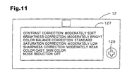
- Figs. 9 to 11 are illustrative diagrams showing exemplary display modes of liquid crystal display 127.
- Select/Set button 126 is operated to select the "Graphics Processing Control" field A1 displayed on liquid crystal display 127 (see Fig. 9)
- a "Picture Mode” field A2 and a "Graphics Processing Control Parameters” field A3 are displayed on liquid crystal display 127 (see Fig. 10).
- Picture mode is set using numbers 1, 2 ..., and graphics processing control parameters are set by entering the desired number.
- settings for individual graphics processing control parameters in the selected picture mode are shown on liquid crystal display 127, as shown in Fig. 11.
- graphics processing control parameter settings are displayed in a user-friendly way, but parameter values could be displayed instead.
- control circuit 124 determines that graphics processing control information has been set (STEP S100: Yes), it generates --in response to a shoot request, such as depression of the shutter button, for example-- graphics data GD using parameter values defined by the set graphics processing control information (STEP S110). Control circuit 124 then stores a graphics file containing the generated graphics data GD and graphics processing control information GC --which includes arbitrarily set correction conditions and automatically appended correction conditions-- on memory card MC (STEP S120). It then terminates the routine. Data generated by digital still camera 12 is converted from an RGB color space, to be represented in a YCbCr color space.
- control circuit 124 determines that graphics processing control information has not been set (STEP S100: No), it generates graphics data GD in response to a shoot request (STEP S130). Control circuit 124 then stores a graphics file containing the generated graphics data GD and graphics processing control information GC --which includes correction conditions appended automatically during creation of the graphics data -- on memory card MC (STEP S140), and then terminates the routine.
- this graphics processing control information GC is stored in color cast in a file structure having a specific file format.
- the graphics file GF stored on memory card MC is provided with graphics data GD and with graphics processing control information GC that includes correction conditions appended automatically during creation of the graphics data, and arbitrarily set correction conditions.
- Fig. 12 is a flow chart showing the processing routine for image processing by the color printer 20 pertaining to the present embodiment.
- Fig. 13 is a flow chart depicting the flow of image processing in color printer 20.
- Fig. 14 is an illustrative diagram showing the concept of automatic image quality adjustment processing in color printer 20.
- Fig. 15 is a flow chart showing the processing routine for automatic image quality adjustment in color printer 20.
- Graphics processing in the color printer 20 pertaining to the present embodiment involves first performing color space conversion, and then performing automatic image quality adjustment.
- the control circuit 30 (CPU 31) of color printer 20 reads out a graphics file GF from memory card MC, and temporarily places the graphics file GF in RAM 33 (STEP S100).
- CPU 31 searches in the appended information storage area 102 of the graphics file GF for graphics processing control information GC indicating information created at generation of the graphics data (STEP S110). If CPU 31 finds graphics processing control information (STEP S120: Yes), it acquires and analyzes the graphics processing control information GC created at generation of the graphics data (STEP S130). On the basis of the analyzed graphics processing control information GC, CPU 31 performs graphics processing, described in detail later (STEP S140), and prints out the processed graphics data (STEP S150).
- CPU 31 If CPU 31 does not find graphics processing control information (STEP S120: No), since graphics processing control information created at generation of the graphics data cannot be reflected, color printer 20 performs default graphics processing with preset defaults, i.e. parameter values, acquired from ROM 32 (STEP S160). CPU 31 prints out the processed graphics data (STEP S150) and terminates the routine.
- the CPU 31 of color printer 20 extracts graphics data GD from the read out graphics file GD (STEP S200).
- digital still camera 12 stores graphics data as JPEG format files; to increase the compression ratio, graphics data in JPEG files is stored using a YCbCr color space.
- CPU 31 performs a 3 x 3 matrix operation S to convert YCbCr graphics data to RGB graphics data (STEP S210).
- Matrix operation S is given by the equation illustrated in Figure 21.
- CPU 31 performs gamma correction and a matrix operation M on the RGB color space graphics data obtained in the preceding manner (STEP S220).
- gamma correction CPU 31 acquires the DSC gamma value from the graphics processing control information GC and uses the acquired gamma value for gamma conversion of the graphics data.
- a gamma value is included among the graphics processing control parameters designated by graphics processing control information GC.
- Matrix operation M is an operation for converting an RGB color space to an XYZ color space.
- the graphics file GF used in the present embodiment can designate color space information to be used during graphics processing, if the graphics file GF does include color space information, CPU 31 will refer to this color space information when performing matrix operation M, and will perform the matrix operation using a matrix (M) corresponding to the designated color space.
- Matrix operation M is given by the equation illustrated in Figure 22.
- the color space of the graphics data GD derived from matrix operation M is the XYZ color space.
- sRGB is the default color space used for image processing in printers and computers, so the native color space of digital still camera 12 cannot be utilized to full advantage.
- the printer modifies the matrix (M) used for matrix operation M in accordance with this color space information. Accordingly, the native color space of digital still camera 12 can be utilized effectively, so as to achieve accurate color reproduction.
- CPU 31 converts the color space of graphics data GD from the XYZ to the wRGB color space, i.e., it performs a matrix operation N -1 and inverse gamma correction (STEP S230).
- the wRGB color space is wider than the sRGB color space.
- CPU 31 acquires from ROM 32 the default gamma value for the printer, and performs inverse gamma conversion on the graphics data using the inverse of the acquired gamma value.
- matrix operation N -1 CPU 31 uses a matrix (N -1 ) --corresponding to conversion to the wRGB color space-- from ROM 31 to perform the matrix operation.
- Matrix operation N -1 is given by the equation illustrated in Figure 23.
- the color space of the graphics data GD derived from matrix operation N -1 is the wRGB color space. As noted, this wRGB color space is wider than the sRGB color space, and corresponds to the RGB color space representable by digital still camera 12.
- CPU 31 performs automatic adjustment of image quality (STEP S240).
- Graphics file GF contains graphics data GD whose image quality is to be adjusted, and graphics processing control information GC used for this image quality adjustment.
- the graphics data GD is analyzed to acquire a number of property parameter values (graphics statistical values) SV that indicate properties of the graphics data GD, which are then stored temporarily in RAM 32 (STEP 300).
- CPU 31 acquires graphics processing control information GC from the graphics file GF (STEP S310) and on the basis of this graphics processing control information GC acquires manual correction parameters MP (STEP S320).
- the manual correction parameters MP include graphics processing control parameters such as white balance, exposure bias value, exposure time, aperture, ISO, focal distance, etc. These manual correction parameters MP are independent of the result of analysis of the graphics data GD, i.e., of the graphics statistical values SV, and these values are reflected as-is in the final image quality adjustment parameters FP.
- CPU 31 determines whether the graphics processing control information GC contains a parameter value that designates a picture mode (STEP S320).
- the present embodiment employs picture modes that are combinations of a plurality of graphics processing control parameters differing for each photographed scene, when determining the automatic image quality adjustment parameters AP, i.e. automatic image quality adjustment levels that reflect the graphics statistical values SV.
- picture mode is designated by a reference number (1, 2 ... )
- the individual graphics processing control parameters that define each picture mode must be analyzed and determined on the basis of the reference number.
- CPU 31 determines that a picture mode has been designated (STEP S330: Yes)
- it analyzes the picture mode on the basis of the designated reference number, acquires the graphics processing control parameters that define the picture mode, and determines standard image quality parameter values SP by means of a process described later (STEP S340).
- manual correction parameters MP may be designated in parallel, even if picture mode is set.
- FIG. 16 is an illustrative diagram showing exemplary combinations of picture mode, image quality parameters, and numerical values designating picture mode.
- the items "contrast” and “brightness” for each picture mode are described in such a way as to facilitate understanding of the image quality resulting from automatic adjustment of image quality; the status of image quality designated by each item is analyzed by CPU 31, and the designated image quality status is produced by setting a single, or a plurality of, graphics processing control parameter values for each item.
- Picture Mode 1 is appropriate for standard a photographic condition, for example; Picture Mode 2 is appropriate for a photographic condition for portrait photography, for example; Picture Mode 3 is appropriate for a photographic condition for landscape photography, for example; Picture Mode 4 is appropriate for a photographic condition for evening photography, for example; Picture Mode 5 is appropriate for a photographic condition for night photography, for example; Picture Mode 6 is appropriate for a photographic condition for photographing flowers, for example; Picture Mode 7 is appropriate for a photographic condition for macro photography, for example; Picture Mode 8 is appropriate for a photographic condition for sports photography, for example; Picture Mode 9 is appropriate for a backlit photographic condition for example; Picture Mode 10 is appropriate for a photographic condition for photographing fall foliage, for example; and Picture Mode 11 is appropriate for a photographic condition for photographing souvenir snapshots, for example. If no picture mode is set, the parameter indicating the picture mode setting is set to "0".
- CPU 31 determines that no picture mode has been designated, i.e. that the picture mode parameter is set to "0" (STEP S330: NO), it proceeds to the process of STEP S350 in order to reflect individually set graphics processing control parameters in the image quality adjustment process.
- CPU 31 modifies (corrects) the standard values set for each parameter, while reflecting the acquired graphics processing control parameter values.
- Standard value settings for parameters are values that assume that graphics data has been generated under typical image generating conditions. In order that automatic image quality adjustment may correctly reflect the intention of the photographer (image creator), standard values are modified given especial consideration to individual graphics processing control conditions for those graphics processing control conditions that can be set by the photographer. These standard values are parameter index values for optimizing predetermined image output results by means of image evaluation by quantitative evaluation and responsive evaluation.
- the standard value for brightness is modified from its base value of 128 to a somewhat brighter value of 144
- the standard value for saturation is modified from its base value of 128 to the somewhat lower value of 102
- the standard value for sharpness is modified from its base value of 200 to the somewhat lower value of 150.
- the contrast correction coefficient is charged from it base value of 5 to a somewhat softer value of 2, while the color balance correction coefficient is left unchanged.
- Standard values and coefficients are modified, for example, by increasing or decreasing the numerical values for the standard values and coefficients, or by increasing or decreasing standard values and coefficients by predetermined percentages.
- default values of 144 for "moderately bright” and 122 for “moderately dark” may be established, and the standard value replaced depending on the trend of correction --whether this be either moderately bright or moderately dark.
- CPU 31 calculates a differential between an image quality parameter value SV and a standard image quality parameter SP corrected in the above-described manner, and designates this differential as an automatic image quality adjustment parameter AP (STEP S350).
- image quality parameter values SV are, for example, brightness of 160 and sharpness of 155
- FIG. 17 is an illustrative diagram giving exemplary AP, MP, FP and FP' values for the brightness and sharpness parameters.
- manual correction parameters MP include, for example settings of +10 for brightness and -10 for sharpness
- Fig. 18 is an illustrative diagram showing exemplary tone curves modified to reflect final image quality adjustment parameters FP.
- a tone curve for each of the RGB components is modified so as to reflect FPs for each image quality parameter, and finally the modified tone curves for the RGB components are used to perform input-output conversion for the RGB components of the graphics data GD. The result in graphics GD having adjusted image quality.
- shadow, and highlight shadow points and highlight points in the graphics data are detected, subjected to level correction on the basis of standard values, and then undergo histogram stretching. Based on standard deviation of luminance, the tone curve is corrected based on a standard value.
- graphics data is divided into 14 individual zones, and on the basis of luminance values calculated therefrom, the image is determined to be either "dark” (underexposed) or "bright” (overexposed), and the tone curve is corrected based on a standard value.
- color balance deviation is analyzed from histograms for the R component, G component, and B component of the graphics data, and the tone curves for the R component, G component, and B component are corrected on the basis of standard values to reduce color cast.
- color cast is in fact deliberately created, so color balance is not adjusted automatically, with image quality correction being performed so as the reflect the intention of the user.
- saturation the saturation distribution of the graphics data is analyzed, and saturation is enhanced on the basis of a standard value.
- the level of saturation enhancement is greater the lower the saturation of the graphics data.
- the frequency and edge intensity distribution of the graphics data are analyzed, and correction performed using an unsharp mask on the basis of standard values.
- Standard values are determined on the basis of frequency distribution, with standard values being smaller for high-frequency graphics data (such as landscapes) and larger for low-frequency graphics data (such as portraits).
- the level of application of the unsharp mask will depend on the edge intensity distribution; the level is greater the more blurry the graphics data.
- the graphics processing control parameters also include a level designating parameter LP designating an application level for the final image adjustment parameter FP, i.e., the extent to which graphics data DG will be brought into approximation with graphics data based on standard values.
- LP 10
- the final image adjustment parameter AP value will be multiplied by a factor of 2
- the standard value for sharpness is modified on the basis of lens focal distance and F number when the picture is taken.
- “blur” is determined by the lens focal distance and F number (aperture).
- the standard value for sharpness is associated with lens focal distance and F number so as to enable image quality adjustment processing to reflect hypothetical blur when shooting. For example, for a wide-angle lens (i.e. 35 mm or smaller) at F13 (stopped down), it may generally be assumed that the intention of the photographer is for the entire scene --ranging from the foreground to the background-- of a landscape or souvenir shot to be in sharp focus.
- image quality processing is performed by decreasing the standard value for sharpness so that most image features are sharp, and increasing the level of sharpness application to provide sharpness.
- image quality processing is performed by increasing the standard value for sharpness to provide sharpness exclusively at the transition from subject to background --without sharpening smooth areas such as the skin-- and decreasing the level of sharpness application to provide roughness to skin, etc.
- Fig. 19 is an illustrative diagram describing a blurriness index f/F calculated from lens focal distance f (mm) and the F number.
- CPU 31 After performing automatic image quality adjustment as described above (STEP S360), CPU 31 returns to the main routine, i.e., the graphics processing routine.
- CPU 31 After completing automatic image quality adjustment processing, CPU 31 performs wRGB conversion and halftone processing for printing (STEP S250).
- CPU 31 refers to a lookup table (LUT) for CMYK color space conversion, associated with the wRGB color space and stored in ROM 31, and converts the graphics data from the wRGB color space to a CMYK color space.
- LUT lookup table
- graphics data consisting of R ⁇ G ⁇ B grayscale values is converted, for example, to grayscale data for each of six colors C M ⁇ Y ⁇ K ⁇ LC ⁇ LM, used by the color printer 20.
- the color-converted graphics data is subjected to grayscaling.
- color-converted graphics data is represented as data having 256 shades for each color.
- the color printer 20 in the embodiment can only assume one of two states: "print a dot" or "do not print a dot". That is, the color printer 20 herein can only produce two shades in a given location.
- 256-shade image data is converted into image data that the color printer 20 can represent using two shades.
- Representative methods for two-shade conversion are the error diffusion technique and the systematic dithering technique.
- color printer 20 if, prior to color conversion, the resolution of graphics data is lower than the print resolution, new data lying between adjacent image data is generated by means of linear interpolation; if, conversely, it is higher than the print resolution, a resolution conversion process wherein data is divided by a certain ratio to convert the graphics data resolution to the print resolution is performed.
- Color printer 20 subjects graphics data converted to dot print/not print format to an interlacing process wherein the data is rearranged in the sequence in which it will be sent to the color printer 20.
- graphics processing control conditions for image quality adjustment processing by the printer 20 can be set from the digital still camera 12. It is therefore possible to make any desired graphics processing control condition settings when taking a picture, and to have image quality adjustment performed in such a way as to properly reflect the graphics processing control conditions desired when the picture is taken. Further, graphics processing control conditions assumed when taking a picture can be easily associated with the graphics data, and individual graphics processing control conditions can be imparted to individual sets of graphics data. Further, there is no need to reset graphics processing control conditions during automatic adjustment of image quality of graphics data, facilitating image quality adjustment that reflects graphics processing control conditions.
- image quality of graphics data GD can be adjusted automatically so as to reflect graphics processing control information GC included in the graphics file GF.
- image quality can be adjusted automatically in an appropriate manner for individual sets of graphics data, so as to reflect photographic conditions when a picture is taken.
- image quality is adjusted automatically so as to reflect the intentionally set graphics processing control conditions, thus solving a problem pertaining to conventional automatic image quality adjustment, namely, that intentionally set graphics processing control conditions are corrected so that image does not reflect the intent of the user.
- image quality adjustment is performed automatically; however, it would be possible to provide an automatic image quality adjustment button on the control panel of the color printer 20, so as to allow automatic image quality adjustment herein to be performed only when automatic image quality adjustment has been selected by means of the automatic image quality adjustment button.
- graphics processing control information GC is reflected by a process of analyzing the graphics processing control information GC, acquiring graphics processing control parameters, and modifying standard values and application levels; however, graphics data GD could be corrected directly on the basis of graphics processing control information GC. This could be accomplished by having graphics processing control information GC include information indicating the extent to which the graphics data GD should be modified, for example, increasing the brightness correction level by +10 to increase brightness by +10%. With this arrangement, image quality adjustment may be made to reflect the trend of correction intended by the user, unaffected by the image quality properties of the graphics data GD.
- all image processing is performed in the color printer 20 without the aid of a personal computer PC, and a dot pattern is produced on a print medium according to the graphics data GD generated thereby.
- all or a portion of the image processing could be performed on a computer, or on a server over a network. This could be achieved by means of a graphics data processing application (program) --namely, a retouching application or printer driver-- installed on the hard disk etc. of a computer, and having an image processing function described with reference to Fig. 14.
- An graphics file GF generated by digital still camera 12 is supplied to the computer via a cable or memory card MC.
- the application is run on the computer under user control, whereupon the application reads the graphics file GF, analyzes the graphics processing control information GC, and converts and adjusts the graphics data GD.
- the application can be designed to run automatically when detecting insertion of a memory card MC or detecting attachment of a cable, whereupon the application reads the graphics file GF, analyzes the graphics processing control information GC, and converts and adjusts the graphics data GD automatically.
- Property parameter values for automatic image quality adjustment may be made selectable. This could be accomplished, for example, by providing color printer 20 with parameter selection buttons, or with picture mode parameter selection buttons for setting predetermined parameter combinations for different subjects, so as to allow parameters for automatic image quality adjustment to be selected by means of the selection buttons. Where automatic image quality adjustment is performed on a computer, parameters for automatic image quality adjustment could be selected from the user interface of the printer driver or retouching application.
- Graphics processing by color printer 20 may be performed prior to automatic image quality adjustment, as shown in Fig. 20 with color space conversion performed afterward.
- Basic information may be processed.
- a display device such as a CRT, LCD, projector etc. could also be used as the output device.
- an graphics processing program (display driver) for executing the image processing described in Fig. 12,13 etc., for example, could be used.
- the CRT etc. functions as a display device for a computer
- the graphics processing program can be run on the computer.
- the final output graphics data will have an RGB color space, not a CMYK color space.
- picture mode and graphics processing control parameters are set from the digital still camera 12, and the picture mode and graphics processing control parameters settings are then analyzed by printer 20, after which standard values are modified.
- automatic image quality adjustment of graphics data GD is performed with graphics processing control commands.
- the process for modifying standard values from picture mode and graphics processing control parameters could be performed in digital still camera 12, and standard values and application levels, i.e., values per se, provided to printer 20.
- image quality adjustment for individual photographic conditions and image quality adjustment reflecting user intention can be performed automatically by providing a printer 20 an image quality adjustment function that uses standard values.
- graphics processing control information GC includes the parameters of light source, exposure bias value, target color space, brightness and sharpness, but it is an arbitrary decision which parameters will be used as graphics processing control information GC.
- matrix M and matrix N -1 operations are performed independently when converting color space properties from the sRGB color space to the wRGB color space
- MN -1 composite matrix
- Any of various conversion matrices may be composed if necessary.
- Composite matrices enable series of matrix operations to be performed more rapidly.
- the graphics file format herein is not limited thereto. It is possible to use any graphics file that includes graphics data generated by a graphics data generating device, and graphics processing control information GC describing conditions at generation (information) of the graphics data. The use of such files enables graphics data generated by a graphics data generating device to have its image quality adjusted automatically for output by an output device.
- the digital still camera 12 and color printer 20 used in the preceding embodiment are merely exemplary, and the arrangement thereof is not limited to that described in the embodiment.
- the digital still camera 12 it is sufficient for the device to have, at a minimum, the function of generating the graphics file GF herein.
- color printer 20 it is sufficient for the device to be capable, at a minimum, of analyzing graphics processing control information GC in the graphics file GF herein, automatically adjusting image quality (especially brightness) to reflect user intention, and outputting (printing) the image.
- Graphics files GF that contain graphics data and graphics processing control information GC include files created by generating association data associated with graphics processing control information GC, and storing one, or a plurality of, sets of graphics data and graphics processing control information GC in separate files, so as to enable the image data and graphics processing control information GC to be associated by referring to the association data during image processing. While in this case graphics data and graphics processing control information GC are stored in separate files, during image processing using the graphics processing control information GC, the graphics data and graphics processing control information GC are indivisibly united, so functionality is substantially the same as with storage in a single file. That is, the use of associated graphics data and graphics processing control information GC --at least during image processing-- is included in the definition of "graphics file GF" herein. Motion video files stored on optical media such as CD-ROM, CD-R, DVD-ROM and DVD-RAM are also included.
Applications Claiming Priority (6)
| Application Number | Priority Date | Filing Date | Title |
|---|---|---|---|
| JP2001008866 | 2001-01-17 | ||
| JP2001008866 | 2001-01-17 | ||
| JP2001074671 | 2001-03-15 | ||
| JP2001074671 | 2001-03-15 | ||
| JP2001249912A JP3725454B2 (ja) | 2001-01-17 | 2001-08-21 | 画像ファイルの出力画像調整 |
| JP2001249912 | 2001-08-21 |
Publications (2)
| Publication Number | Publication Date |
|---|---|
| EP1241870A2 true EP1241870A2 (de) | 2002-09-18 |
| EP1241870A3 EP1241870A3 (de) | 2005-06-22 |
Family
ID=27345736
Family Applications (1)
| Application Number | Title | Priority Date | Filing Date |
|---|---|---|---|
| EP02001259A Withdrawn EP1241870A3 (de) | 2001-01-17 | 2002-01-17 | Ausgabebildeinstellungsverfahren, Vorrichtung und Rechnerprogrammprodukt für Bilddateien |
Country Status (4)
| Country | Link |
|---|---|
| US (2) | US7375848B2 (de) |
| EP (1) | EP1241870A3 (de) |
| JP (1) | JP3725454B2 (de) |
| CN (2) | CN1674637A (de) |
Cited By (4)
| Publication number | Priority date | Publication date | Assignee | Title |
|---|---|---|---|---|
| EP1365585A1 (de) * | 2001-02-09 | 2003-11-26 | Seiko Epson Corporation | Bilddateierzeugung und bildverarbeitung |
| EP1473925A2 (de) * | 2003-05-01 | 2004-11-03 | Seiko Epson Corporation | Bildverarbeitung zur Gegenlichtkorrektur unter Verwendung von Bildaufnahmeinformationsdaten |
| US7782366B2 (en) | 2002-09-20 | 2010-08-24 | Seiko Epson Corporation | Backlight adjustment processing of image using image generation record information |
| US8279481B2 (en) | 2002-05-07 | 2012-10-02 | Seiko Epson Corporation | Update control of image processing control data |
Families Citing this family (57)
| Publication number | Priority date | Publication date | Assignee | Title |
|---|---|---|---|---|
| JP3520860B2 (ja) * | 2001-02-09 | 2004-04-19 | セイコーエプソン株式会社 | 画像ファイルの出力画像調整 |
| US7385610B2 (en) * | 2001-10-18 | 2008-06-10 | Hewlett-Packard Development Company, L.P. | System and method for displaying graphics |
| CN100553315C (zh) * | 2002-07-11 | 2009-10-21 | 精工爱普生株式会社 | 图象数据的输出图像调整 |
| US7379213B2 (en) | 2002-07-11 | 2008-05-27 | Seiko Epson Corporation | Output image adjustment of image data |
| US7511853B2 (en) | 2002-07-11 | 2009-03-31 | Seiko Epson Corporation | Adjustment for output image of image data |
| JP4217458B2 (ja) * | 2002-10-28 | 2009-02-04 | キヤノン株式会社 | 印刷システム、外部操作装置、情報処理装置、データ処理方法、記憶媒体 |
| KR100943274B1 (ko) * | 2002-12-20 | 2010-02-23 | 삼성전자주식회사 | 색신호 보정장치 및 그 방법, 및 그것을 이용한영상신호처리 시스템 및 그 방법 |
| US20040135790A1 (en) * | 2003-01-15 | 2004-07-15 | Xerox Corporation | Correcting the color cast of an image |
| JP4093084B2 (ja) * | 2003-03-12 | 2008-05-28 | セイコーエプソン株式会社 | 印刷ジョブ作成装置および印刷ジョブ作成方法並びにこれらに用いるプログラム |
| US7277126B2 (en) | 2003-07-11 | 2007-10-02 | Seiko Epson Corporation | Image data quality adjustment |
| JP4466565B2 (ja) | 2003-09-09 | 2010-05-26 | セイコーエプソン株式会社 | 出力画像データ生成装置および出力画像データ生成方法 |
| JP3901173B2 (ja) * | 2004-06-07 | 2007-04-04 | セイコーエプソン株式会社 | 画像処理装置、画像処理方法及び画像処理プログラム |
| US7751643B2 (en) * | 2004-08-12 | 2010-07-06 | Semiconductor Insights Inc. | Method and apparatus for removing uneven brightness in an image |
| JP4367929B2 (ja) * | 2004-08-27 | 2009-11-18 | キヤノン株式会社 | 携帯電話及び印刷システムとその制御方法 |
| JP4453915B2 (ja) * | 2005-03-18 | 2010-04-21 | 富士通株式会社 | クロスバー装置、制御方法及びプログラム |
| JP5010114B2 (ja) * | 2005-06-15 | 2012-08-29 | Necディスプレイソリューションズ株式会社 | 映像調整システム及び映像調整方法 |
| US20070019258A1 (en) * | 2005-07-22 | 2007-01-25 | Brother Kogyo Kabushiki Kaisha | Image forming system |
| JP4725255B2 (ja) * | 2005-09-07 | 2011-07-13 | セイコーエプソン株式会社 | 画像表示装置、プロジェクタ、パラメータセット選択方法、及びパラメータセット記憶方法 |
| US20070070436A1 (en) * | 2005-09-23 | 2007-03-29 | Kabushiki Kaisha Toshiba | Image forming apparatus and method of controlling the apparatus |
| JP5020517B2 (ja) * | 2006-02-02 | 2012-09-05 | キヤノン株式会社 | 印刷システム、印刷装置、撮像装置、及び制御方法 |
| JP4506683B2 (ja) * | 2006-02-15 | 2010-07-21 | セイコーエプソン株式会社 | 画像処理装置、コンピュータプログラム、画像出力装置および画質調整方法 |
| JP4363412B2 (ja) * | 2006-05-11 | 2009-11-11 | ブラザー工業株式会社 | 画像形成装置、印刷制御プログラム、アプリケーションプログラム、及び、印刷システム |
| JP4315176B2 (ja) * | 2006-09-29 | 2009-08-19 | セイコーエプソン株式会社 | 印刷装置、印刷方法、および、印刷用プログラム |
| US8296662B2 (en) * | 2007-02-05 | 2012-10-23 | Brother Kogyo Kabushiki Kaisha | Image display device |
| JP2008211310A (ja) * | 2007-02-23 | 2008-09-11 | Seiko Epson Corp | 画像処理装置および画像表示装置 |
| JP4687673B2 (ja) * | 2007-03-19 | 2011-05-25 | セイコーエプソン株式会社 | カラー画像のモノトーン化処理 |
| US8243328B2 (en) | 2007-04-20 | 2012-08-14 | Seiko Epson Corporation | Printing method, printing apparatus, and storage medium storing a program |
| WO2008137432A2 (en) * | 2007-05-01 | 2008-11-13 | Dyyno | Sharing of information and formatting information for transmission over a communication network |
| JP4882927B2 (ja) | 2007-08-31 | 2012-02-22 | セイコーエプソン株式会社 | カテゴリ識別方法 |
| JP4978378B2 (ja) | 2007-08-31 | 2012-07-18 | セイコーエプソン株式会社 | 画像処理装置 |
| JP4946741B2 (ja) | 2007-09-05 | 2012-06-06 | セイコーエプソン株式会社 | 画像処理装置、画像処理方法、及び画像処理システム |
| JP2010118753A (ja) * | 2008-11-11 | 2010-05-27 | Sharp Corp | 再生装置、再生装置の制御プログラム、および再生装置の制御プログラムを記録した記録媒体 |
| JP2009081885A (ja) * | 2009-01-05 | 2009-04-16 | Seiko Epson Corp | 画像データの出力調整 |
| JP2011071796A (ja) * | 2009-09-28 | 2011-04-07 | Hitachi Consumer Electronics Co Ltd | 撮像装置およびその画質調整方法 |
| KR101595262B1 (ko) * | 2009-10-26 | 2016-02-18 | 삼성전자주식회사 | 보안 기능을 구비한 영상 처리 장치 및 방법 |
| JP2010027077A (ja) * | 2009-11-02 | 2010-02-04 | Seiko Epson Corp | カメラ、並びに画像の輝度調整方法及びプログラム |
| US8666148B2 (en) | 2010-06-03 | 2014-03-04 | Adobe Systems Incorporated | Image adjustment |
| JP5791244B2 (ja) * | 2010-07-29 | 2015-10-07 | キヤノン株式会社 | 画像処理装置、表示装置及びそれらの制御方法 |
| WO2012066610A1 (ja) * | 2010-11-19 | 2012-05-24 | 三菱電機株式会社 | 表示ユニット、撮像ユニット及び表示システム装置 |
| JP5067489B2 (ja) * | 2011-02-09 | 2012-11-07 | セイコーエプソン株式会社 | 画像データの出力画像調整 |
| US8903169B1 (en) | 2011-09-02 | 2014-12-02 | Adobe Systems Incorporated | Automatic adaptation to image processing pipeline |
| US9008415B2 (en) | 2011-09-02 | 2015-04-14 | Adobe Systems Incorporated | Automatic image adjustment parameter correction |
| CN103079047B (zh) * | 2012-12-25 | 2016-07-20 | 华为技术有限公司 | 一种参数调整的方法及终端 |
| JP6288081B2 (ja) * | 2013-04-17 | 2018-03-07 | コニカミノルタ株式会社 | 色処理装置、画像形成装置及び色処理方法 |
| JP5862689B2 (ja) * | 2014-01-06 | 2016-02-16 | セイコーエプソン株式会社 | 画像データ出力調整装置、画像データ出力調整方法、画像データ出力調整プログラム、および撮像装置 |
| US10182241B2 (en) * | 2014-03-04 | 2019-01-15 | Microsoft Technology Licensing, Llc | Encoding strategies for adaptive switching of color spaces, color sampling rates and/or bit depths |
| RU2653295C2 (ru) | 2014-03-04 | 2018-05-07 | МАЙКРОСОФТ ТЕКНОЛОДЖИ ЛАЙСЕНСИНГ, ЭлЭлСи | Адаптивное переключение цветовых пространств, частот цветовой дискретизации и/или битовых глубин |
| BR112016021529B1 (pt) | 2014-03-27 | 2023-02-28 | Microsoft Technology Licensing, Llc | Dispositivo de computação, método e meio legível por computador para ajuste de quantização/escalada e quantização/escalada inversa ao alternar áreas de cor |
| US10687069B2 (en) | 2014-10-08 | 2020-06-16 | Microsoft Technology Licensing, Llc | Adjustments to encoding and decoding when switching color spaces |
| JP5888442B2 (ja) * | 2015-01-26 | 2016-03-22 | セイコーエプソン株式会社 | 画像データ出力調整装置、画像データ出力調整方法、画像データ出力調整プログラムおよび撮像装置 |
| JP2016067040A (ja) * | 2015-12-21 | 2016-04-28 | セイコーエプソン株式会社 | 画像データ出力調整装置、画像データ出力調整方法、画像データ出力調整プログラムおよび撮像装置 |
| CN106297631B (zh) * | 2016-08-30 | 2019-06-04 | 南京巨鲨显示科技有限公司 | 一种具有曲线数据纠错功能的显示器及其纠错方法 |
| CN106649701A (zh) * | 2016-12-20 | 2017-05-10 | 新乡学院 | 一种美术作品筛选展示系统 |
| US10497105B2 (en) * | 2017-11-01 | 2019-12-03 | Google Llc | Digital image auto exposure adjustment |
| CN109350109B (zh) * | 2018-12-06 | 2022-03-04 | 北京锐视康科技发展有限公司 | 多功能牙科扫描系统 |
| JP7332367B2 (ja) * | 2019-07-10 | 2023-08-23 | キヤノン株式会社 | 画像処理装置、及び画像処理方法 |
| CN111091518B (zh) * | 2019-12-31 | 2023-05-02 | 北京金山云网络技术有限公司 | 一种图像处理方法、装置、电子设备及存储介质 |
Citations (6)
| Publication number | Priority date | Publication date | Assignee | Title |
|---|---|---|---|---|
| US4792847A (en) * | 1985-11-09 | 1988-12-20 | Fuji Photo Film Co., Ltd. | Method for automatically setting signal processing conditions in image input/output system |
| US5495349A (en) * | 1990-01-13 | 1996-02-27 | Canon Kabushiki Kaisha | Color image processing apparatus that stores processing parameters by character data |
| EP0757473A2 (de) * | 1995-08-01 | 1997-02-05 | Canon Kabushiki Kaisha | Bildverarbeitungsgerät und -verfahren |
| EP0838939A2 (de) * | 1996-10-22 | 1998-04-29 | Fuji Photo Film Co., Ltd. | Verfahren und Vorrichtung zur Bildwiedergabe aus Daten einer digitalen Kamera und digitale Kamera dafür |
| JPH1127535A (ja) * | 1997-07-04 | 1999-01-29 | Dainippon Screen Mfg Co Ltd | 画像処理パラメータ決定装置およびその方法 |
| JPH1188672A (ja) * | 1997-07-14 | 1999-03-30 | Fuji Photo Film Co Ltd | 画像処理方法および装置、画像再生方法および装置並びにその方法に使用する画像確認装置 |
Family Cites Families (23)
| Publication number | Priority date | Publication date | Assignee | Title |
|---|---|---|---|---|
| US678814A (en) * | 1900-11-15 | 1901-07-16 | Addison H Riggs | Tap. |
| US4216480A (en) * | 1978-11-13 | 1980-08-05 | International Business Machines Corporation | Multiple speed ink jet printer |
| JPS6062779A (ja) * | 1983-08-31 | 1985-04-10 | Nec Corp | インクジェット記録方法 |
| JP3179576B2 (ja) | 1992-06-29 | 2001-06-25 | 富士写真フイルム株式会社 | プリンタシステム |
| US6771889B1 (en) * | 1995-10-03 | 2004-08-03 | Canon Kabushiki Kaisha | Data storage based on serial numbers |
| US6192191B1 (en) * | 1995-10-03 | 2001-02-20 | Canon Kabushiki Kaisha | Data storage based on serial numbers |
| JPH09219817A (ja) | 1996-02-09 | 1997-08-19 | Nikon Corp | フィルム画像表示装置 |
| JPH10226139A (ja) * | 1997-02-14 | 1998-08-25 | Canon Inc | 画像形成システム及び画像形成装置及び媒体 |
| JPH1141622A (ja) | 1997-07-22 | 1999-02-12 | Ricoh Co Ltd | 画像処理装置 |
| JP3911354B2 (ja) | 1997-09-02 | 2007-05-09 | 大日本スクリーン製造株式会社 | 画像処理方法および装置、並びにその処理を実行するためのプログラムを記録した記録媒体 |
| JP3899497B2 (ja) | 1997-10-24 | 2007-03-28 | 株式会社ニコン | 電子カメラ、電子カメラの制御方法、および、記録媒体 |
| DE19757440A1 (de) | 1997-12-23 | 1999-06-24 | Thomson Brandt Gmbh | Automatisiertes Einstellen der Verstärkung in Regelkreisen |
| US6834130B1 (en) * | 1998-02-18 | 2004-12-21 | Minolta Co., Ltd. | Image retrieval system for retrieving a plurality of images which are recorded in a recording medium, and a method thereof |
| JPH11239269A (ja) | 1998-02-23 | 1999-08-31 | Fuji Photo Film Co Ltd | 画像処理方法 |
| JP3668014B2 (ja) | 1998-03-09 | 2005-07-06 | 富士写真フイルム株式会社 | 画像処理方法及び装置 |
| JPH11298848A (ja) | 1998-04-13 | 1999-10-29 | Minolta Co Ltd | デジタルカメラ |
| JP2000013718A (ja) | 1998-06-18 | 2000-01-14 | Olympus Optical Co Ltd | 画像印刷装置 |
| US6822758B1 (en) * | 1998-07-01 | 2004-11-23 | Canon Kabushiki Kaisha | Image processing method, system and computer program to improve an image sensed by an image sensing apparatus and processed according to a conversion process |
| US6785814B1 (en) * | 1998-07-28 | 2004-08-31 | Fuji Photo Film Co., Ltd | Information embedding method and apparatus |
| JP4095184B2 (ja) | 1998-10-29 | 2008-06-04 | キヤノン株式会社 | 画像処理装置及びその方法 |
| JP2000278598A (ja) | 1999-03-19 | 2000-10-06 | Minolta Co Ltd | デジタルカメラおよび記録媒体 |
| JP4213297B2 (ja) * | 1999-06-11 | 2009-01-21 | 富士フイルム株式会社 | 撮影装置 |
| JP2001147481A (ja) | 1999-11-18 | 2001-05-29 | Canon Inc | カメラ、プリンタ装置及び写真プリントシステム |
-
2001
- 2001-08-21 JP JP2001249912A patent/JP3725454B2/ja not_active Expired - Lifetime
-
2002
- 2002-01-15 US US10/051,805 patent/US7375848B2/en active Active
- 2002-01-17 CN CNA2005100674166A patent/CN1674637A/zh active Pending
- 2002-01-17 CN CN02102338A patent/CN1366421A/zh active Pending
- 2002-01-17 EP EP02001259A patent/EP1241870A3/de not_active Withdrawn
-
2008
- 2008-04-07 US US12/080,994 patent/US20080198396A1/en not_active Abandoned
Patent Citations (6)
| Publication number | Priority date | Publication date | Assignee | Title |
|---|---|---|---|---|
| US4792847A (en) * | 1985-11-09 | 1988-12-20 | Fuji Photo Film Co., Ltd. | Method for automatically setting signal processing conditions in image input/output system |
| US5495349A (en) * | 1990-01-13 | 1996-02-27 | Canon Kabushiki Kaisha | Color image processing apparatus that stores processing parameters by character data |
| EP0757473A2 (de) * | 1995-08-01 | 1997-02-05 | Canon Kabushiki Kaisha | Bildverarbeitungsgerät und -verfahren |
| EP0838939A2 (de) * | 1996-10-22 | 1998-04-29 | Fuji Photo Film Co., Ltd. | Verfahren und Vorrichtung zur Bildwiedergabe aus Daten einer digitalen Kamera und digitale Kamera dafür |
| JPH1127535A (ja) * | 1997-07-04 | 1999-01-29 | Dainippon Screen Mfg Co Ltd | 画像処理パラメータ決定装置およびその方法 |
| JPH1188672A (ja) * | 1997-07-14 | 1999-03-30 | Fuji Photo Film Co Ltd | 画像処理方法および装置、画像再生方法および装置並びにその方法に使用する画像確認装置 |
Cited By (8)
| Publication number | Priority date | Publication date | Assignee | Title |
|---|---|---|---|---|
| EP1365585A1 (de) * | 2001-02-09 | 2003-11-26 | Seiko Epson Corporation | Bilddateierzeugung und bildverarbeitung |
| EP1365585A4 (de) * | 2001-02-09 | 2005-10-12 | Seiko Epson Corp | Bilddateierzeugung und bildverarbeitung |
| US7825962B2 (en) | 2001-02-09 | 2010-11-02 | Seiko Epson Corporation | Image generation with integrating control data |
| US8279481B2 (en) | 2002-05-07 | 2012-10-02 | Seiko Epson Corporation | Update control of image processing control data |
| US8559044B2 (en) | 2002-05-07 | 2013-10-15 | Seiko Epson Corporation | Update control of image processing control data |
| US7782366B2 (en) | 2002-09-20 | 2010-08-24 | Seiko Epson Corporation | Backlight adjustment processing of image using image generation record information |
| EP1473925A2 (de) * | 2003-05-01 | 2004-11-03 | Seiko Epson Corporation | Bildverarbeitung zur Gegenlichtkorrektur unter Verwendung von Bildaufnahmeinformationsdaten |
| EP1473925A3 (de) * | 2003-05-01 | 2009-04-01 | Seiko Epson Corporation | Bildverarbeitung zur Gegenlichtkorrektur unter Verwendung von Bildaufnahmeinformationsdaten |
Also Published As
| Publication number | Publication date |
|---|---|
| US20080198396A1 (en) | 2008-08-21 |
| CN1674637A (zh) | 2005-09-28 |
| US7375848B2 (en) | 2008-05-20 |
| CN1366421A (zh) | 2002-08-28 |
| JP3725454B2 (ja) | 2005-12-14 |
| US20020140693A1 (en) | 2002-10-03 |
| EP1241870A3 (de) | 2005-06-22 |
| JP2002344989A (ja) | 2002-11-29 |
Similar Documents
| Publication | Publication Date | Title |
|---|---|---|
| US7375848B2 (en) | Output image adjustment method, apparatus and computer program product for graphics files | |
| JP4333804B2 (ja) | 画像データの出力画像調整 | |
| JP3849706B2 (ja) | 光源の種類に応じた画質の自動調整 | |
| US20080174677A1 (en) | Graphics data generation device and graphics data generation method | |
| US20090237694A1 (en) | Automatic image quality adjustment according to size of subject | |
| JP2003060935A (ja) | 画像ファイルの出力画像調整 | |
| JP4015066B2 (ja) | 画像ファイルの出力画像調整 | |
| JP4266716B2 (ja) | 画像ファイルの出力画像調整 | |
| EP1524854B1 (de) | Bildqualitätseinstellung von bilddaten | |
| JP5045808B2 (ja) | 画像ファイルの出力画像調整 | |
| JP3834516B2 (ja) | 画像データの出力画像調整 | |
| JP3999157B2 (ja) | 画像ファイルの出力画像調整 | |
| JP4126967B2 (ja) | 画像データの出力画像調整 | |
| JP5206741B2 (ja) | 画像ファイルの生成および出力 |
Legal Events
| Date | Code | Title | Description |
|---|---|---|---|
| PUAI | Public reference made under article 153(3) epc to a published international application that has entered the european phase |
Free format text: ORIGINAL CODE: 0009012 |
|
| AK | Designated contracting states |
Kind code of ref document: A2 Designated state(s): AT BE CH CY DE DK ES FI FR GB GR IE IT LI LU MC NL PT SE TR |
|
| AX | Request for extension of the european patent |
Free format text: AL;LT;LV;MK;RO;SI |
|
| PUAL | Search report despatched |
Free format text: ORIGINAL CODE: 0009013 |
|
| AK | Designated contracting states |
Kind code of ref document: A3 Designated state(s): AT BE CH CY DE DK ES FI FR GB GR IE IT LI LU MC NL PT SE TR |
|
| AX | Request for extension of the european patent |
Extension state: AL LT LV MK RO SI |
|
| RIC1 | Information provided on ipc code assigned before grant |
Ipc: 7H 04N 1/46 B Ipc: 7H 04N 1/60 A |
|
| 17P | Request for examination filed |
Effective date: 20050613 |
|
| AKX | Designation fees paid |
Designated state(s): AT BE CH CY DE DK ES FI FR GB GR IE IT LI LU MC NL PT SE TR |
|
| 17Q | First examination report despatched |
Effective date: 20061025 |
|
| STAA | Information on the status of an ep patent application or granted ep patent |
Free format text: STATUS: THE APPLICATION IS DEEMED TO BE WITHDRAWN |
|
| 18D | Application deemed to be withdrawn |
Effective date: 20091128 |