EP1241303A2 - Fussbodenpaneel - Google Patents
Fussbodenpaneel Download PDFInfo
- Publication number
- EP1241303A2 EP1241303A2 EP02005474A EP02005474A EP1241303A2 EP 1241303 A2 EP1241303 A2 EP 1241303A2 EP 02005474 A EP02005474 A EP 02005474A EP 02005474 A EP02005474 A EP 02005474A EP 1241303 A2 EP1241303 A2 EP 1241303A2
- Authority
- EP
- European Patent Office
- Prior art keywords
- groove
- floor panel
- tongue
- panel according
- panels
- Prior art date
- Legal status (The legal status is an assumption and is not a legal conclusion. Google has not performed a legal analysis and makes no representation as to the accuracy of the status listed.)
- Granted
Links
- 230000000284 resting effect Effects 0.000 claims 1
- 210000003746 feather Anatomy 0.000 description 4
- 239000000463 material Substances 0.000 description 3
- 239000000428 dust Substances 0.000 description 2
- 230000015572 biosynthetic process Effects 0.000 description 1
- 238000003780 insertion Methods 0.000 description 1
- 230000037431 insertion Effects 0.000 description 1
- 239000002689 soil Substances 0.000 description 1
- 230000008961 swelling Effects 0.000 description 1
- 239000002023 wood Substances 0.000 description 1
Images

Classifications
-
- E—FIXED CONSTRUCTIONS
- E04—BUILDING
- E04F—FINISHING WORK ON BUILDINGS, e.g. STAIRS, FLOORS
- E04F15/00—Flooring
- E04F15/02—Flooring or floor layers composed of a number of similar elements
-
- E—FIXED CONSTRUCTIONS
- E04—BUILDING
- E04F—FINISHING WORK ON BUILDINGS, e.g. STAIRS, FLOORS
- E04F15/00—Flooring
- E04F15/02—Flooring or floor layers composed of a number of similar elements
- E04F15/04—Flooring or floor layers composed of a number of similar elements only of wood or with a top layer of wood, e.g. with wooden or metal connecting members
-
- E—FIXED CONSTRUCTIONS
- E04—BUILDING
- E04F—FINISHING WORK ON BUILDINGS, e.g. STAIRS, FLOORS
- E04F2201/00—Joining sheets or plates or panels
- E04F2201/01—Joining sheets, plates or panels with edges in abutting relationship
- E04F2201/0153—Joining sheets, plates or panels with edges in abutting relationship by rotating the sheets, plates or panels around an axis which is parallel to the abutting edges, possibly combined with a sliding movement
-
- E—FIXED CONSTRUCTIONS
- E04—BUILDING
- E04F—FINISHING WORK ON BUILDINGS, e.g. STAIRS, FLOORS
- E04F2201/00—Joining sheets or plates or panels
- E04F2201/02—Non-undercut connections, e.g. tongue and groove connections
- E04F2201/023—Non-undercut connections, e.g. tongue and groove connections with a continuous tongue or groove
-
- E—FIXED CONSTRUCTIONS
- E04—BUILDING
- E04F—FINISHING WORK ON BUILDINGS, e.g. STAIRS, FLOORS
- E04F2201/00—Joining sheets or plates or panels
- E04F2201/02—Non-undercut connections, e.g. tongue and groove connections
- E04F2201/025—Non-undercut connections, e.g. tongue and groove connections with tongue and grooves alternating transversally in the direction of the thickness of the panel, e.g. multiple tongue and grooves oriented parallel to each other
Definitions
- the invention relates to a floor panel that is limited in the horizontal plane from a top provided with a decorative layer or the like and one to Support on a subfloor provided on at least two opposite sides each have a groove and a tongue, the groove on one side is essentially congruent with the spring on the other side.
- Such a floor panel is known for example from DE 33 43 601 A1.
- To Connection of two panels are continuous profile bars at the edges to be connected provided that by merely joining them together in the transverse direction are connectable that the plates both to the plate level and perpendicular to Plate level are coupled together.
- the profile bars must match the plate edges be glued. For this, the side edges must have corresponding recesses be provided. As long as the profile bars are not connected to the panels the thin decorative layer is exposed over a clear area and can be improper Break out of handling, causing the bottom plate to become unusable is and can no longer be used as a floor covering.
- the panels are made of a wooden material, especially MDF or HDF.
- the top is formed by a decorative layer applied to the MDF board.
- To Panels composed of a floor covering must be at the junction of the Be tight on the top so that no moisture can penetrate into the connection point can, which would lead to the swelling of the base material of the panels.
- the locking means are designed so that two nested panels are under tension and the connection points are firmly pressed together at the top become.
- the panels must be on the long sides as well as on the Cross pages are connected to each other. When laying are usually first the long sides joined together. Then the last panel attached be moved in the longitudinal direction to be connected to the transverse side can.
- CH 684 544 A5 discloses a base plate, especially for highly stressed Floor coverings that each have a groove and a projection at the edge areas, the projection being congruent to the groove on the opposite side. To the Connect the plates into each other so that the protrusion in the corresponding Engages groove.
- a generic floor panel is characterized by that the groove and the tongue directly adjoin one another and the groove base of both Grooves are inclined at an angle to the top.
- This design allows two panels to be pivoted into one another for connection become.
- the springs can be made short and thus stable by this configuration become.
- the angle of inclination is preferably between 30 ° and 50 ° and in particular 45 °.
- the groove is one Side open to the bottom and the groove of the opposite side to the top open.
- the groove open toward the top preferably has an undercut into which the spring directed towards the underside with an appropriately designed projection can intervene. As a result, the panels are locked together.
- the radius of curvature for the tongue and the groove are preferably identical.
- the undercut can be formed by a fillet.
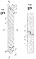
- the floor panels 1, 2 consist of a core made of wood-based material.
- the top 13 has a decorative layer 11.
- the grooves 4, 8 close immediately to the springs 3, 7 so that they have a common wall 4a, 8a.
- the groove base 5, 9 of both grooves 4, 8 extends at an angle ⁇ of approximately 45 ° to Top 13.
- the wall 8a of the groove 8 open towards the top 13 runs perpendicular to its groove base 9.
- the opposite wall is provided with an undercut 10, which was produced by rounding off with the radius r 1 .
- the tongue 3 congruent to this groove 8 on the opposite side is rounded at its edges with the radius r 2 , the radii r 1 and r 2 being the same.
- the wall 3a of the tongue 3 facing away from the groove 4 is provided with a bulge corresponding to the undercut 10, so that in the case of two panels 1, 2 connected to one another, the tongue 3 latches with the groove 8 by the bulge engaging in the undercut 10.
- the groove bases 5, 9 run parallel to one another.
- the outer edges of the springs 3, 7 also run correspondingly inclined.
- the spring 7 directed towards the upper side 13 changes into an angular course, so that an inclined surface 12 is formed.
- the surface 12 lies in an imaginary line with the groove base 9 and extends at the same angle ⁇ .
- the panel 1, 2 is provided with a chamfer 17 on the underside 14. The panel 2 is supported on the surface 12 of the panel 1 via the surface formed by the chamfer 17 when the panels 1, 2 are connected to one another.
- the rounded edges of the spring 3 form when they are nested Panels 1, 2 a cavity 18 in the junction.
- This Cavity 18 serves as a dust pocket.
- a cavity 19 is formed between the perpendicular to the surface 13 running wall 6 of the groove 4 and also perpendicular to the surface 13 extending side wall 7a of the spring 7, to relieve tension to avoid in the connection point.
Landscapes
- Engineering & Computer Science (AREA)
- Architecture (AREA)
- Civil Engineering (AREA)
- Structural Engineering (AREA)
- Life Sciences & Earth Sciences (AREA)
- Wood Science & Technology (AREA)
- Floor Finish (AREA)
- Road Repair (AREA)
- Glass Compositions (AREA)
- Printers Or Recording Devices Using Electromagnetic And Radiation Means (AREA)
Abstract
Description
- Figur 1 -
- ein Paneel im Querschnitt;
- Figur 2 -
- zwei Paneele im Teilschnitt an der Verbindungsstelle;
- Figur 3 -
- zwei Paneele im Teilschnitt an der Verbindungsstelle zu Beginn des Ineinandersteckens;
- Figur 4 -
- eine der Figur 3 entsprechende Darstellung zu einem späteren Zeitpunkt.
- 1
- Paneel
- 2
- Paneel
- 3
- Feder
- 3a
- Wandung
- 4
- Nut
- 4a
- Wandung
- 5
- Nutgrund
- 6
- Wandung
- 7
- Feder
- 7a
- Wandung
- 8
- Nut
- 8a
- Wandung
- 9
- Nutgrund
- 10
- Hinterschnitt
- 11
- Dekorschicht
- 12
- Fläche
- 13
- Oberseite
- 14
- Unterseite
- 15
- Seitenkante
- 16
- Seitenkante
- 17
- Fase
- 18
- Hohlraum/Staubtasche
- 19
- Hohlraum
Claims (12)
- Fussbodenpaneel, das in horizontaler Ebene begrenzt wird von einer mit einer Dekorschicht (11) oder dergleichen versehenen Oberseite (13) und einer zur Auflage auf einem Unterboden vorgesehenen Unterseite (14), und das an mindestens zwei sich gegenüberliegenden Seiten (15, 16) je eine Nut (4, 8) und je eine Feder (3, 7) aufweist, wobei die Nut (4, 8) auf der einen Seite (15, 16) im wesentlichen kongruent ist zu der Feder (3, 7) auf der anderen Seite (16, 15), die Nut (4, 8) und die Feder (3, 7) unmittelbar aneinander angrenzen, dadurch gekennzeichnet, dass auf jeder Seite (15, 16) genau eine Nut (4, 8) und genau eine Feder (3, 7) ausgebildet sind und der ebene Nutgrund (5, 9) beider Nuten (4, 8) im Winkel (∝) geneigt zu der Oberseite (13) verläuft.
- Fussbodenpaneel nach Anspruch 1, dadurch gekennzeichnet, dass die der Nut (4, 8) zugewandte Wandung (4a, 8a) der Feder (3, 7) im wesentlichen senkrecht zu dem Nutgrund (5, 9) verläuft.
- Fussbodenpaneel nach Anspruch 1 oder 2, dadurch gekennzeichnet, dass der Winkel (∝) zwischen 30° und 50° beträgt.
- Fussbodenpaneel nach Anspruch 3, dadurch gekennzeichnet, dass der Winkel 45° beträgt.
- Fussbodenpaneel nach einem der voranstehenden Ansprüche, dadurch gekennzeichnet, dass die Feder (3) der einen Seite (16) zur Unterseite (14) und die Feder (7) der gegenüberliegenden Seite (15) zur Oberseite (13) gerichtet ist.
- Fussbodenpaneel nach Anspruch 5, dadurch gekennzeichnet, dass die zur Oberseite (13) gerichtete Feder (7) sich aus einer beiderseits der Feder (7) erstreckenden, gedachten Ebene erhebt, durch die der Nutgrund (9) und eine schräge Fläche (12) verläuft.
- Fussbodenpaneel nach Anspruch 5 oder 6, dadurch gekennzeichnet, dass die Kanten der zur Unterseite (14) gerichteten Feder (3) gerundet sind.
- Fussbodenpaneel nach Anspruch 1, 2, 5 oder 6, dadurch gekennzeichnet, dass die Nut (4) der einen Seite (16) zur Unterseite (14) und die Nut (8) der gegenüberliegenden Seite (15) zur Oberseite (13) geöffnet ist.
- Fussbodenpaneel nach Anspruch 8, dadurch gekennzeichnet, dass die der Oberseite (13) näher liegende Seitenkante der zur Oberseite (13) geöffneten Nut (8) gerundet ist.
- Fussbodenpaneel nach Anspruch 7 und 9, dadurch gekennzeichnet, dass die Rundungsradien (r1, r2) für die Feder (3) und die Nut (8) gleich sind.
- Fussbodenpaneel nach Anspruch 1, dadurch gekennzeichnet, dass die Nutgründe (5, 9) beider Nuten (4, 8) zueinander parallel verlaufen.
- Fussbodenpaneel nach Anspruch 8, dadurch gekennzeichnet, dass die zur Oberseite (13) geöffnete Nut (8) mit einem Hinterschnitt (10) versehen ist.
Applications Claiming Priority (2)
| Application Number | Priority Date | Filing Date | Title |
|---|---|---|---|
| DE10112958A DE10112958B4 (de) | 2001-03-17 | 2001-03-17 | Fussbodenpaneel |
| DE10112958 | 2001-03-17 |
Publications (3)
| Publication Number | Publication Date |
|---|---|
| EP1241303A2 true EP1241303A2 (de) | 2002-09-18 |
| EP1241303A3 EP1241303A3 (de) | 2002-12-04 |
| EP1241303B1 EP1241303B1 (de) | 2008-03-05 |
Family
ID=7677869
Family Applications (1)
| Application Number | Title | Priority Date | Filing Date |
|---|---|---|---|
| EP02005474A Expired - Lifetime EP1241303B1 (de) | 2001-03-17 | 2002-03-09 | Fussbodenpaneel |
Country Status (5)
| Country | Link |
|---|---|
| EP (1) | EP1241303B1 (de) |
| AT (1) | ATE388287T1 (de) |
| DE (2) | DE10112958B4 (de) |
| ES (1) | ES2301582T3 (de) |
| PL (1) | PL199596B1 (de) |
Cited By (1)
| Publication number | Priority date | Publication date | Assignee | Title |
|---|---|---|---|---|
| CN112334624A (zh) * | 2018-06-15 | 2021-02-05 | 阿卡曾塔板材型材有限公司 | 嵌板 |
Citations (4)
| Publication number | Priority date | Publication date | Assignee | Title |
|---|---|---|---|---|
| DE3343601A1 (de) | 1983-12-02 | 1985-06-13 | Bütec Gesellschaft für bühnentechnische Einrichtungen mbH, 4010 Hilden | Verbindungsanordnung fuer rechteckige platten |
| CH684544A5 (de) | 1992-03-25 | 1994-10-14 | Swifloor Sa | Platte für Beläge, insbesondere für hochbeanspruchbare Bodenbeläge, und mit dieser Platte hergestellter Plattenbelag. |
| DE19854475A1 (de) | 1997-11-25 | 1999-07-29 | Premark Rwp Holdings Inc | Gegenstand mit verriegelnden Rändern und daraus hergestelltes, abdeckendes Erzeugnis |
| DE19851200C1 (de) | 1998-11-06 | 2000-03-30 | Kronotex Gmbh Holz Und Kunstha | Fußbodenpaneele |
Family Cites Families (7)
| Publication number | Priority date | Publication date | Assignee | Title |
|---|---|---|---|---|
| DE19718319C2 (de) * | 1997-04-30 | 2000-06-21 | Erich Manko | Parkettelement |
| DE29803708U1 (de) * | 1997-10-04 | 1998-05-28 | Shen Technical Company Ltd., Nikosia | Paneel, insbesondere für Fußbodenbeläge |
| US6345481B1 (en) * | 1997-11-25 | 2002-02-12 | Premark Rwp Holdings, Inc. | Article with interlocking edges and covering product prepared therefrom |
| DE29823681U1 (de) * | 1998-02-23 | 1999-11-04 | Friedl, Jürgen, 96106 Ebern | Bodenbelag |
| SE515789C2 (sv) * | 1999-02-10 | 2001-10-08 | Perstorp Flooring Ab | Golvbeläggningsmaterial innefattande golvelement vilka är avsedda att sammanfogas vertikalt |
| DE10013684A1 (de) * | 2000-03-21 | 2001-10-04 | Kunnemeyer Hornitex | Verbindungssystem für Platten |
| DE20021779U1 (de) * | 2000-12-22 | 2002-05-02 | Kronotec Ag, Luzern | Fussbodenpaneel zum lösbaren Verbinden mit weiteren Fussbodenpaneelen |
-
2001
- 2001-03-17 DE DE10112958A patent/DE10112958B4/de not_active Expired - Fee Related
-
2002
- 2002-03-09 AT AT02005474T patent/ATE388287T1/de not_active IP Right Cessation
- 2002-03-09 EP EP02005474A patent/EP1241303B1/de not_active Expired - Lifetime
- 2002-03-09 DE DE50211805T patent/DE50211805D1/de not_active Expired - Lifetime
- 2002-03-09 ES ES02005474T patent/ES2301582T3/es not_active Expired - Lifetime
- 2002-03-14 PL PL352795A patent/PL199596B1/pl unknown
Patent Citations (4)
| Publication number | Priority date | Publication date | Assignee | Title |
|---|---|---|---|---|
| DE3343601A1 (de) | 1983-12-02 | 1985-06-13 | Bütec Gesellschaft für bühnentechnische Einrichtungen mbH, 4010 Hilden | Verbindungsanordnung fuer rechteckige platten |
| CH684544A5 (de) | 1992-03-25 | 1994-10-14 | Swifloor Sa | Platte für Beläge, insbesondere für hochbeanspruchbare Bodenbeläge, und mit dieser Platte hergestellter Plattenbelag. |
| DE19854475A1 (de) | 1997-11-25 | 1999-07-29 | Premark Rwp Holdings Inc | Gegenstand mit verriegelnden Rändern und daraus hergestelltes, abdeckendes Erzeugnis |
| DE19851200C1 (de) | 1998-11-06 | 2000-03-30 | Kronotex Gmbh Holz Und Kunstha | Fußbodenpaneele |
Cited By (2)
| Publication number | Priority date | Publication date | Assignee | Title |
|---|---|---|---|---|
| CN112334624A (zh) * | 2018-06-15 | 2021-02-05 | 阿卡曾塔板材型材有限公司 | 嵌板 |
| US11591805B2 (en) | 2018-06-15 | 2023-02-28 | Akzenta Paneele + Profile Gmbh | Panel |
Also Published As
| Publication number | Publication date |
|---|---|
| ES2301582T3 (es) | 2008-07-01 |
| EP1241303A3 (de) | 2002-12-04 |
| PL352795A1 (en) | 2002-09-23 |
| DE10112958B4 (de) | 2005-06-30 |
| PL199596B1 (pl) | 2008-10-31 |
| ATE388287T1 (de) | 2008-03-15 |
| EP1241303B1 (de) | 2008-03-05 |
| DE50211805D1 (de) | 2008-04-17 |
| DE10112958A1 (de) | 2002-10-02 |
Similar Documents
| Publication | Publication Date | Title |
|---|---|---|
| DE10159284B4 (de) | Gebäudeplatte, insbesondere Bodenpaneel | |
| DE10101202B4 (de) | Parkettplatte | |
| DE69413391T3 (de) | Verbindungssystem für fussbodenplatten | |
| EP1606474B1 (de) | Einrichtung zum verbinden von bauplatten, insbesondere bodenpaneele | |
| EP1246981B1 (de) | Paneelelemente | |
| DE10206877B4 (de) | Paneel, insbesondere Fussbodenpaneel | |
| EP1294995A1 (de) | Fussbodenplatte | |
| EP3708739B1 (de) | Hartes fussbodenpaneel zur schwimmenden verlegung unter ausbildung eines fussbodenpaneelverbundes | |
| DE20017461U1 (de) | Fussbodenpaneel | |
| EP0805240A1 (de) | Bausatz für eine Wand | |
| DE20002413U1 (de) | Verbindung | |
| DE10131248A1 (de) | Gebäudeplatte, insbesonder Fussbodenpaneel mit Feder-Nut-Ausbildung | |
| DE20203311U1 (de) | Paneelelement | |
| DE60100600T2 (de) | Befestigungsvorrichtung für die längsränder von platten, latten oder wandverkleidungen mit kraftverteilung | |
| DE10120062B4 (de) | Fussbodenpaneel | |
| DE60213360T2 (de) | Fussbodensystem mit Fussbodenplatten und Verfahren zur Verbindung derartiger Platten | |
| DE10008166A1 (de) | Fussbodenpaneel | |
| DE20121196U1 (de) | Gebäudeplatte, insbesondere Bodenpaneel | |
| DE10118256B4 (de) | Fussbodenpaneel | |
| DE10021897A1 (de) | Platte | |
| EP1496171A2 (de) | Wandelement für die Verkleidung von Fassaden oder dergleichen | |
| EP1241303B1 (de) | Fussbodenpaneel | |
| EP1746218B1 (de) | Paneel, insbesondere Fussbodenpaneel | |
| DE20018760U1 (de) | Nut-Feder-Verbindung für Paneele | |
| EP0334892B1 (de) | Verfahren zur herstellung unterschiedlich dicker platten aus holz oder holzersatzstoffen |
Legal Events
| Date | Code | Title | Description |
|---|---|---|---|
| PUAI | Public reference made under article 153(3) epc to a published international application that has entered the european phase |
Free format text: ORIGINAL CODE: 0009012 |
|
| AK | Designated contracting states |
Kind code of ref document: A2 Designated state(s): AT BE CH CY DE DK ES FI FR GB GR IE IT LI LU MC NL PT SE TR |
|
| AX | Request for extension of the european patent |
Free format text: AL;LT;LV;MK;RO;SI |
|
| PUAL | Search report despatched |
Free format text: ORIGINAL CODE: 0009013 |
|
| AK | Designated contracting states |
Kind code of ref document: A3 Designated state(s): AT BE CH CY DE DK ES FI FR GB GR IE IT LI LU MC NL PT SE TR |
|
| AX | Request for extension of the european patent |
Free format text: AL;LT;LV;MK;RO;SI |
|
| 17P | Request for examination filed |
Effective date: 20030114 |
|
| AKX | Designation fees paid |
Designated state(s): AT BE CH CY DE DK ES FI FR GB GR IE IT LI LU MC NL PT SE TR |
|
| 17Q | First examination report despatched |
Effective date: 20070116 |
|
| GRAP | Despatch of communication of intention to grant a patent |
Free format text: ORIGINAL CODE: EPIDOSNIGR1 |
|
| GRAS | Grant fee paid |
Free format text: ORIGINAL CODE: EPIDOSNIGR3 |
|
| GRAA | (expected) grant |
Free format text: ORIGINAL CODE: 0009210 |
|
| AK | Designated contracting states |
Kind code of ref document: B1 Designated state(s): AT BE CH CY DE DK ES FI FR GB GR IE IT LI LU MC NL PT SE TR |
|
| RAP1 | Party data changed (applicant data changed or rights of an application transferred) |
Owner name: FLOORING TECHNOLOGIES LTD. |
|
| REG | Reference to a national code |
Ref country code: GB Ref legal event code: FG4D Free format text: NOT ENGLISH |
|
| REG | Reference to a national code |
Ref country code: CH Ref legal event code: EP |
|
| REG | Reference to a national code |
Ref country code: IE Ref legal event code: FG4D Free format text: LANGUAGE OF EP DOCUMENT: GERMAN |
|
| REF | Corresponds to: |
Ref document number: 50211805 Country of ref document: DE Date of ref document: 20080417 Kind code of ref document: P |
|
| GBT | Gb: translation of ep patent filed (gb section 77(6)(a)/1977) |
Effective date: 20080429 |
|
| REG | Reference to a national code |
Ref country code: CH Ref legal event code: NV Representative=s name: BRAUNPAT BRAUN EDER AG |
|
| REG | Reference to a national code |
Ref country code: ES Ref legal event code: FG2A Ref document number: 2301582 Country of ref document: ES Kind code of ref document: T3 |
|
| PG25 | Lapsed in a contracting state [announced via postgrant information from national office to epo] |
Ref country code: FI Free format text: LAPSE BECAUSE OF FAILURE TO SUBMIT A TRANSLATION OF THE DESCRIPTION OR TO PAY THE FEE WITHIN THE PRESCRIBED TIME-LIMIT Effective date: 20080305 |
|
| NLV1 | Nl: lapsed or annulled due to failure to fulfill the requirements of art. 29p and 29m of the patents act | ||
| REG | Reference to a national code |
Ref country code: IE Ref legal event code: FD4D |
|
| PG25 | Lapsed in a contracting state [announced via postgrant information from national office to epo] |
Ref country code: NL Free format text: LAPSE BECAUSE OF FAILURE TO SUBMIT A TRANSLATION OF THE DESCRIPTION OR TO PAY THE FEE WITHIN THE PRESCRIBED TIME-LIMIT Effective date: 20080305 Ref country code: MC Free format text: LAPSE BECAUSE OF NON-PAYMENT OF DUE FEES Effective date: 20080331 Ref country code: PT Free format text: LAPSE BECAUSE OF FAILURE TO SUBMIT A TRANSLATION OF THE DESCRIPTION OR TO PAY THE FEE WITHIN THE PRESCRIBED TIME-LIMIT Effective date: 20080805 Ref country code: SE Free format text: LAPSE BECAUSE OF FAILURE TO SUBMIT A TRANSLATION OF THE DESCRIPTION OR TO PAY THE FEE WITHIN THE PRESCRIBED TIME-LIMIT Effective date: 20080605 |
|
| ET | Fr: translation filed | ||
| PLBE | No opposition filed within time limit |
Free format text: ORIGINAL CODE: 0009261 |
|
| STAA | Information on the status of an ep patent application or granted ep patent |
Free format text: STATUS: NO OPPOSITION FILED WITHIN TIME LIMIT |
|
| PG25 | Lapsed in a contracting state [announced via postgrant information from national office to epo] |
Ref country code: IE Free format text: LAPSE BECAUSE OF FAILURE TO SUBMIT A TRANSLATION OF THE DESCRIPTION OR TO PAY THE FEE WITHIN THE PRESCRIBED TIME-LIMIT Effective date: 20080305 Ref country code: DK Free format text: LAPSE BECAUSE OF FAILURE TO SUBMIT A TRANSLATION OF THE DESCRIPTION OR TO PAY THE FEE WITHIN THE PRESCRIBED TIME-LIMIT Effective date: 20080305 |
|
| 26N | No opposition filed |
Effective date: 20081208 |
|
| PG25 | Lapsed in a contracting state [announced via postgrant information from national office to epo] |
Ref country code: IT Free format text: LAPSE BECAUSE OF FAILURE TO SUBMIT A TRANSLATION OF THE DESCRIPTION OR TO PAY THE FEE WITHIN THE PRESCRIBED TIME-LIMIT Effective date: 20080305 Ref country code: AT Free format text: LAPSE BECAUSE OF NON-PAYMENT OF DUE FEES Effective date: 20080309 |
|
| PG25 | Lapsed in a contracting state [announced via postgrant information from national office to epo] |
Ref country code: CY Free format text: LAPSE BECAUSE OF FAILURE TO SUBMIT A TRANSLATION OF THE DESCRIPTION OR TO PAY THE FEE WITHIN THE PRESCRIBED TIME-LIMIT Effective date: 20080305 |
|
| PG25 | Lapsed in a contracting state [announced via postgrant information from national office to epo] |
Ref country code: LU Free format text: LAPSE BECAUSE OF NON-PAYMENT OF DUE FEES Effective date: 20080309 |
|
| PG25 | Lapsed in a contracting state [announced via postgrant information from national office to epo] |
Ref country code: GR Free format text: LAPSE BECAUSE OF FAILURE TO SUBMIT A TRANSLATION OF THE DESCRIPTION OR TO PAY THE FEE WITHIN THE PRESCRIBED TIME-LIMIT Effective date: 20080606 |
|
| REG | Reference to a national code |
Ref country code: DE Ref legal event code: R082 Ref document number: 50211805 Country of ref document: DE Representative=s name: GRAMM, LINS & PARTNER PATENT- UND RECHTSANWAEL, DE |
|
| REG | Reference to a national code |
Ref country code: FR Ref legal event code: PLFP Year of fee payment: 15 |
|
| PGFP | Annual fee paid to national office [announced via postgrant information from national office to epo] |
Ref country code: CH Payment date: 20160322 Year of fee payment: 15 Ref country code: DE Payment date: 20160324 Year of fee payment: 15 Ref country code: TR Payment date: 20160225 Year of fee payment: 15 Ref country code: ES Payment date: 20160322 Year of fee payment: 15 |
|
| PGFP | Annual fee paid to national office [announced via postgrant information from national office to epo] |
Ref country code: FR Payment date: 20160322 Year of fee payment: 15 Ref country code: BE Payment date: 20160322 Year of fee payment: 15 Ref country code: GB Payment date: 20160322 Year of fee payment: 15 |
|
| REG | Reference to a national code |
Ref country code: DE Ref legal event code: R119 Ref document number: 50211805 Country of ref document: DE |
|
| REG | Reference to a national code |
Ref country code: CH Ref legal event code: PL |
|
| GBPC | Gb: european patent ceased through non-payment of renewal fee |
Effective date: 20170309 |
|
| REG | Reference to a national code |
Ref country code: FR Ref legal event code: ST Effective date: 20171130 |
|
| PG25 | Lapsed in a contracting state [announced via postgrant information from national office to epo] |
Ref country code: DE Free format text: LAPSE BECAUSE OF NON-PAYMENT OF DUE FEES Effective date: 20171003 Ref country code: FR Free format text: LAPSE BECAUSE OF NON-PAYMENT OF DUE FEES Effective date: 20170331 |
|
| PG25 | Lapsed in a contracting state [announced via postgrant information from national office to epo] |
Ref country code: GB Free format text: LAPSE BECAUSE OF NON-PAYMENT OF DUE FEES Effective date: 20170309 Ref country code: CH Free format text: LAPSE BECAUSE OF NON-PAYMENT OF DUE FEES Effective date: 20170331 Ref country code: LI Free format text: LAPSE BECAUSE OF NON-PAYMENT OF DUE FEES Effective date: 20170331 |
|
| REG | Reference to a national code |
Ref country code: BE Ref legal event code: MM Effective date: 20170331 |
|
| PG25 | Lapsed in a contracting state [announced via postgrant information from national office to epo] |
Ref country code: BE Free format text: LAPSE BECAUSE OF NON-PAYMENT OF DUE FEES Effective date: 20170331 |
|
| REG | Reference to a national code |
Ref country code: ES Ref legal event code: FD2A Effective date: 20180704 |
|
| PG25 | Lapsed in a contracting state [announced via postgrant information from national office to epo] |
Ref country code: ES Free format text: LAPSE BECAUSE OF NON-PAYMENT OF DUE FEES Effective date: 20170310 |
|
| PG25 | Lapsed in a contracting state [announced via postgrant information from national office to epo] |
Ref country code: TR Free format text: LAPSE BECAUSE OF NON-PAYMENT OF DUE FEES Effective date: 20170309 |