EP1237231B1 - Réceptacle pour connecteur - Google Patents
Réceptacle pour connecteur Download PDFInfo
- Publication number
- EP1237231B1 EP1237231B1 EP02004525A EP02004525A EP1237231B1 EP 1237231 B1 EP1237231 B1 EP 1237231B1 EP 02004525 A EP02004525 A EP 02004525A EP 02004525 A EP02004525 A EP 02004525A EP 1237231 B1 EP1237231 B1 EP 1237231B1
- Authority
- EP
- European Patent Office
- Prior art keywords
- socket
- hole
- plug
- shutter
- shutters
- Prior art date
- Legal status (The legal status is an assumption and is not a legal conclusion. Google has not performed a legal analysis and makes no representation as to the accuracy of the status listed.)
- Expired - Lifetime
Links
Images


Classifications
-
- H—ELECTRICITY
- H01—ELECTRIC ELEMENTS
- H01R—ELECTRICALLY-CONDUCTIVE CONNECTIONS; STRUCTURAL ASSOCIATIONS OF A PLURALITY OF MUTUALLY-INSULATED ELECTRICAL CONNECTING ELEMENTS; COUPLING DEVICES; CURRENT COLLECTORS
- H01R13/00—Details of coupling devices of the kinds covered by groups H01R12/70 or H01R24/00 - H01R33/00
- H01R13/44—Means for preventing access to live contacts
- H01R13/447—Shutter or cover plate
- H01R13/453—Shutter or cover plate opened by engagement of counterpart
-
- G—PHYSICS
- G02—OPTICS
- G02B—OPTICAL ELEMENTS, SYSTEMS OR APPARATUS
- G02B6/00—Light guides; Structural details of arrangements comprising light guides and other optical elements, e.g. couplings
- G02B6/24—Coupling light guides
- G02B6/42—Coupling light guides with opto-electronic elements
- G02B6/4292—Coupling light guides with opto-electronic elements the light guide being disconnectable from the opto-electronic element, e.g. mutually self aligning arrangements
-
- G—PHYSICS
- G02—OPTICS
- G02B—OPTICAL ELEMENTS, SYSTEMS OR APPARATUS
- G02B6/00—Light guides; Structural details of arrangements comprising light guides and other optical elements, e.g. couplings
- G02B6/24—Coupling light guides
- G02B6/42—Coupling light guides with opto-electronic elements
- G02B6/4296—Coupling light guides with opto-electronic elements coupling with sources of high radiant energy, e.g. high power lasers, high temperature light sources
- G02B2006/4297—Coupling light guides with opto-electronic elements coupling with sources of high radiant energy, e.g. high power lasers, high temperature light sources having protection means, e.g. protecting humans against accidental exposure to harmful laser radiation
-
- G—PHYSICS
- G02—OPTICS
- G02B—OPTICAL ELEMENTS, SYSTEMS OR APPARATUS
- G02B6/00—Light guides; Structural details of arrangements comprising light guides and other optical elements, e.g. couplings
- G02B6/24—Coupling light guides
- G02B6/36—Mechanical coupling means
- G02B6/38—Mechanical coupling means having fibre to fibre mating means
- G02B6/3807—Dismountable connectors, i.e. comprising plugs
- G02B6/3833—Details of mounting fibres in ferrules; Assembly methods; Manufacture
- G02B6/3847—Details of mounting fibres in ferrules; Assembly methods; Manufacture with means preventing fibre end damage, e.g. recessed fibre surfaces
- G02B6/3849—Details of mounting fibres in ferrules; Assembly methods; Manufacture with means preventing fibre end damage, e.g. recessed fibre surfaces using mechanical protective elements, e.g. caps, hoods, sealing membranes
-
- G—PHYSICS
- G02—OPTICS
- G02B—OPTICAL ELEMENTS, SYSTEMS OR APPARATUS
- G02B6/00—Light guides; Structural details of arrangements comprising light guides and other optical elements, e.g. couplings
- G02B6/24—Coupling light guides
- G02B6/36—Mechanical coupling means
- G02B6/38—Mechanical coupling means having fibre to fibre mating means
- G02B6/3807—Dismountable connectors, i.e. comprising plugs
- G02B6/3897—Connectors fixed to housings, casing, frames or circuit boards
Definitions
- the invention relates to a socket for use as a connector (hereinafter referred to as socket for a connector), and in particular, to a socket suitable for an optical connector, installed in a tabletop digital signal input/output device for a DVD, TV, STB (set top box: an adapter unit for satellite broadcasting), CD, MD, an amplifier, and so forth.
- a conventional socket for a connector for example, a socket for an optical connector
- a transmit / receive face of an optical device disposed in the direction of the innermost part of the plug hole, is dirty, thereby deteriorating optical transfer efficiency, so that transfer of given optical signals can not be effected.
- the optical device emitting light there occurs leakage of the light to the outside, and consequently, a person has sometimes suffered an injury in the eyes upon looking into the plug hole.
- a socket for an optical connector provided with shutters disposed on the front of a plug hole.
- a socket for an optical connector provided with a shutter mechanism disposed on the front of a plug hole.
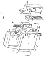
- Fig. 17 is a sectional view showing a plug and the socket
- Fig. 17 (A) a fragmentary sectional view of the plug
- Fig. 17 (B) a sectional view of the socket, showing a state prior to the socket provided with a pair of shutters being coupled up with the plug.
- a pair of shutters 210a, 210b are urged to an inlet side of a plug hole 202 by elastic members 240a, 240b, respectively, and consequently, the inlet side of the plug hole 202 is blocked up with the pair of the shutters 210a, 210b.
- the plug extremity 106 Upon further pushing the plug 100 forward, the plug extremity 106 is inserted into a hole 204 defined in a protruded part 205 provided in the innermost part of the plug hole 202, and is held therein. Upon the insertion of the plug extremity 106 in the hole 204, the tip of an optical fiber 107 is butted against, or brought close to an optical device 300, whereupon transmit / receipt of optical signals is executed.
- reference numeral 101 denotes a plug main body, 103 an engaging protuberance, 105 recesses, and 109 protrusions. When the plug is coupled up with the socket, the protrusions 109 are fitted into socket recesses 206, respectively, and the plug extremity 106 is stably held.
- the shutter 210A in a horizontal posture is housed in a room 260A of the plug hole 202A, and the plug extremity 106A is inserted into a hole 204A defined in a protruded part 205A provided in the innermost part of the plug hole 202A, and is held therein.
- the plug hole 202A needs to be provided with space 250A for allowing the engaging protuberance 103A of the plug 100A to be inserted therein, and the room 260A extended from the space 250A, sufficient for housing the shutter 210A in the horizontal posture therein.
- the depth dimension of the plug hole 202A needs to be slightly larger than the height dimension of the shutter 210A. Accordingly, portions of the space 250A, indicated by a dash and double-dotted line in Fig. 18 (B), become obstructive, and need to be removed at the time of molding.
- the protruded part 205A, the innermost sidewall, and inner walls of the space 250A need to be shaved off in order to enlarge portions of cavity, in the innermost part of the plug hole 202A.
- a risk of retention of the plug extremity 106A being destabilized due to a shortened length of the protruded part 205A, and a resultant decrease in the depth of the hole 204A.
- a change in specification in this aspect, is required to be adapted to the EIAJ specification.
- Another object of the invention is to provide a socket for a connector, simple in construction, wherein the number of components constituting the socket is reduced, so that assembling is effected with ease.
- Still another object of the invention is to provide a socket for a connector, simple in construction, wherein the number of components constituting the socket is reduced, so that replacement, repair, and so forth of the components as well as assembling is effected with ease.
- Yet another object of the invention is to provide a socket for a connector, capable of preventing foreign matter such as dust, and so forth from making ingress therein, and eliminating leakage of light to the outside thereof without deviating from the EIAJ specification.
- the socket housing can be applied to the plug for the optical connector without changing an EIAJ specification.
- the configuration of the narrow opening is easily molded for allowing the components constituting the socket to be inserted and set therethrough, thereby simplifying the assembly.
- the configuration of the narrow opening is easily molded and the components constituting the socket can be inserted and set through the narrow opening, thereby simplifying the assembly. Further, since the components are set on the cover body, thereby more simplifying the assembly.
- a socket for an optical connector according to first to third embodiments of the invention is described hereinafter.
- the invention is not limited to a socket for an optical connector but can be also used as a general electric connector.
- the depth of the narrow opening 30, namely, the depth directing from the rear face 14 to the front face 13 is set at a length capable of reaching substantially the center of the socket housing 10, while the length of the narrow opening 30 in the vertical direction is set such that it extends from the portion immediately under the fixing hole 45 to the bottom face 12, and the lower end of the narrow opening 30 is opened.
- the entire shape of the narrow opening 30 is a substantially tunnel-like shape as viewed from the inlet thereof. Since the narrow opening 30 is opened at the rear face 14 and bottom face 12 to have a substantially tunnel-like shape, a mold thereof is simplified and the molding becomes easy at the time of molding.
- the inclined angle of the inclined face 58 is an angle to an extent that when the plug extremity is butted against the inclined face 58 strong, the plug extremity slides on the inclined face to press the inclined face 58 to push up the shutter 50 so that the shutter 50 can smoothly move.
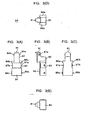
- the shapes of the hole 57 having a bottom and the inclined face 58 of the shutter 50 are respectively illustrated in detail in Fig. 4(A) to Fig. 4(D). The chamfer of the respective corners of the walls in Fig. 4(D) is omitted.
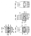
- the socket housing 10 includes a cavity 20, for allowing a plug, described later, to be inserted therein, there is the front face 13 thereof, a protuberance 23 provided in the cavity 20 at the innermost part and a through hole 22 formed at the center of the protuberance 23.
- the through hole 22 has outer end having a size to the extent for allowing a plug extremity to be inserted therein so as to be held thereby, and the other end opposite to the optical element 70.
- One end of the elastic member 60 is inserted into the hole 57 having the bottom of the shutter 50, causing the shutter 50 to be assembled. Then the shutter 50 is inserted through the inclined face 58 into the opening 24 for allowing both the shutter 50 and the elastic member 60 to be disposed therein perpendicularly (see Fig. 6(B)). Further, the optical element 70 is inserted into the narrow opening 30 and finally the cover body 80 is fitted in the narrow opening 30. When the cover body 80 is fitted in the narrow opening 30, the shutter 50, the elastic member 60, the optical element 70 are respectively positioned in and fixed to the narrow opening 30 (see Fig. 6(D)).
- the shutter 50 is further moved upward so that the extremity 56a of the shutter 50 is placed on the plug extremity 106 and the tip end of optical fiber 107 is brought close to or butted against the light receiving or light emitting face 72 of the optical element 70 at the same time (see Fig. 7(C)). Conversely, if the plug 100 is pulled out from the opening, the shutter 50 is lowered owing to the urging force of the elastic member 60 so that the front face of the optical element 70 is blocked up to return to the original state (see Fig. 7(A)).
- the opening is not limited to this position and may be formed on one wall disposed either right and left in the lateral direction of the through hole or downward in the vertical direction of the same.
- the shutter is differentiated in the insertion direction or movement direction but not differentiated in function.
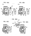
- the cover body 80A covers the narrow opening 30A of the socket housing 10A and has the same shape as the narrow opening 30A for allowing the narrow opening 30A to be fitted, engaged and set therein. That is, the entire shape of the cover body 80A is long and rectangular parallelepiped and has a guide protrusion 81A provided at the head thereof for allowing the groove of the narrow opening 30A to be set and guided thereby, and a pair of protrusions 86Aa, 86Ab provided at the neck thereof for allowing the same groove to be fitted thereby, and a groove 89 extending from the barrel to the hip for allowing the optical element 70A to be fitted thereinto.
- the configuration of the groove 89 comprises a room for allowing the head of the optical element 70A to be fitted thereinto and grooves 89Aa to 89Ac for allowing the terminals of the optical element 70A to be fitted thereinto.
- the pair of shutters 50Aa, 50Ab are positioned. Since the inclined face 58A of the shutter 50Ab has the protrusion piece 59A, the protrusion piece 59A is brought into contact under pressure with the inclined face 58Aa of the other shutter 50Aa in a state where the ends of the inclined faces 56Aa, 56Ab of the pair of shutters 50Aa, 50Ab are jointed with each other, thereby blocking up the through hole completely.
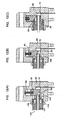
- the optical element 70B is set in the groove 89B of the cover body 80B. Thereafter, the cover body 80B in which the optical element 70B is set is fitted into the narrow opening 30B (see Fig.16(A), Fig.16(B)).
- the coupling or connection and non-coupling or disconnection between the socket and the plug according to the third embodiment are the same as those according to the second embodiment except the moving direction of the shutters, namely, they move horizontally in the third embodiment while they move vertically in the second embodiment.
- the molding of the socket housing constituting the socket becomes easy, and the pair of shutters are separated from each other, the closing operation of the shutter mechanism is speeded up compared with that using a single shutter, and further, since the optical element is set in the cover body, the assembling of the components in the socket housing is simplified.
Landscapes
- Physics & Mathematics (AREA)
- General Physics & Mathematics (AREA)
- Optics & Photonics (AREA)
- Mechanical Coupling Of Light Guides (AREA)
- Connector Housings Or Holding Contact Members (AREA)
- Optical Couplings Of Light Guides (AREA)
- Manufacturing Of Electrical Connectors (AREA)
Claims (13)
- Réceptacle pour connecteur comprenant une cavité (20) destinée à permettre qu'une fiche (100, 100A) y soit insérée, une protubérance (23) prévue à l'intérieur de la cavité (20), un trou traversant (22) défini sensiblement au centre de la protubérance (23) destiné à permettre qu'une extrémité de fiche (106, 106A) soit insérée depuis une extrémité extérieure de celui-ci, et un élément de connecteur (70, 70A) disposé au niveau d'une extrémité intérieure du trou traversant (22), opposé à celui-ci, où le trou traversant (22) est bloqué vers le haut par un obturateur (50) par le biais d'une force de sollicitation d'un élément élastique (60) alors que le trou traversant (22) est libéré d'un état bloqué lors de l'insertion de la fiche (100), caractérisé en ce qu'une ouverture (24) est définie dans une paroi (15) du trou traversant (22) en découpant une partie de la paroi (15), où l'obturateur (50) est inséré dans l'ouverture (24).
- Réceptacle pour connecteur selon la revendication 1, dans lequel l'ouverture (24) est définie dans la paroi (15) s'étendant soit à droite et à gauche dans la direction horizontale, soit vers le haut et vers le bas dans la direction verticale.
- Réceptacle pour connecteur selon la revendication 1 ou 2, une face inclinée (58) est formée sur une première face d'extrémité de l'obturateur (50) et lorsqu'une extrémité de la face inclinée (58) est en butée contre le trou traversant (22), le trou traversant est bloqué par l'obturateur (50) alors que, lorsque la face inclinée (58) est pressée par l'extrémité de fiche (106), l'obturateur (50) est déplacé contre la force de sollicitation de l'élément élastique (60) afin de libérer le trou traversant (22) à l'état bloqué.
- Réceptacle pour connecteur selon la revendication 3, dans lequel une rainure (26a, 26b) ou un épaulement (25) est défini au niveau de la partie où l'extrémité inclinée (56a) de l'obturateur (50) est en butée contre la face intérieure du trou traversant (22), ce qui amène l'extrémité inclinée (56a) de l'obturateur (50) à effectuer une entrée dans la rainure (26a, 26b) ou à être en butée contre l'épaulement (25).
- Réceptacle pour connecteur selon l'une quelconque des revendications précédentes, comprenant deux obturateurs (50Aa, 50Ab) qui sont insérés dans l'ouverture (24A), les premières extrémités des obturateurs respectifs (50Aa, 50Ab) sont sollicitées par des éléments élastiques (60Aa, 60Ab) alors que les autres extrémités des obturateurs respectifs (50Aa, 50Ab) sont amenées en contact l'une avec l'autre afin de bloquer vers le haut le trou traversant (22A) et le trou traversant est libéré d'un état bloqué dans une insertion de la fiche.
- Réceptacle pour connecteur selon la revendication 5, dans lequel l'ouverture (24A) est définie dans les parois des trous traversants (22A) en découpant une partie des parois disposées en face d'une extrémité intérieure du trou traversant (22A) dans la direction verticale.
- Réceptacle pour connecteur selon la revendication 5, dans lequel une ouverture (24B) est définie dans les parois d'un trou traversant (22B) en découpant une partie des parois disposées de manière opposée au niveau d'une extrémité intérieure du trou traversant (22B) dans la direction horizontale.
- Réceptacle pour connecteur selon l'une quelconque des revendications 5 à 7, dans lequel les faces inclinées (58Aa, 58Ab, 58Ba, 58Bb) sont formées sur les premières faces d'extrémité des obturateurs (50Aa, 50Ab, 50Ba, 50Bb) tout en laissant des extrémités (56Aa, 56Ab, 56Ba, 56Bb) des obturateurs (50Aa, 50Ab, 50Ba, 50Bb) sur les premières faces d'extrémité par le biais d'une petite partie, et lorsque les extrémités (56Aa, 56Ab, 56Ba, 56Bb) des obturateurs (50Aa, 50Ab, 50Ba, 50Bb) sont en butée les unes contre les autres, le trou traversant (22A, 22B) est bloqué vers le haut avec les obturateurs (50Aa, 50Ab, 50Ba, 50Bb), alors que lorsque les faces inclinées (58Aa, 58Ab, 58Ba, 58Bb) sont pressées par l'extrémité d'une fiche (106A), les obturateurs (50Aa, 50Ab, 50Ba, 50Bb) sont déplacés en s'opposant à la force de sollicitation de l'élément élastique (60Aa, 60Ab, 60Ba, 60Bb) afin de libérer le trou traversant (22A, 22B) d'un état bloqué.
- Réceptacle pour connecteur selon la revendication 8, dans lequel un élément de protubérance (59A, 59B) présentant une certaine élasticité est prévu sur l'extrémité de bout d'une face inclinée (58Ab, 58Bb), où, lorsque les extrémités (56Aa, 56Ab, 56Ba, 56Bb) des obturateurs (50Aa, 50Ab, 50Ba, 50Bb) sont amenées en contact les unes avec les autres, l'élément de protubérance (59A, 59B) est amené en contact élastique avec l'autre face inclinée (58Ab, 58Bb) pour bloquer vers le haut le trou traversant (22A, 22B).
- Réceptacle pour connecteur selon l'une quelconque des revendications 1 à 9, dans lequel la fiche (100, 100A) est une fiche pour un connecteur optique et l'élément connecteur (70, 70A, 70B) est un élément optique.
- Réceptacle pour connecteur selon l'une quelconque des revendications 1 à 9, dans lequel la fiche (100, 100A) est une fiche pour un connecteur électrique et l'élément connecteur (70, 70A, 70B) est un élément connecteur électrique.
- Procédé d'assemblage d'un réceptacle pour connecteur selon l'une quelconque des revendications précédentes, comprenant l'utilisation d'un réceptacle définissant une ouverture étroite dans la face arrière d'un logement de réceptacle (10, 10A, 10B) pour permettre qu'un obturateur (50) ou des obturateurs (50Aa, 50Ab, 50Ba, 50Bb) et des composants (70, 70A, 70B) y soient insérés et un corps de couvercle (80, 80A, 80B) y soient insérés, en amenant l'obturateur (50) ou les obturateurs (50Aa, 50Ab, 50Ba, 50Bb) et les composants (70, 70A, 70B) à y être fixés.
- Procédé d'assemblage d'un réceptacle pour connecteur selon l'une quelconque des revendications précédentes, comprenant l'utilisation d'un réceptacle définissant une ouverture étroite dans la face arrière d'un logement de réceptacle, le fait de placer des composants (70, 70A, 70B) sur la face avant d'un corps de couvercle (80, 80A, 80B) pour permettre qu'un obturateur (50) ou des obturateurs (50Aa, 50Ab, 50Ba, 50Bb) soient insérés dans l'ouverture étroite et pour permettre que le couvercle (80, 80A, 80B) soit ajusté sur l'ouverture étroite, en amenant l'obturateur (50) ou les obturateurs (50Aa, 50Ab, 50Ba, 50Bb) à y être fixés.
Applications Claiming Priority (2)
| Application Number | Priority Date | Filing Date | Title |
|---|---|---|---|
| JP2001057483A JP2002260774A (ja) | 2001-03-01 | 2001-03-01 | コネクタ用ソケット及びその組立て方法 |
| JP2001057483 | 2001-03-01 |
Publications (2)
| Publication Number | Publication Date |
|---|---|
| EP1237231A1 EP1237231A1 (fr) | 2002-09-04 |
| EP1237231B1 true EP1237231B1 (fr) | 2006-12-27 |
Family
ID=18917350
Family Applications (1)
| Application Number | Title | Priority Date | Filing Date |
|---|---|---|---|
| EP02004525A Expired - Lifetime EP1237231B1 (fr) | 2001-03-01 | 2002-02-27 | Réceptacle pour connecteur |
Country Status (7)
| Country | Link |
|---|---|
| US (1) | US6793402B2 (fr) |
| EP (1) | EP1237231B1 (fr) |
| JP (1) | JP2002260774A (fr) |
| KR (1) | KR100871530B1 (fr) |
| CN (1) | CN1229663C (fr) |
| DE (1) | DE60216993T2 (fr) |
| TW (1) | TW556370B (fr) |
Families Citing this family (16)
| Publication number | Priority date | Publication date | Assignee | Title |
|---|---|---|---|---|
| JPWO2004063785A1 (ja) * | 2003-01-10 | 2006-05-18 | 日本圧着端子製造株式会社 | 光リセプタクル |
| JP4074835B2 (ja) * | 2003-05-29 | 2008-04-16 | 日本圧着端子製造株式会社 | 光リセプタクル |
| JP2005077989A (ja) * | 2003-09-03 | 2005-03-24 | Jst Mfg Co Ltd | コネクタ装置 |
| WO2005106552A1 (fr) * | 2004-04-28 | 2005-11-10 | Honda Tsushin Kogyo Co., Ltd | Structure de raccord de connecteur optique et fiche de connecteur optique et dispositif optique comportant cette structure de raccord |
| KR100812775B1 (ko) | 2006-08-18 | 2008-03-12 | (주)대영오앤이 | Ccfl을 pcb 기판에 고정하기 위한 소켓의 하우징 |
| CN101212548B (zh) | 2006-12-31 | 2010-05-19 | 北京爱国者妙笔数码科技有限责任公司 | 利用点读操控装置操控电视机顶盒的系统 |
| CN101854007B (zh) * | 2009-04-02 | 2012-08-29 | 富士康(昆山)电脑接插件有限公司 | 电连接器 |
| TWI420759B (zh) * | 2009-04-03 | 2013-12-21 | Hon Hai Prec Ind Co Ltd | 電連接器 |
| CN101872041B (zh) * | 2009-04-27 | 2012-08-29 | 富士康(昆山)电脑接插件有限公司 | 光电连接器 |
| US8579518B2 (en) * | 2010-03-19 | 2013-11-12 | Corning Incorporated | Optical receptacles and systems and devices including optical receptacles |
| US8727636B2 (en) * | 2010-03-19 | 2014-05-20 | Corning Incorporated | Fiber optic interface device with positionable cleaning cover |
| JP5080624B2 (ja) * | 2010-08-31 | 2012-11-21 | 日本航空電子工業株式会社 | 光電複合コネクタ及びそのレセプタクル |
| JP2013125219A (ja) * | 2011-12-15 | 2013-06-24 | Kel Corp | 光コネクタ装置 |
| JP5541637B2 (ja) * | 2012-03-21 | 2014-07-09 | サミー株式会社 | 光ファイバコネクタ |
| TWI600228B (zh) * | 2017-01-10 | 2017-09-21 | Pei-Lin Huang | Socket structure |
| CN115425451A (zh) * | 2021-05-13 | 2022-12-02 | 深南电路股份有限公司 | 一种遮挡组件及其线缆适配器 |
Citations (1)
| Publication number | Priority date | Publication date | Assignee | Title |
|---|---|---|---|---|
| JP2000131564A (ja) * | 1998-04-20 | 2000-05-12 | Hosiden Corp | 光コネクタのソケット |
Family Cites Families (12)
| Publication number | Priority date | Publication date | Assignee | Title |
|---|---|---|---|---|
| DE2315569C3 (de) * | 1973-03-28 | 1980-01-24 | Siemens Ag, 1000 Berlin Und 8000 Muenchen | Verschluß für ein Kontaktfedern enthaltendes Gehäuse |
| JPS5033292U (fr) * | 1973-07-21 | 1975-04-10 | ||
| US4379607A (en) * | 1980-10-06 | 1983-04-12 | Slater Electric Inc. | Shuttered receptacle |
| US4544219A (en) * | 1984-06-01 | 1985-10-01 | Harvey Hubbell Incorporated | Shuttered electrical receptacle |
| IT1230054B (it) * | 1989-07-05 | 1991-09-27 | Bassani Spa | Dispositivo di sicurezza per la protezione degli alveoli di una presa di corrente elettrica. |
| JPH09178976A (ja) * | 1995-12-22 | 1997-07-11 | Matsushita Electric Ind Co Ltd | 光コネクタ |
| KR200192441Y1 (ko) * | 1997-03-15 | 2000-09-01 | 한영희 | 콘센트 안전장치 |
| JP3263629B2 (ja) * | 1997-06-19 | 2002-03-04 | 三洋電機株式会社 | 電子機器コネクタ |
| US5967815A (en) * | 1998-03-19 | 1999-10-19 | Marc A. Schlessinger | Variable orientation switching type electrical receptacle |
| DE19919591C2 (de) * | 1999-04-29 | 2001-12-20 | Tyco Electronics Logistics Ag | Steckverbindung für Lichtwellenleiter |
| US6217353B1 (en) * | 1999-12-01 | 2001-04-17 | Aurise Inc. | Structure of a safety receptacle |
| KR20010084128A (ko) * | 2000-02-24 | 2001-09-06 | 이장우 | 콘센트 |
-
2001
- 2001-03-01 JP JP2001057483A patent/JP2002260774A/ja active Pending
-
2002
- 2002-02-21 KR KR1020020009278A patent/KR100871530B1/ko not_active Expired - Fee Related
- 2002-02-25 TW TW091103272A patent/TW556370B/zh not_active IP Right Cessation
- 2002-02-27 US US10/083,509 patent/US6793402B2/en not_active Expired - Fee Related
- 2002-02-27 EP EP02004525A patent/EP1237231B1/fr not_active Expired - Lifetime
- 2002-02-27 DE DE60216993T patent/DE60216993T2/de not_active Expired - Lifetime
- 2002-02-28 CN CNB021065896A patent/CN1229663C/zh not_active Expired - Fee Related
Patent Citations (1)
| Publication number | Priority date | Publication date | Assignee | Title |
|---|---|---|---|---|
| JP2000131564A (ja) * | 1998-04-20 | 2000-05-12 | Hosiden Corp | 光コネクタのソケット |
Also Published As
| Publication number | Publication date |
|---|---|
| KR100871530B1 (ko) | 2008-12-05 |
| EP1237231A1 (fr) | 2002-09-04 |
| TW556370B (en) | 2003-10-01 |
| US6793402B2 (en) | 2004-09-21 |
| CN1229663C (zh) | 2005-11-30 |
| KR20020070803A (ko) | 2002-09-11 |
| US20020122633A1 (en) | 2002-09-05 |
| CN1374541A (zh) | 2002-10-16 |
| DE60216993D1 (de) | 2007-02-08 |
| DE60216993T2 (de) | 2007-05-10 |
| JP2002260774A (ja) | 2002-09-13 |
Similar Documents
| Publication | Publication Date | Title |
|---|---|---|
| EP1237231B1 (fr) | Réceptacle pour connecteur | |
| EP3327476B1 (fr) | Adaptateur de fibre optique ayant des éléments d'obturation | |
| US9804340B1 (en) | Optical fiber connector capable of switching connection polarity | |
| US9279940B2 (en) | Optical fiber adapter with shutter member | |
| JPH11326694A (ja) | 光ファイバコネクタ組立体 | |
| JP3654063B2 (ja) | 光コネクタ | |
| WO2008029850A1 (fr) | Connecteur optique | |
| US5919056A (en) | Connector disengaging mechanism | |
| US6652152B2 (en) | Optical fiber connector | |
| JP3307846B2 (ja) | コネクタ | |
| JPH11305070A (ja) | 光ファイバコネクタ | |
| JP2012037652A (ja) | 光コネクタ、取り外し治具、及び光コネクタの取り外し構造 | |
| JP2002329554A (ja) | コネクタ | |
| US6341974B1 (en) | Connector with a partial connection preventing function | |
| EP0716478B1 (fr) | Structure et procédé de connexion électrique | |
| EP1001289B1 (fr) | Connecteur optique à sécurité intégré | |
| KR100381573B1 (ko) | 캠부재를가지는전기커넥터 | |
| JPH10241801A (ja) | 分割コネクタ | |
| JPH07249454A (ja) | コネクタ | |
| JP2002324614A (ja) | コネクタ | |
| US6004147A (en) | Line terminal particularly signal transmitter, connector assembly | |
| JPH11204184A (ja) | コンタクト保持装置付き電気コネクタ | |
| JP3779901B2 (ja) | 光コネクタ用ハウジング及び光コネクタ | |
| JPH07130428A (ja) | コネクタ | |
| JPH0812310B2 (ja) | 光コネクタプラグ |
Legal Events
| Date | Code | Title | Description |
|---|---|---|---|
| PUAI | Public reference made under article 153(3) epc to a published international application that has entered the european phase |
Free format text: ORIGINAL CODE: 0009012 |
|
| AK | Designated contracting states |
Kind code of ref document: A1 Designated state(s): AT BE CH CY DE DK ES FI FR GB GR IE IT LI LU MC NL PT SE TR |
|
| AX | Request for extension of the european patent |
Free format text: AL;LT;LV;MK;RO;SI |
|
| 17P | Request for examination filed |
Effective date: 20030204 |
|
| AKX | Designation fees paid |
Designated state(s): DE FR GB |
|
| GRAP | Despatch of communication of intention to grant a patent |
Free format text: ORIGINAL CODE: EPIDOSNIGR1 |
|
| GRAS | Grant fee paid |
Free format text: ORIGINAL CODE: EPIDOSNIGR3 |
|
| GRAA | (expected) grant |
Free format text: ORIGINAL CODE: 0009210 |
|
| RAP1 | Party data changed (applicant data changed or rights of an application transferred) |
Owner name: J.S.T. MFG. CO., LTD. |
|
| AK | Designated contracting states |
Kind code of ref document: B1 Designated state(s): DE FR GB |
|
| REG | Reference to a national code |
Ref country code: GB Ref legal event code: FG4D |
|
| REF | Corresponds to: |
Ref document number: 60216993 Country of ref document: DE Date of ref document: 20070208 Kind code of ref document: P |
|
| ET | Fr: translation filed | ||
| PLBE | No opposition filed within time limit |
Free format text: ORIGINAL CODE: 0009261 |
|
| STAA | Information on the status of an ep patent application or granted ep patent |
Free format text: STATUS: NO OPPOSITION FILED WITHIN TIME LIMIT |
|
| 26N | No opposition filed |
Effective date: 20070928 |
|
| PGFP | Annual fee paid to national office [announced via postgrant information from national office to epo] |
Ref country code: FR Payment date: 20090213 Year of fee payment: 8 |
|
| PGFP | Annual fee paid to national office [announced via postgrant information from national office to epo] |
Ref country code: DE Payment date: 20100312 Year of fee payment: 9 Ref country code: GB Payment date: 20100224 Year of fee payment: 9 |
|
| REG | Reference to a national code |
Ref country code: FR Ref legal event code: ST Effective date: 20101029 |
|
| PG25 | Lapsed in a contracting state [announced via postgrant information from national office to epo] |
Ref country code: FR Free format text: LAPSE BECAUSE OF NON-PAYMENT OF DUE FEES Effective date: 20100301 |
|
| GBPC | Gb: european patent ceased through non-payment of renewal fee |
Effective date: 20110227 |
|
| REG | Reference to a national code |
Ref country code: DE Ref legal event code: R119 Ref document number: 60216993 Country of ref document: DE Effective date: 20110901 |
|
| PG25 | Lapsed in a contracting state [announced via postgrant information from national office to epo] |
Ref country code: GB Free format text: LAPSE BECAUSE OF NON-PAYMENT OF DUE FEES Effective date: 20110227 |
|
| PG25 | Lapsed in a contracting state [announced via postgrant information from national office to epo] |
Ref country code: DE Free format text: LAPSE BECAUSE OF NON-PAYMENT OF DUE FEES Effective date: 20110901 |