EP0716478B1 - Structure et procédé de connexion électrique - Google Patents
Structure et procédé de connexion électrique Download PDFInfo
- Publication number
- EP0716478B1 EP0716478B1 EP95119241A EP95119241A EP0716478B1 EP 0716478 B1 EP0716478 B1 EP 0716478B1 EP 95119241 A EP95119241 A EP 95119241A EP 95119241 A EP95119241 A EP 95119241A EP 0716478 B1 EP0716478 B1 EP 0716478B1
- Authority
- EP
- European Patent Office
- Prior art keywords
- connector
- female connector
- female
- male
- male connector
- Prior art date
- Legal status (The legal status is an assumption and is not a legal conclusion. Google has not performed a legal analysis and makes no representation as to the accuracy of the status listed.)
- Expired - Lifetime
Links
Images


Classifications
-
- H—ELECTRICITY
- H01—ELECTRIC ELEMENTS
- H01R—ELECTRICALLY-CONDUCTIVE CONNECTIONS; STRUCTURAL ASSOCIATIONS OF A PLURALITY OF MUTUALLY-INSULATED ELECTRICAL CONNECTING ELEMENTS; COUPLING DEVICES; CURRENT COLLECTORS
- H01R13/00—Details of coupling devices of the kinds covered by groups H01R12/70 or H01R24/00 - H01R33/00
- H01R13/02—Contact members
- H01R13/193—Means for increasing contact pressure at the end of engagement of coupling part, e.g. zero insertion force or no friction
-
- H—ELECTRICITY
- H01—ELECTRIC ELEMENTS
- H01R—ELECTRICALLY-CONDUCTIVE CONNECTIONS; STRUCTURAL ASSOCIATIONS OF A PLURALITY OF MUTUALLY-INSULATED ELECTRICAL CONNECTING ELEMENTS; COUPLING DEVICES; CURRENT COLLECTORS
- H01R24/00—Two-part coupling devices, or either of their cooperating parts, characterised by their overall structure
-
- H—ELECTRICITY
- H01—ELECTRIC ELEMENTS
- H01R—ELECTRICALLY-CONDUCTIVE CONNECTIONS; STRUCTURAL ASSOCIATIONS OF A PLURALITY OF MUTUALLY-INSULATED ELECTRICAL CONNECTING ELEMENTS; COUPLING DEVICES; CURRENT COLLECTORS
- H01R13/00—Details of coupling devices of the kinds covered by groups H01R12/70 or H01R24/00 - H01R33/00
- H01R13/62—Means for facilitating engagement or disengagement of coupling parts or for holding them in engagement
- H01R13/629—Additional means for facilitating engagement or disengagement of coupling parts, e.g. aligning or guiding means, levers, gas pressure electrical locking indicators, manufacturing tolerances
-
- H—ELECTRICITY
- H01—ELECTRIC ELEMENTS
- H01R—ELECTRICALLY-CONDUCTIVE CONNECTIONS; STRUCTURAL ASSOCIATIONS OF A PLURALITY OF MUTUALLY-INSULATED ELECTRICAL CONNECTING ELEMENTS; COUPLING DEVICES; CURRENT COLLECTORS
- H01R13/00—Details of coupling devices of the kinds covered by groups H01R12/70 or H01R24/00 - H01R33/00
- H01R13/62—Means for facilitating engagement or disengagement of coupling parts or for holding them in engagement
- H01R13/627—Snap or like fastening
- H01R13/6271—Latching means integral with the housing
- H01R13/6272—Latching means integral with the housing comprising a single latching arm
-
- H—ELECTRICITY
- H01—ELECTRIC ELEMENTS
- H01R—ELECTRICALLY-CONDUCTIVE CONNECTIONS; STRUCTURAL ASSOCIATIONS OF A PLURALITY OF MUTUALLY-INSULATED ELECTRICAL CONNECTING ELEMENTS; COUPLING DEVICES; CURRENT COLLECTORS
- H01R24/00—Two-part coupling devices, or either of their cooperating parts, characterised by their overall structure
- H01R24/66—Two-part coupling devices, or either of their cooperating parts, characterised by their overall structure with pins, blades or analogous contacts and secured to apparatus or structure, e.g. to a wall
Definitions
- the present invention relates to an electrical connection structure for connectors, and more particularly to an electrical connection structure suited for use when space for fitting connectors together is limited.
- a connector device for direct connection to a motor which is mounted, for example, on a drive portion of a power window of an automobile.
- This connector device is mounted on a housing having, at a motor output shaft-side, receiving portions within which an output shaft of the motor and speed reduction gears that engage the output shaft are mounted, respectively.
- a pair of male metal terminals connected to a brush of the motor, are mounted tab portions of the male metal terminals parallel to the output shaft of the motor, thus constituting a male connector.
- a mating female connector within which female metal terminals are disposed is adapted to be fitted on the male connector.
- the female connector When the female connector is to be fitted on the male connector, the female connector is usually aligned with the male connector from a side towards which a front end of each tab portion is directed.
- mounting legs for mounting the housing on a body project in front of the tab portion. As a result, the fitting space is so limited that the connector-fitting operation can not be completed easily.
- US-A-5,167,520 teaches a coaxial electrical connector comprising a multiple-sectioned, one piece shell of a coupling body having a larger outside diameter cup-shaped front section with outwardly flared annular lip, and a second intermediate sleeve form section of a smaller outside diameter than the diameter of the front section.
- an object of the invention is to provide an electrical connection structure in which even if a connector-fitting space is limited, female and male metal terminals can be fitted together with a large area of contact therebetween without lowering the efficiency of the fitting operation.
- Another object of the invention is to provide a construction in which a mating connector can be guided with a simple construction.
- Still another object of the invention is to provide a construction in which a mating connector can be moved without shaking so that metal terminals can be connected together without gouging.
- Yet another object of the invention is to provide a construction in which two connectors, when fitted together, are locked against easy disengagement.
- the guiding portion includes a guide plate attached to the other connector and a guide plate groove shaped to receive the guide plate formed in the guided connector.
- the guided connector is preferably disposed relative to the other connector such that the guiding direction is substantially perpendicular to the normal axis extending from the terminal side of the other connector.
- the guiding portion includes a limitation portion and the guided connector includes a guide groove shaped to receive the limitation portion in the alignment position. As a result, the limitation portion engages the guide groove when the male connector and the female connector are urged together.
- the guide groove preferably extends approximately perpendicular to the guiding direction such that engagement between the guide groove and the limitation portion prevents movement of the guided connector in the guiding direction.
- the electrical connector assembly preferably includes a locking mechanism that locks the male connector and the female connector to each other when the male connector and the female connector in the alignment position are urged towards each other.
- the locking mechanism preferably includes locking members attached to the male connector and corresponding locking members attached to the female connector. The locking members are disposed to engage the corresponding locking members when the male connector and the female connector in the alignment position are urged towards each other.
- the guiding portion preferably includes a guide plate that projects by a first height from the terminal side between the terminals of either the male connector or the female connector.
- the guided connector preferably includes a guide plate groove that extends in the guiding direction and is shaped to receive the guide plate.
- the guide plate preferably includes guide surfaces disposed on at least one side of the guide plate at a second height less than the first height, the guide surface surfaces slidably supporting the guided one of the male connector and the female connector.
- the guide surface is preferably includes limitation portions that pertrude outward from the guide plate in a direction approximately perpendicular to the guiding direction.
- the positioning portion preferably includes a positioning member shaped contact the housing of the guided connector.
- the positioning portion is preferably an abutment wall that contacts the guided connector.
- the abutment wall is preferably disposed approximately parallel to the terminals of and perpendicular to the terminal side of the other connector.
- the terminals of the female connector are preferably L-shaped and include female terminal end portions disposed approximately perpendicular to female terminal wire connection portions.
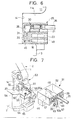
- Figs. 1 to 6 show a first embodiment of the invention.
- a housing 2 is mounted on one end portion of a motor 1 from which a motor output shaft is projected.
- the housing 2 is molded of a synthetic resin in a single piece.
- a mounting portion 3 of this housing is mated with and fastened to a mounting flange 4 of the motor 1 by screws 5, and covers the mounting-side end of the motor 1.
- the housing 2 has an output shaft-receiving portion 7 in which the output shaft of the motor 1 is rotatably received, the output shaft-receiving portion 7 being in communication with the mounting portion 3.
- a gear receiving portion 8 is formed on one side of the output shaft-receiving portion 7, and a gear, meshed with a worm gear formed on the output shaft, is rotatably received by the gear receiving portion 8.
- Three mounting legs 9,10,11 are formed on the outer periphery of the gear receiving portion 8 at spaced intervals extending in a radial direction.
- the two mounting legs 9 and 10 are disposed generally at the top and bottom of the gear mounting portion 8, respectively, and the other mounting leg 11 extends in a direction away from the gear receiving portion 8 to project across the output shaft-receiving portion 7.
- a mounting hole 12 is formed through a distal end of each of the mounting legs 9,10,11.
- the housing 2 is fastened to a fixing member, such as a vehicle body, by screws passing respectively through the mounting holes 12.
- An abutment wall 14 is formed between the lower surface of the mounting leg 11 and the upper surface of the mounting portion 3, and is disposed adjacent to the output shaft-receiving portion 7.
- the abutment wall extends approximately parallel to the output shaft-receiving portion 7.
- a male connector 15 is formed at the outer side of the abutment wall 14.
- two holes 17, which are elongate in a direction perpendicular to the abutment wall 14, are formed in a bottom surface 16 (defined by the upper surface of the mounting portion 3) of the male connector 15, and are disposed adjacent to an outer surface of the abutment wall 14.
- the two holes 17 are spaced by a predetermined distance from each other in a direction parallel to the abutment wall 14.
- a pair of male metal terminals 19, connected to a brush (not shown) of the motor 1, are provided at the bottom surface 16 of the male connector 15 such that a tab portion 20 of each terminal 19 projects upwardly through the associated hole 17 by a predetermined distance from the bottom surface 16.
- a guide plate 21 is formed integrally on that portion of the bottom surface 16 of the male connector 15 disposed intermediate the two tab portions 20, and extends perpendicularly to the abutment wall 14.
- the guide plate 21 extends upwardly to a height or level generally equal to that of the upper ends of the tab portions 20.
- the guide plate 21 has such a length that it projects by a predetermined distance outwardly from the peripheral edge of the bottom surface 16.
- a pair of limitation portions 22 are formed respectively on opposite sides of that portion of the guide plate 21 projecting outwardly from the bottom surface 16.
- the limitation portions 22 have a flat, rectangular parallelepiped shape, and their upper surfaces serve as sliding surfaces 23 parallel to the bottom surface 16 of the male connector 15. More specifically, a bottom surface of a mating female connector 25 (described below) can be brought into sliding contact with the sliding surfaces 23 of the limitation portions 22 so that the female connector 25 can be pushed in parallel relation to the bottom surface 16 of the male connector 15.
- the dimension between the sliding surface 23 of each limitation portion 22 and a lower surface 11a of the mounting leg 11 is generally equal to the height of the female connector 25 (see Fig. 4).
- a reinforcing portion 24 of a larger thickness extends from the outer peripheral surface of the mounting portion 3, and is integrally formed on the lower surface of that portion of the guide plate 21 projecting outwardly from the peripheral edge of the bottom surface 16 of the male connector 15 to support the projecting portion.
- the female connector 25 includes a housing 26 fabricated of a synthetic resin.
- the housing 26 includes a body portion 27 and a lid portion 28 which is fitted on the body portion 27 such that the lid portion 28 covers an upper surface of the body portion 27, opposite (right and left) side surfaces thereof and an upper portion of a front surface thereof.
- the housing 26 has a generally rectangular parallelepiped shape, as shown in Figs. 2 and 3.
- the housing 26 of the female connector 25 has a height dimensioned such that the housing 26 can be inserted between the sliding surfaces 23 of the limitation portions 22 and the lower surface 11a of the mounting leg 11.
- the housing 26 is slightly larger in length than the guide plate 21, as shown in Fig. 5.
- a pair of female metal terminals 30 for fitting respectively on the tab portions 20 of the male metal terminals 19 are disposed within the housing 26.
- the female metal terminal 30 is generally L-shaped as shown in Fig. 4, and opposite side edge portions of its front end portion are folded to form a connection portion 31 into which the tab portion 20 of the male metal terminal 19 can be inserted to establish contact between the female metal terminal 30 and the male metal terminal 19.
- An insulation barrel 32 and a wire barrel 33 are formed at the proximal portion of the female metal terminal 30.
- An end portion of a sheath 36 of a wire 35 is clamped by the insulation barrel 32, and a conductor 37, projecting from the end of the sheath 36, is clamped by the wire barrel 33, thereby connecting the wire 35 to the female metal terminal 30.
- a pair of terminal receiving chambers 39 for respectively receiving the female metal terminals 30 are formed in the housing 26 of the female connector 25.
- Each terminal receiving chamber 39 extends at an upper portion of the housing 26 from a rear surface (right surface in Fig. 4) thereof to a position slightly short of a front surface thereof, and further extends perpendicularly therefrom toward a lower or bottom surface thereof, so that the terminal receiving chamber 39 has an L-shaped cross-section.
- a fitting groove 41 for snugly receiving the guide plate 21 of the male connector 15 is formed in the housing 26 of the female connector 25, and is disposed approximately centrally along the width of the housing 26.
- the fitting groove 41 opens towards the front surface and bottom surface of the housing 26.
- Tapering guide surfaces 43 are formed respectively on opposite (right and left) side edges of a front opening 42 of the fitting groove 41, as shown in Fig. 3. More specifically, the fitting groove 41 receives the upper end portion of the guide plate 21 through the front opening 42, and then allows the female connector 25 to be pushed toward the abutment wall 14, with the bottom surface of the female connector 25 being held in sliding contact with the sliding surfaces 23 of the limitation portions 22, as shown in Fig. 4. After the female connector 25 abuts against the abutment wall 14, the fitting groove 41 allows the female connector 25 to move toward the bottom surface 16 of the male connector 15, with the guide plate 21 inserted upwardly deep into the fitting groove 41, as shown in Fig. 6.
- a terminal insertion port 45 is defined by that portion of each terminal receiving chamber 39 open to the bottom surface of the housing 26, and the tab portion 20 of the male metal terminal 19 is adapted to be inserted into the terminal receiving chamber 39 through this terminal insertion port 45.
- the distal end of the connection portion 31 is kept spaced a predetermined distance inwardly from the terminal insertion port 45.
- the distal end of the connection portion 31 of the female metal terminal 30 is spaced upwardly from the distal end of the tab portion 20 of the male metal terminal 19.
- Two insertion grooves 46 are formed in the front surface of the housing 26, and each insertion groove 46 extends to the corresponding terminal insertion port 45.
- the upper end portion of the tab portion 20 is shaped to be inserted into the insertion groove 46 from the front side of the housing.
- Tapering guide surfaces 47 are formed on opposite side edges of the insertion groove 46 and the terminal insertion port 45.
- Vertical guide grooves 49 for respectively receiving and guiding the right and left limitation portions 22, as shown in Fig. 4, are formed in inner surfaces of the fitting groove 41 in the female connector 25.
- the vertical guide grooves 49 are disposed in vertical alignment with the two limitation portions 22, respectively, when the front surface of the female connector 25 is held against the abutment wall 14 (Fig. 5).
- Front and rear surfaces of the guide groove 49 are spaced by a distance such that the limitation portion 22 can snugly fit in this groove.
- Tapering guide surfaces 50 are also formed at lower edges of the guide groove 49.
- the tab portion 20 of each male metal terminal 19 is inserted into the terminal insertion port 45 through the insertion groove 46 from the front side. Even if there is a slight misalignment between the tab portion 20 and the insertion groove 46, the tab portion 20 is brought into contact with and guided by the tapering guide surfaces 47 of the insertion groove 46 so that the tab portion 20 is positively fitted in the insertion groove 46.
- the tab portion 20 is inserted into the central portion of the terminal insertion port 45, and is disposed just beneath the connection portion 31 of the female metal terminal 30, as shown in Fig. 5.
- the two limitation portions 22, formed on the guide plate 21 are disposed just beneath the guide grooves 49, respectively.
- the limitation portions 22 are inserted into the guide grooves 49, respectively.
- the upper edge of the limitation portion 22 engages the tapering surface 50 on the edge of the guide groove 49 so that the limitation portion 22 is positively guided into the guide groove 49.
- the guide groove 49 is so formed that its front and rear surfaces can be held in contact with the front and rear surfaces of the limitation portion 22, respectively. Therefore, the female connector 25 can be pushed straight toward the bottom surface 16 of the male connector 15 without shaking.
- the tab portions 20 are fitted into the connection portions 31 of the female metal terminals 30, respectively, so that the pair of mating female and male metal terminals 30 and 19 are electrically connected together.
- the female connector 25 is fitted on the guide plate 21, and can be fitted on the male connector through the L-shaped path. Therefore, if a space in front of the tab portions 20 into which the female connector can be inserted from one side of the space exists, the female connector 25 can be fitted from the position in front of the tab portions 20. As a result, the tab portion 20 and the connection portion 31 of the female metal terminal 30 can be fitted together along the length thereof such that a sufficiently large area of contact between the two is obtained to establish a reliable electrical connection.
- the female connector 25 Because the female connector 25 is inserted while being pressed against the sliding surfaces 23 of the limitation portions 22, the female connector 25 can be pushed while being maintained in a predetermined posture parallel to the bottom surface 16 of the male connector 15. Therefore, the tab portions 20 can be positively introduced into the terminal insertion ports 45, respectively.
- the female connector 25 is pushed toward the bottom surface 16 of the male connector 15 without misalignment because of the limitation portions 22 that respectively engage the guide grooves 49. As a result, the tab portion 20 can be properly fitted into the connection 31 of the female metal terminal 30 without gouging.
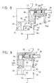
- Figs. 7 to 11 show a second embodiment of the invention.
- a housing 52 of a female connector 51 for receiving female metal terminals 30 has an L-shaped cross-section as shown in Fig. 8, and terminal receiving chambers 39 of an L-shape are formed in this housing 52 as in the first embodiment.
- a male connector 53 that connects with the female connector 51 has a guide plate 55 disposed between two projected tab portions 20 and perpendicular to the abutment wall 14.
- the guide plate 55 includes a main portion of a predetermined width extending upright from a bottom surface 54 of the male connector 53 to a level or height generally equal to that of the tab portions 20, and an extension projecting outwardly from an upper portion of this main portion.
- the bottom surface 54 of the male connector 53 projects outwardly in beneath the extension of the guide plate 55.
- the housing 52 of the female connector 51 has a fitting groove 57 for receiving the guide plate 55, the fitting groove 57 being disposed centrally along the width of the housing 52.
- the fitting groove 57 extends through a vertical portion 52a (which receives connection portions 31 of female metal terminals 30) of the housing 52 from a front surface thereof to a rear surface thereof in a direction along a length of a bottom surface of a horizontal portion 52b of the housing 52.
- a pair of limitation portions 59 are formed respectively on opposite sides of the extension of the guide plate 55, and an upper surface of each of the limitation portions 59 serves as a sliding surface 60 for establishing sliding contact with an end surface 45a (in which terminal insertion ports 45 are formed) of the female connector 51 when the female connector 51 is pushed parallel to the bottom surface 54 of the male connector 53.
- the dimension between the sliding surface 60 of each limitation portion 59 and the lower surface 11a of the mounting leg 11 is generally equal to the height of the female connector 51.
- the length of the sliding surfaces 60 is greater than that of the sliding surfaces 23 in the first embodiment so that the female connector 51 can slide over the sliding surfaces 60 immediately before the front surface of the female connector 51 is brought into abutment against the abutment wall 14.
- An elastically-deformable support member 62 is formed integrally with and depends from a lower surface of a distal end portion of the horizontal portion 52b of the housing 52.
- the support member 62 is disposed centrally along the width of the horizontal portion 52b.
- a pair of hook-like lock portions 63 are formed on opposite sides of the support member 62, respectively.
- a pair of hook-like lock piece portions 65 that lock with the respective lock portions 63 are formed on a projected portion 64 projecting from the bottom surface 54 of the male connector 53.
- the female connector 51 is brought into abutment against the abutment wall 14, and then is pushed into abutment against the bottom surface 54 of the male connector 53 along the abutment wall 14 such that the lock portions 63 are engaged with the lock piece portions 65, respectively.
- the lock portion 63 and the lock piece portion 65 have tapering surfaces 63a and 65a, respectively.
- a push portion 67 is formed at the lower end of the support member 62, and the support member 62 is forcibly flexed through this push portion 67 so as to release the locking engagement.
- each male metal terminal 19 is inserted into the terminal insertion port 45 through an insertion groove 46 from the front side.
- the tab portion 20 is inserted into the central portion of the terminal insertion port 45, and is disposed just beneath the connection portion 31 of the female metal terminal 30, as shown in Fig. 9.
- the two limitation portions 59 formed on the guide plate 55 are disposed outwardly of the vertical portion 52a of the female connector 51, and the lock portions 63 on the female connector 51 are disposed just above the lock piece portions 65, respectively.
- the female connector 51 is then pushed toward the bottom surface 54 of the male connector 53 in a direction of arrow D (Fig. 9), with the guide plate 55 inserted deep into the fitting groove 57. At this time, the female connector 51 is pushed with its front surface held in sliding contact with the abutment wall 14. As a result, the female connector 51 can be pushed straight toward the bottom surface 54 of the male connector 53 without shaking. As the female connector 51 is pushed, the tab portions 20 are gradually fitted into the connection portions 31 of the female metal terminals 30, respectively, and the tapering surface 63a of each lock portion 63 contacts the tapering surface 65a of the associated lock piece portion 65, so that the downwardly-moving support member 62 is elastically deformed.
- each tab portion 20 is fitted deep within the connection portion 31 of the associated female metal terminal 30.
- the push portion 67 of the support member 62 is pushed in a direction of arrow E (Fig. 11) to forcibly flex the support member 62 inwardly to disengage the respective lock portions 63 from the lock piece portions 65.
- the female connector 51 is then guided upwardly along the abutment wall 14 and pulled forward.
- the female connector 51 can be fitted relative to the male connector through the L-shaped path. Therefore, even if insufficient space exists in front of the tab portions 20, the female connector 51 can be fitted from the position in front of the tab portions 20. Further, each tab portion 20 and the connection portion 31 of the associated female metal terminal 30 can be contacted with each other along the length thereof, thus providing the sufficient area of contact between the two to achieve a reliable electrical connection.
- the lock mechanism is provided for locking the female connector 51 in its fitted condition, and therefore even if a pulling force acts on a wire 35, the female connector 51 will not be disengaged from the male connector 53.
- the female connector 25 can be pushed without shaking.
- the female connector 25 can be pushed without shaking.
- the lower surface 11a of the mounting leg 11 and the abutment wall 14 perform the function of the limitation portions 22. Therefore, the limitation portions 22 can be omitted.
- the female connector instead of the male connector can be connected to the motor.
- the present invention can be applied not only to the connector device for direct connection to the motor but also to electrical connection constructions of the general type employing female and male connectors in which the fitting space is limited.
Landscapes
- Details Of Connecting Devices For Male And Female Coupling (AREA)
- Motor Or Generator Frames (AREA)
Claims (18)
- Structure de connexion électrique comprenant :un connecteur mâle (15, 53) présentant un boítier de connecteur mâle (2) avec une face à bornes de connexion mâles traversée par des bornes mâles (19);un connecteur femelle (25, 51) présentant un boítier de connecteur femelle (26, 52) avec des bornes femelles (30) disposées de façon à se connecter avec les bornes mâles (19) à travers une face à bornes de connexion femelles du boítier de connecteur femelle;une portion de guidage (21 - 24, 55, 59, 60) qui guide l'un ou l'autre du connecteur mâle (15, 53) et du connecteur femelle (25, 51) dans une direction de guidage entrecoupant un axe normal s'étendant à la perpendiculaire de la face à bornes de connexion de l'autre du boítier de connecteur mâle ou du boítier de connecteur femelle; etune portion de positionnement (14) qui arrête en position d'alignement celui qui, du connecteur mâle (15, 53) ou du connecteur femelle (25, 51), est guidé, dès qu'un contact est établi avec la portion de positionnement (14), de façon telle que les bornes mâles (19) du connecteur mâle soient alignées sur les bornes femelles (30) du connecteur femelle, structure dans laquelle :la portion de guidage comprend une plaque de guidage (21, 55) fixée à l'autre, du connecteur mâle (15, 53) ou du connecteur femelle (25, 51), et une rainure (41, 57) à plaque de guidage façonnée de façon à recevoir la plaque de guidage et formée dans celui qui, du connecteur mâle ou du connecteur femelle, est guidé; et dans laquellela portion de guidage (21 - 24, 55, 59, 60) comprend une portion de limitation (22, 59) et celui qui, du connecteur mâle (15, 53) ou du connecteur femelle (25, 51) est guidé, comprend une rainure de guidage (49) façonnée de manière à recevoir la portion de limitation en position d'alignement, de façon telle que la portion de limitation s'emboíte dans la rainure de guidage lorsque le connecteur mâle et le connecteur femelle sont poussés l'un vers l'autre.
- Structure de connexion électrique selon la revendication 1, dans laquelle celui qui, du connecteur mâle (15,53) ou du connecteur femelle (25, 51), est guidé, est agencé de façon telle par rapport à l'autre du connecteur mâle ou du connecteur femelle, que la direction du guidage soit sensiblement perpendiculaire à l'axe normal en partant de la face à bornes de l'autre connecteur, mâle ou femelle.
- Structure de connexion électrique selon la revendication 1 ou 2, dans laquelle la portion de positionnement comprend un élément de positionnement (14) façonné de façon à venir en contact avec le boítier de celui qui, du connecteur mâle ou de connecteur femelle, est guidé, de manière à arrêter celui qui, du connecteur mâle ou du connecteur femelle, est guidé.
- Structure de connexion électrique selon l'une des revendications qui précèdent, dans laquelle celui qui, du connecteur mâle (15, 53) ou du connecteur femelle (25, 51), est guidé, est en contact coulissant avec au moins l'élément de positionnement (14).
- Structure de connexion électrique selon l'une des revendications qui précèdent, dans laquelle la rainure de guidage (49) est à peu près perpendiculaire à la direction de guidage, de sorte qu'un emboítement entre la rainure de guidage et la portion de limitation (22, 59) empêche celui qui, du connecteur mâle ou du connecteur femelle, est guidé, de bouger dans la direction du guidage.
- Structure de connexion électrique selon l'une des revendications qui précèdent, comprenant encore un mécanisme de verrouillage (63, 65) qui immobilise le connecteur mâle et le connecteur femelle, l'un par rapport à l'autre, lorsque le connecteur mâle et le connecteur femelle placés en position d'alignement sont poussés l'un vers l'autre.
- Structure de connexion électrique selon la revendication 6, dans laquelle le mécanisme de verrouillage comprend des éléments de verrouillage (65) fixés au connecteur mâle et des éléments de verrouillage correspondants (63) fixés au connecteur femelle, et dans laquelle les éléments de verrouillage sont agencés de façon à s'emboíter avec les éléments de verrouillage correspondants lorsque le connecteur mâle et le connecteur femelle placés en position d'alignement sont sollicités l'un vers l'autre.
- Structure de connexion électrique selon l'une des revendications qui précèdent, dans laquelle la plaque de guidage (21, 55) dépasse d'une première hauteur, partant de la face à bornes entre les bornes de l'un ou l'autre du connecteur mâle ou du connecteur femelle.
- Structure de connexion électrique selon l'une des revendications qui précèdent, dans laquelle la rainure (41, 57) pour plaque de guidage s'étend dans la direction de guidage.
- Structure de connexion électrique selon la revendication 8 ou 9, dans laquelle la plaque de guidage (21, 55) comprend des surfaces de guidage (23, 60) agencées sur au moins une face de la plaque de guidage, à une seconde hauteur inférieure à la première, les surfaces de guidage supportant, avec une possibilité de coulissement, celui, du connecteur mâle ou du connecteur femelle, qui est guidé.
- Structure de connexion électrique selon la revendication 10, dans laquelle les surfaces de guidage (23, 60) comprennent les portions de limitation (22, 59) qui s'avancent vers l'extérieur en partant de la plaque de guidage (21, 55), dans une direction à peu près perpendiculaire à la direction du guidage.
- Structure de connexion électrique selon l'une des revendications qui précèdent, dans laquelle la portion de positionnement est une paroi de butée (14) qui vient en contact avec celui qui, du connecteur mâle ou du connecteur femelle, est guidé, la paroi de butée étant agencée à peu près parallèlement aux bornes (19, 30) de l'autre, du connecteur mâle ou du connecteur femelle, et perpendiculairement à la face à bornes de connexion de ce dernier.
- Structure de connexion électrique selon l'une des revendications qui précèdent, dans laquelle les bornes (30) du connecteur femelle sont en forme de L et comprennent des portions d'extrémité (31) de bornes femelles qui sont à peu près perpendiculaires à des portions de connexion (35) de câbles à bornes femelles.
- Procédé d'assemblage de la structure de connexion électrique selon l'une des revendications qui précèdent, de façon à ce que des bornes respectives (19, 30) des premier et second connecteurs établissent un contact électrique, le procédé comprenant les opérations consistant à :guider l'un ou l'autre du connecteur mâle (15, 53) ou du connecteur femelle (25, 51) avec la portion de guidage dans la direction de guidage qui entrecoupe l'axe normal qui est parallèle aux bornes de l'autre, du connecteur mâle ou connecteur femelle, vers la portion de positionnement (14), l'opération de guidage comprenant l'opération consistant à placer et guider la plaque de guidage (21, 55) dans la rainure (41, 57) à plaque de guidage;arrêter celui qui, du connecteur mâle ou du connecteur femelle, est guidé, par contact avec la portion de positionnement (14), de façon à ce que les bornes du connecteur mâle soient alignées sur les bornes du connecteur femelle;placer la portion de limitation (22, 59) dans la rainure de guidage (49); etla portion de limitation étant emboítée avec la rainure de guidage, pousser le connecteur mâle (15, 53) et le connecteur femelle (25, 51) ensemble dans une direction transversale à la direction du guidage, en position d'emboítement, de sorte que les bornes respectives (19, 30) se contactent entre elles.
- Procédé selon la revendication 14, dans lequel l'opération de poussée consiste à verrouiller connecteur mâle et le connecteur femelle en position d'emboítement.
- Procédé selon la revendication 14 ou 15, dans lequel l'opération d'arrêt consiste à mettre un boítier (2, 26, 52) de celui qui, du connecteur mâle ou du connecteur femelle, est guidé, en contact avec la portion de positionnement (14).
- Procédé selon la revendication 14, 15 ou 16, dans lequel l'opération de guidage consiste à guider l'un ou l'autre du connecteur mâle ou du connecteur femelle dans la direction de guidage, à peu près perpendiculairement à l'axe normal.
- Procédé selon l'une des revendications 14 à 17, dans lequel l'opération d'arrêt consiste à aligner la portion de limitation (22, 59) sur la rainure de guidage (49).
Applications Claiming Priority (3)
| Application Number | Priority Date | Filing Date | Title |
|---|---|---|---|
| JP331120/94 | 1994-12-07 | ||
| JP6331120A JPH08163812A (ja) | 1994-12-07 | 1994-12-07 | 電気接続構造 |
| JP33112094 | 1994-12-07 |
Publications (3)
| Publication Number | Publication Date |
|---|---|
| EP0716478A2 EP0716478A2 (fr) | 1996-06-12 |
| EP0716478A3 EP0716478A3 (fr) | 1997-04-23 |
| EP0716478B1 true EP0716478B1 (fr) | 2000-07-26 |
Family
ID=18240096
Family Applications (1)
| Application Number | Title | Priority Date | Filing Date |
|---|---|---|---|
| EP95119241A Expired - Lifetime EP0716478B1 (fr) | 1994-12-07 | 1995-12-06 | Structure et procédé de connexion électrique |
Country Status (4)
| Country | Link |
|---|---|
| US (1) | US5816839A (fr) |
| EP (1) | EP0716478B1 (fr) |
| JP (1) | JPH08163812A (fr) |
| DE (1) | DE69518135T2 (fr) |
Cited By (1)
| Publication number | Priority date | Publication date | Assignee | Title |
|---|---|---|---|---|
| CN105264716A (zh) * | 2013-05-30 | 2016-01-20 | 矢崎总业株式会社 | 连接器 |
Families Citing this family (18)
| Publication number | Priority date | Publication date | Assignee | Title |
|---|---|---|---|---|
| US5904327A (en) * | 1997-12-30 | 1999-05-18 | Behavior Tech Computer Corp. | Detachable wrist support of keyboard |
| JP3531788B2 (ja) * | 1998-04-28 | 2004-05-31 | 矢崎総業株式会社 | コネクタの接続構造 |
| IT1317303B1 (it) * | 2000-01-05 | 2003-06-16 | Inarca Spa | Gruppo di connessione particolarmente per gli avvolgimenti di unostatore di motore elettrico. |
| FR2805675B1 (fr) * | 2000-02-25 | 2002-07-12 | Ecia Equip Composants Ind Auto | Moteur electrique, notamment pour groupe moto-ventilateur de vehicule automobile |
| JP3614380B2 (ja) * | 2001-05-17 | 2005-01-26 | 三菱電機株式会社 | 電動式パワーステアリング装置 |
| US6903473B2 (en) * | 2002-09-17 | 2005-06-07 | Asmo Co. Ltd. | Motor having connector housing |
| DE10301003B3 (de) | 2003-01-13 | 2004-09-30 | Siemens Ag | Modulares Installationsgerät |
| JP4473042B2 (ja) | 2004-05-26 | 2010-06-02 | 株式会社ジェイテクト | トルク検出装置、ワイヤーハーネス、電動パワーステアリング装置及び端子ホルダ |
| JP4722707B2 (ja) | 2005-10-13 | 2011-07-13 | 日本圧着端子製造株式会社 | 垂直嵌合雌端子及びこれが装着されるハウジング |
| US20080076305A1 (en) * | 2006-09-25 | 2008-03-27 | Alltop Technology Co., Ltd. | Connector base structures for a connector |
| DE102007061117A1 (de) * | 2007-12-19 | 2009-06-25 | Robert Bosch Gmbh | Elektrische Kontaktierung |
| JP2009181769A (ja) * | 2008-01-30 | 2009-08-13 | Kyocera Elco Corp | コネクタ、プラグコネクタ、及び携帯端末 |
| JP4792517B2 (ja) * | 2009-07-07 | 2011-10-12 | 日本航空電子工業株式会社 | コネクタ組立体 |
| JP4719305B1 (ja) * | 2010-08-27 | 2011-07-06 | イリソ電子工業株式会社 | コネクタ |
| JP5673309B2 (ja) * | 2011-04-05 | 2015-02-18 | 住友電装株式会社 | 車両側コネクタ |
| CN103618171B (zh) * | 2013-11-29 | 2015-09-02 | 浩亭(珠海)制造有限公司 | 公连接器、母连接器和连接器组件 |
| JP6513542B2 (ja) * | 2015-09-29 | 2019-05-15 | 日本航空電子工業株式会社 | コネクタ及びコネクタ組立体 |
| JP2019030142A (ja) * | 2017-07-31 | 2019-02-21 | 日本電産テクノモータ株式会社 | コネクタ及びコネクタを備えたモータ |
Family Cites Families (9)
| Publication number | Priority date | Publication date | Assignee | Title |
|---|---|---|---|---|
| US4445740A (en) * | 1982-04-26 | 1984-05-01 | Rockwell International Corporation | Circuit board assembly |
| US4698025A (en) * | 1986-09-15 | 1987-10-06 | Molex Incorporated | Low profile modular phone jack assembly |
| JPH0480259A (ja) * | 1990-07-20 | 1992-03-13 | Ube Ind Ltd | 延伸ポリアミドフィルム用樹脂組成物 |
| JPH0480258A (ja) * | 1990-07-23 | 1992-03-13 | Mitsubishi Petrochem Co Ltd | 熱可塑性樹脂組成物 |
| FR2671439B1 (fr) * | 1990-11-21 | 1994-10-21 | Jidosha Denki Kogyo Kk | Petit moteur electrique comportant un connecteur d'alimentation en energie. |
| JP2525364Y2 (ja) | 1990-11-21 | 1997-02-12 | 自動車電機工業株式会社 | 小型モータ |
| US5167520A (en) * | 1991-10-18 | 1992-12-01 | Amp Incorporated | Cup fit plug connector |
| GB9225118D0 (en) * | 1992-12-01 | 1993-01-20 | Amp Gmbh | Shunted airbag connector |
| JPH08163813A (ja) * | 1994-12-07 | 1996-06-21 | Sumitomo Wiring Syst Ltd | コネクタ |
-
1994
- 1994-12-07 JP JP6331120A patent/JPH08163812A/ja active Pending
-
1995
- 1995-11-30 US US08/565,578 patent/US5816839A/en not_active Expired - Fee Related
- 1995-12-06 EP EP95119241A patent/EP0716478B1/fr not_active Expired - Lifetime
- 1995-12-06 DE DE69518135T patent/DE69518135T2/de not_active Expired - Fee Related
Cited By (2)
| Publication number | Priority date | Publication date | Assignee | Title |
|---|---|---|---|---|
| CN105264716A (zh) * | 2013-05-30 | 2016-01-20 | 矢崎总业株式会社 | 连接器 |
| CN105264716B (zh) * | 2013-05-30 | 2017-04-12 | 矢崎总业株式会社 | 连接器 |
Also Published As
| Publication number | Publication date |
|---|---|
| EP0716478A3 (fr) | 1997-04-23 |
| US5816839A (en) | 1998-10-06 |
| EP0716478A2 (fr) | 1996-06-12 |
| JPH08163812A (ja) | 1996-06-21 |
| DE69518135T2 (de) | 2001-03-22 |
| DE69518135D1 (de) | 2000-08-31 |
Similar Documents
| Publication | Publication Date | Title |
|---|---|---|
| EP0716478B1 (fr) | Structure et procédé de connexion électrique | |
| US5605472A (en) | Connector fitting detection mechanism | |
| JP2590878Y2 (ja) | コネクタカバー構造 | |
| US6244880B1 (en) | Low-insertion force connector | |
| US6840789B2 (en) | Connector and a method of assembling it | |
| EP0622867B1 (fr) | Connecteur | |
| EP0374455B1 (fr) | Construction pour la rétention d'une pièce de connexion | |
| US5924880A (en) | Low coupling force connector assembly | |
| US5190467A (en) | Connector | |
| US5246380A (en) | Connector | |
| JP3301329B2 (ja) | コネクタ | |
| US5169327A (en) | Connector including cam member operable for performing a fitting operation | |
| JPH08273760A (ja) | ロック式電気コネクタ | |
| JP2946000B2 (ja) | 電気コネクタ | |
| US5088938A (en) | Terminal locking block for electrical connectors | |
| JP2001230021A (ja) | コネクタ | |
| EP0716479B1 (fr) | Assemblage de connecteur avec des éléments de contact coopérants et son procédé de connexion | |
| US5571032A (en) | Coupled housing type connector | |
| US6250945B1 (en) | Half-fitting prevention connector | |
| JPH09245869A (ja) | 端子係止具付きコネクタ | |
| US5647752A (en) | Lever-type connector | |
| JP3294193B2 (ja) | シールドコネクタ | |
| JP3687537B2 (ja) | 分割コネクタ | |
| US6027378A (en) | Combined-type connector | |
| US6325663B1 (en) | Half-fitting prevention connector |
Legal Events
| Date | Code | Title | Description |
|---|---|---|---|
| PUAI | Public reference made under article 153(3) epc to a published international application that has entered the european phase |
Free format text: ORIGINAL CODE: 0009012 |
|
| AK | Designated contracting states |
Kind code of ref document: A2 Designated state(s): DE GB |
|
| PUAL | Search report despatched |
Free format text: ORIGINAL CODE: 0009013 |
|
| AK | Designated contracting states |
Kind code of ref document: A3 Designated state(s): DE GB |
|
| 17P | Request for examination filed |
Effective date: 19970603 |
|
| 17Q | First examination report despatched |
Effective date: 19990330 |
|
| GRAG | Despatch of communication of intention to grant |
Free format text: ORIGINAL CODE: EPIDOS AGRA |
|
| GRAG | Despatch of communication of intention to grant |
Free format text: ORIGINAL CODE: EPIDOS AGRA |
|
| GRAH | Despatch of communication of intention to grant a patent |
Free format text: ORIGINAL CODE: EPIDOS IGRA |
|
| RIC1 | Information provided on ipc code assigned before grant |
Free format text: 7H 01R 24/00 A, 7H 01R 13/629 B |
|
| GRAH | Despatch of communication of intention to grant a patent |
Free format text: ORIGINAL CODE: EPIDOS IGRA |
|
| GRAA | (expected) grant |
Free format text: ORIGINAL CODE: 0009210 |
|
| AK | Designated contracting states |
Kind code of ref document: B1 Designated state(s): DE GB |
|
| REF | Corresponds to: |
Ref document number: 69518135 Country of ref document: DE Date of ref document: 20000831 |
|
| EN | Fr: translation not filed | ||
| PLBE | No opposition filed within time limit |
Free format text: ORIGINAL CODE: 0009261 |
|
| STAA | Information on the status of an ep patent application or granted ep patent |
Free format text: STATUS: NO OPPOSITION FILED WITHIN TIME LIMIT |
|
| 26N | No opposition filed | ||
| PGFP | Annual fee paid to national office [announced via postgrant information from national office to epo] |
Ref country code: GB Payment date: 20011205 Year of fee payment: 7 |
|
| REG | Reference to a national code |
Ref country code: GB Ref legal event code: IF02 |
|
| PGFP | Annual fee paid to national office [announced via postgrant information from national office to epo] |
Ref country code: DE Payment date: 20020109 Year of fee payment: 7 |
|
| PG25 | Lapsed in a contracting state [announced via postgrant information from national office to epo] |
Ref country code: GB Free format text: LAPSE BECAUSE OF NON-PAYMENT OF DUE FEES Effective date: 20021206 |
|
| PG25 | Lapsed in a contracting state [announced via postgrant information from national office to epo] |
Ref country code: DE Free format text: LAPSE BECAUSE OF NON-PAYMENT OF DUE FEES Effective date: 20030701 |
|
| GBPC | Gb: european patent ceased through non-payment of renewal fee |