EP1237120A2 - Drucker und Drucksystem - Google Patents
Drucker und Drucksystem Download PDFInfo
- Publication number
- EP1237120A2 EP1237120A2 EP02004199A EP02004199A EP1237120A2 EP 1237120 A2 EP1237120 A2 EP 1237120A2 EP 02004199 A EP02004199 A EP 02004199A EP 02004199 A EP02004199 A EP 02004199A EP 1237120 A2 EP1237120 A2 EP 1237120A2
- Authority
- EP
- European Patent Office
- Prior art keywords
- printhead
- information
- printing
- characteristic information
- host
- Prior art date
- Legal status (The legal status is an assumption and is not a legal conclusion. Google has not performed a legal analysis and makes no representation as to the accuracy of the status listed.)
- Granted
Links
Images


Classifications
-
- G—PHYSICS
- G06—COMPUTING OR CALCULATING; COUNTING
- G06F—ELECTRIC DIGITAL DATA PROCESSING
- G06F3/00—Input arrangements for transferring data to be processed into a form capable of being handled by the computer; Output arrangements for transferring data from processing unit to output unit, e.g. interface arrangements
- G06F3/12—Digital output to print unit, e.g. line printer, chain printer
-
- G—PHYSICS
- G06—COMPUTING OR CALCULATING; COUNTING
- G06K—GRAPHICAL DATA READING; PRESENTATION OF DATA; RECORD CARRIERS; HANDLING RECORD CARRIERS
- G06K15/00—Arrangements for producing a permanent visual presentation of the output data, e.g. computer output printers
- G06K15/02—Arrangements for producing a permanent visual presentation of the output data, e.g. computer output printers using printers
- G06K15/18—Conditioning data for presenting it to the physical printing elements
- G06K15/1801—Input data handling means
- G06K15/1803—Receiving particular commands
- G06K15/1805—Receiving printer configuration commands
Definitions
- This invention relates to a printing apparatus and printing system and, more particularly, to a printing apparatus which comprises an inkjet printhead, and a printing system using that printing apparatus.
- a printer apparatus which comprises a non-volatile memory such as an EEPROM, flash memory, or the like, that stores individual information such as the operation state, operation history, production number, device ID, and the like of a printhead used in that printer apparatus, and control information such as print position correction information of a head carriage upon reciprocal printing and the like, is known.
- a non-volatile memory such as an EEPROM, flash memory, or the like
- Japanese Patent Publication Laid-Open No. 5-309839 discloses a printer apparatus which stores information used to correct a mount error of a printhead
- Japanese Patent Publication Laid-Open No. 8-224890 discloses a printer apparatus which stores time information elapsed after the previous recovery operation of a printhead
- Japanese Patent Publication Laid-Open No. 2000-35922 discloses a printer apparatus which stores control information of an ink residual amount, head cleaning time, the position of a printhead, a roll paper residual amount, and the like.
- Japanese Patent Publication Laid-Open No. 10-278360 discloses a printer apparatus in which a printhead unit comprises an EEPROM, and stores information such as the operation characteristics and the like of that printhead.
- all of control information, characteristic information of the printhead, and the like can be stored in a single non-volatile memory together as in the above prior art.
- the physical mount position of the non-volatile memory can be either on the printer main body side or printhead side, as long as they can exchange information.
- both the printer apparatus and printhead comprise non-volatile memories such as EEPROMs or the like to respectively hold necessary information.
- a printing apparatus main body comprises a non-volatile memory, which has been conventionally provided to both the printing apparatus main body and printhead, so as to unifiedly manage control information, characteristic information of a printhead, and the like.
- a printing apparatus for printing on a printing medium using a printhead, comprising: an interface which is connected to a host and receives information from the host; a non-volatile memory for storing characteristic information of the printhead; discriminating means for discriminating whether or not a command sent from the host is a command including the characteristic information of the printhead; write control means for controlling to write the characteristic information of the printhead into the non-volatile memory in accordance with a discrimination result of the discriminating means; and printing control means for controlling the printhead to print in accordance with the characteristic information written into the non-volatile memory.
- the characteristic information preferably includes type information of the printhead, and the write control means controls to write the characteristic information of the printhead for each type of printhead.
- the printhead is detachable from a printing apparatus main body, and a user can selectively attach a desired one of a plurality of types of printheads to the printing apparatus.
- the discriminating means preferably includes means for receiving a command outputted from the host to which the characteristic information of the printhead indicated on the printhead or an accessory of the printhead in a format identifiable to human or an electronic device is inputted by man-machine interactive operation or the electronic device.
- the printhead is an inkjet printhead for printing by discharging ink
- the inkjet printhead preferably comprises an electrothermal transducer for generating heat energy to be given to ink so as to discharge ink by utilizing the heat energy.
- the non-volatile memory includes an EEPROM.
- the foregoing object is attained by providing a printing system including the above-described printing apparatus, and a host connecting to the printing apparatus and capable of communicating with a second system via a network, the host comprising: input means for inputting individual information of a printhead indicated on the printhead or an accessory of the printhead in a format identifiable to human or an electronic device via man-machine interactive operation or the electronic device; retrieve means for accessing to the second system via the network on the basis of the individual information of the printhead inputted by the input means, and retrieving characteristic information of the printhead corresponding to the individual information of the printhead; and transfer means for transferring the characteristic information of the printhead retrieved by the retrieve means to the printing apparatus.
- the network includes a LAN or Internet, and the individual information of the print head can be a production number of the printhead.
- the second system has a database in which information is retrievable via the network, and the database holds characteristic information of the printhead corresponding to the individual information of the printhead.
- the format identifiable to human is at least one of a digit and a character string
- the format identifiable to the electronic device is a barcode
- the characteristic information of the printhead is input by the man-machine interactive operation
- at least one of a digit and a character string is preferably input to the host.
- a barcode is preferably read by a barcode reader.
- the characteristic information of a printhead indicated on the printhead or its accessory in a format identifiable to human or an electronic device is input to a host by man-machine interactive operation or electronically by the electronic device.
- the printing apparatus discriminates whether or not a command sent from the host via an interface contains the characteristic information of the printhead, controls to write the characteristic information of the printhead in a non-volatile memory in accordance with the discriminating result, and controls the printhead to print.
- the invention is particularly advantageous since a non-volatile memory for storing characteristic information is no longer required for a printhead unlike in the conventional apparatus.
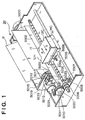
- Fig. 1 is a perspective view showing the outer appearance of an ink-jet printer 20 (hereinafter referred to as a printer) as a typical embodiment of the present invention.
- a carriage HC engages with a spiral groove 5004 of a lead screw 5005, which rotates via driving force transmission gears 5009 to 5011 upon forward/reverse rotation of a driving motor 5013.
- the carriage HC has a pin (not shown), and is reciprocally scanned in the directions of arrows a and b in Fig. 1.
- An integrated ink-jet cartridge IJC which incorporates a printhead IJH and an ink tank IT is mounted on the carriage HC.
- Reference numeral 5002 denotes a sheet pressing plate, which presses a paper sheet against a platen 5000, ranging from one end to the other end of the scanning path of the carriage.
- Reference numerals 5007 and 5008 denote photocouplers which serve as a home position detector for recognizing the presence of a lever 5006 of the carriage in a corresponding region, and used for switching, e.g., the rotating direction of the motor 5013.
- Reference numeral 5016 denotes a member for supporting a cap member 5022, which caps the front surface of the printing head IJH; and 5015, a suction device for sucking ink residue through the interior of the cap member.
- the suction device 5015 performs suction recovery of the printing head via an opening 5023 of the cap member 5015.
- Reference numeral 5017 denotes a cleaning blade; 5019, a member which allows the blade to be movable in the back-and-forth direction of the blade. These members are supported on a main unit support plate 5018. The shape of the blade is not limited to this, but a known cleaning blade can be used in this embodiment.
- Reference numeral 5021 denotes a lever for initiating a suction operation in the suction recovery operation. The lever 5021 moves upon movement of a cam 5020, which engages with the carriage, and receives a driving force from the driving motor via a known transmission mechanism such as clutch switching.
- the capping, cleaning, and suction recovery operations are performed at their corresponding positions upon operation of the lead screw 5005 when the carriage reaches the home-position side region.
- the present invention is not limited to this arrangement as long as desired operations are performed at known timings.
- Fig. 2 is a block diagram showing the arrangement of a control circuit of the printer 20.
- reference numeral 1700 denotes an USB interface for inputting a printing signal from a personal computer 21 (hereinafter referred to as a host); 1701, an MPU; 1702, a programmable ROM for storing a control program executed by the MPU 1701 and necessary control data; and 1703, a DRAM for storing various data (the printing signal, printing data supplied to the printhead IJH, and the like).
- Reference numeral 1704 denotes a gate array (G.A.) for performing supply control of printing data to the printhead IJH.
- G.A. gate array
- the gate array 1704 also performs data transfer control among the interface 1700, the MPU 1701, and the RAM 1703.
- Reference numeral 1710 denotes a carrier motor for carrying the printhead IJH; and 1709, a conveyance motor for conveying a printing medium (e.g. a printing sheet).
- Reference numeral 1705 denotes a head driver for driving the printhead IJH; and 1706 and 1707, motor drivers for driving the conveyance motor 1709 and the carrier motor 1710.
- Reference numeral 1708 denotes an EEPROM used to store the characteristic information of a printhead in addition to the production number, operation state, various kinds of correction information, and the like of the printer.
- print data is input to the interface 1700, it is converted into a print signal between the gate array 1704 and MPU 1701.
- the motor drivers 1706 and 1707 are driven, and the printhead IJH is driven in accordance with print data sent to the head driver 1705, thus printing.
- an ink tank IT and the printhead IJH may be integrally formed to constitute an exchangeable ink cartridge IJC, as described above. Also, the ink tank IT and the printhead IJH may be separably arranged, and the ink tank IT alone may be exchanged when ink is exhausted.
- USB interface 1700 interfaces of other standards, e.g., a Centronics or IEEE1284 interface may be used.
- Fig. 3 is a perspective view showing the structure of an ink cartridge IJC in which an ink tank and printhead are separable.
- an ink tank IT and printhead IJH are separable at the position of a boundary line K.
- the ink cartridge IJC has electrodes (not shown) for receiving an electrical signal supplied from the carriage HC when it is mounted on a carriage HC. This electrical signal drives printing elements of the printhead IJH to discharge ink, as described above.
- reference numeral 500 in Fig. 3 denotes an ink discharge port array.
- the ink tank IT has a fibrous or porous ink absorber for holding ink, and the ink absorber holds ink.
- a plurality of types of printheads are available: for example, a monochrome printhead, color printhead, photo-quality printhead, and the like.
- a user can selectively attach an optimal one of these printheads according to the user's need.
- Each of these printheads has a signal terminal which can output a 2-bit signal regardless of their types.
- the signal terminal for outputting a 2-bit signal used to identify the printhead type may be a dedicated terminal, but it may be commonly used as another signal terminal since that identification process is not always executed during the print process.
- the printer 20 of this embodiment receives print data from the host 21 via the USB interface 1700, generates a signal to be transferred to the printhead IJH based on the received information, and transfers the generated signal to the printhead IJH to control it to discharge ink onto a printing medium (e.g., a printing sheet), thus attaining a desired print process.
- a printing medium e.g., a printing sheet
- the host 21 and printer 20 exchange various commands and corresponding status values via the USB interface 1700, in addition to print data.
- These command status values include a write instruction of the characteristic information of the printhead IJH into the EEPROM 1708, in addition to confirmation of the operation state, confirmation of the presence/absence of errors, a head cleaning instruction, an ON/OFF instruction of the power supply of the printer 20, and the like.
- data sent from the host 21 is print data or a command
- the type of command if the data is a command can be identified based on a header appended to the header of that transferred data.
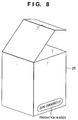
- Fig. 4 is a perspective view showing the outer appearance of a packaging paper box, which is an accompanying material with the printhead, for packing the printhead IJH.
- the characteristic information of the printhead or information related to the characteristic information which is converted into a hexadecimal character string code is indicated (printed) on the side surface of a packaging paper box 25 upon shipping.
- the information is appended with type information of a printhead and check sum information for error detection, and information of a total of 64 bits, which include: 52 bits for exact characteristic information such as the correction value of an ink discharge amount, the resistance of a heater for ink discharge, fluctuation correction value for each nozzle, and the like, or information related to the exact characteristic information; 4 bits for type information; and 8 bits for a check sum, is converted into an 8-digit, hexadecimal code.
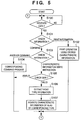
- step S100 the control waits for data received from the host 21. Upon detecting data reception, the flow advances to step S101 to check if the received data is print information or a command.
- step S102 If it is determined that the received data is print information, the flow advances to step S102, and the printhead is driven using the characteristic information corresponding to the type of currently mounted printhead on the basis of the characteristic information currently stored in the EEPROM 1708, thus making a print process. After that, the flow returns to step S100. On the other hand, if it is determined that the received data is a command, the flow advances to step S103.
- step S103 It is discriminated in step S103 if the command is a write instruction command of the characteristic information of a printhead into the EEPROM 1708 or another command. If it is discriminated that the received command is a command other than the write instruction of the characteristic information of a printhead, the flow advances to step S104 to execute a process corresponding to that received command. After that, the flow returns to step S100.
- step S105 If the received command is the write instruction of the characteristic information of a printhead into the EEPROM 1708, the flow advances to step S105 to confirm a check sum. If it is confirmed that the instruction is effective, the flow advances to step S106 to extract the type information of the printhead. Furthermore, the characteristic information of the printhead of that type, which is stored in the EEPROM 1708 is rewritten by the characteristic information received from the host 21 in step S107.
- this software need not be a standalone program, but may be activated as one of setup menus upon executing driver software.
- the characteristic information which is input in accordance with the instruction from the utility software which runs on the host 21 is set as an operand of a command that indicates a write instruction of the characteristic information of the printhead in the EEPROM 1708, and is sent to the printer 20 together with that command. In this way, the information is finally written into the EEPROM 1708.
- the characteristic information is written into the EEPROM 1708, a print process is performed using that characteristic information. Since the characteristic information of the printhead is written for each type of printhead, it need only be written once when the printhead is attached to the printer for the first time. Hence, the user need not write the characteristic information every time he or she exchanges the printhead by another type of printhead according to his or her purpose (e.g., the user exchanges a monochrome printhead by a color printhead).
- the characteristic information of a printhead is printed as a character code on the packaging paper box of that printhead, and the user reads and inputs that code via the keyboard.
- the host to which the printer is connected sends that code via the printer interface to write it into the EEPROM of the printer. In this manner, an EEPROM conventionally required in the printhead is no longer necessary.
- the EEPROM is used as a non-volatile memory.
- the present invention is not limited to such a specific memory.
- other non-volatile memories such as a flash memory and the like may be used.
- the characteristic information of the printhead is not only printed as a character code on the packaging paper box which is an accompanying material, but also directly printed, impressed or engraved on the side surface or the like of the printhead.
- the characteristic information may be printed or stamped on an accompanying material including a paper sheet such as a manual, warranty, or the like included in a package, or may be printed, impressed, or engraved on another accompanying material including an anti-dry packaging or wrapping material that wraps the printhead upon shipping.
- the present invention is applied to a case wherein a user writes the characteristic information of the printhead into the EEPROM of the printer. Also, the present invention can be applied to the production line of a factory.
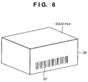
- Fig. 6 shows a packaging plastic box 26, which wraps a printhead, the top portion of which is covered by an openable film sealed by, e.g., heat welding or the like.
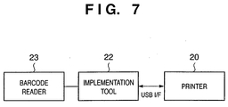
- FIG. 7 is a schematic block diagram showing an overview of a production line system of a factory that implements this embodiment.
- reference numeral 20 denotes a printer described in the above embodiment (no printhead is mounted since it is still on the production line in the factory); and 22, an implementation tool having the same USB interface as the USB interface 1700 of the printer 20.
- the implementation tool 22 is used to send the characteristic information of the printhead to the printer 20 as a command.
- a barcode reader 23 is connected to the implementation tool 22.
- the barcode seal 27 adhered on the side surface of the packaging plastic box 26 that stores a printhead is read using the barcode reader 23, and the read characteristic information is sent to the printer 20 using the implementation tool 22 and is written into the EEPROM 1708. After that, the printer 20 and packaging plastic box 26 can be shipped together in a single package.
- the characteristic information of the printhead is converted into a barcode to be indicated.
- the present invention is not limited to this.
- the characteristic information of the printhead may be printed in an electrically, magnetically or optically readable format such as magnetic recording, OCR, or the like other than the barcode.
- an implementation tool that comprises a corresponding reader is used.
- the characteristic information of a printhead to be packed can be efficiently read and written into the EEPROM of the corresponding printer.
- the characteristic information itself of the printhead is printed on the packaging paper box or packaging plastic box.
- the characteristic information itself need not always be printed.
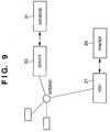
- a unique number such as the production number or the like of a printhead may be printed on the packaging paper box 25 of the printhead, and the characteristic information of the printhead may be retrieved from a database via a network on the basis of the unique number.
- the host 21 to which the printer 20 is connected is connected to the Internet, as shown in Fig. 9, the host 21 is set to be capable of accessing, via the Internet, a database 31 built in a server 30 provided by the manufacturer of the printer and printhead, and the database 31 accumulates characteristic information of all shipped printheads, so that characteristic information of a printhead can be retrieved based on the production number of the printhead. Then, the user can obtain the characteristic information corresponding to the production number of his or her printhead. In this way, the retrieved characteristic information of the printhead is sent from the host 21 to the printer 20, and is finally written into the EEPROM 1708.
- the characteristic information of the printhead is remotely acquired via the Internet. If the Internet is replaced by a LAN, and the host 21 is replaced by the implementation tool 22, this method can be used in the production line of the factory.
- the liquid discharged from the printhead has been described as ink
- the liquid contained in the ink tank has been described as ink.
- the liquid is not limited to ink.
- the ink tank may contain processed liquid or the like discharged to a print medium to improve fixability or water repellency of a printed image or to increase the image quality.
- a printer which comprises means (e.g., an electrothermal transducer, laser beam generator, and the like) for generating heat energy as energy utilized upon execution of ink discharge, and causes a change in state of an ink by the heat energy, among the ink-jet printers.
- means e.g., an electrothermal transducer, laser beam generator, and the like
- heat energy as energy utilized upon execution of ink discharge
- the system is effective because, by applying at least one driving signal, which corresponds to printing information and gives a rapid temperature rise exceeding nucleate boiling, to each of electrothermal transducers arranged in correspondence with a sheet or liquid channels holding a liquid (ink), heat energy is generated by the electrothermal transducer to effect film boiling on the heat acting surface of the printhead, and consequently, a bubble can be formed in the liquid (ink) in one-to-one correspondence with the driving signal.
- the driving signal is applied as a pulse signal, the growth and shrinkage of the bubble can be attained instantly and adequately to achieve discharge of the liquid (ink) with the particularly high response characteristics.
- signals disclosed in U.S. Patent Nos. 4,463,359 and 4,345,262 are suitable. Note that further excellent printing can be performed by using the conditions described in U.S. Patent No. 4,313,124 of the invention which relates to the temperature rise rate of the heat acting surface.
- the arrangement using U.S. Patent Nos. 4,558,333 and 4,459,600 which disclose the arrangement having a heat acting portion arranged in a flexed region is also included in the present invention.
- the present invention can be effectively applied to an arrangement based on Japanese Patent Laid-Open Publication No. 59-123670 which discloses the arrangement using a slot common to a plurality of electrothermal transducers as a discharge portion of the electrothermal transducers, or Japanese Patent Laid-Open No. 59-138461 Publication which discloses the arrangement having an opening for absorbing a pressure wave of heat energy in correspondence with a discharge portion.
- an exchangeable chip type printhead which can be electrically connected to the apparatus main body and can receive ink from the apparatus main body upon being mounted on the apparatus main body can be employed as well as a cartridge type printhead in which an ink tank is integrally arranged on the printhead itself as described in the above embodiments.
- recovery means for the printhead, preliminary auxiliary means and the like to the above-described construction of the printer of the present invention since the printing operation can be further stabilized.
- a printing mode of the printer not only a printing mode using only a primary color such as black or the like, but also at least one of a multi-color mode using a plurality of different colors or a full-color mode achieved by color mixing can be implemented in the printer either by using an integrated printhead or by combining a plurality of printheads.
- the ink is a liquid.
- the present invention may employ an ink which is solid at room temperature or less and softens or liquefies at room temperature, or an ink which liquefies upon application of a use printing signal, since it is a general practice to perform temperature control of the ink itself within a range from 30°C to 70°C in the ink-jet system, so that the ink viscosity can fall within a stable discharge range.
- an ink which is solid in a non-use state and liquefies upon heating may be used.
- an ink which liquefies upon application of heat energy according to a printing signal and is discharged in a liquid state, an ink which begins to solidify when it reaches a printing medium, or the like is applicable to the present invention.
- the above-mentioned film boiling method is most effective for the above-mentioned inks.
- the ink-jet printer of the present invention may be used in the form of a copying machine combined with a reader and the like, or a facsimile apparatus having a transmission/reception function in addition to an image output terminal of an information processing apparatus such as a computer.
- the present invention can be applied to a system constituted by a plurality of devices (e.g., a host computer, an interface, a reader and a printer) or to an apparatus comprising a single device (e.g., a copy machine or a facsimile apparatus).
- a system constituted by a plurality of devices (e.g., a host computer, an interface, a reader and a printer) or to an apparatus comprising a single device (e.g., a copy machine or a facsimile apparatus).
- the object of the present invention can be also achieved by providing a storage medium (or recording medium) storing software program code for performing the aforesaid processes to a system or an apparatus, reading the program code with a computer (e.g., CPU, MPU) of the system or apparatus from the storage medium, then executing the program.
- a computer e.g., CPU, MPU
- the program code read from the storage medium realizes the functions according to the embodiments
- the storage medium storing the program code constitutes the invention.
- the present invention includes a case where an OS (operating system) or the like working on the computer performs a part or entire processes in accordance with designations of the program code and realizes functions according to the above embodiments.
- the present invention also includes a case where, after the program code read from the storage medium is written in a function expansion card which is inserted into the computer or in a memory provided in a function expansion unit which is connected to the computer, CPU or the like contained in the function expansion card or unit performs a part or entire process in accordance with designations of the program code and realizes functions of the above embodiments.
- This invention provides a low-cost, economical printing apparatus and printing system.
- characteristic information of a printhead which is described, printed, adhered, or formed on a printhead or its accessory (e.g., a packaging paper box) in a format identifiable to human or an electronic device is man-machine-interactively inputted to a host or electronically inputted to the host by a barcode reader or the like.
- the printing apparatus discriminates whether or not a command sent from the host via an interface is a command that includes characteristic information of the printhead, and control is made to write the characteristic information of the print head into a non-volatile memory (EEPROM) in accordance with the discriminating result.
- EEPROM non-volatile memory
- the printhead is controlled in accordance with the characteristic information written into the non-volatile memory to execute a print process.
Landscapes
- Engineering & Computer Science (AREA)
- Theoretical Computer Science (AREA)
- General Engineering & Computer Science (AREA)
- Physics & Mathematics (AREA)
- General Physics & Mathematics (AREA)
- Human Computer Interaction (AREA)
- Accessory Devices And Overall Control Thereof (AREA)
- Ink Jet (AREA)
- Record Information Processing For Printing (AREA)
Applications Claiming Priority (2)
| Application Number | Priority Date | Filing Date | Title |
|---|---|---|---|
| JP2001055463 | 2001-02-28 | ||
| JP2001055463A JP2002254622A (ja) | 2001-02-28 | 2001-02-28 | 記録装置及び記録システム |
Publications (3)
| Publication Number | Publication Date |
|---|---|
| EP1237120A2 true EP1237120A2 (de) | 2002-09-04 |
| EP1237120A3 EP1237120A3 (de) | 2002-11-13 |
| EP1237120B1 EP1237120B1 (de) | 2007-08-15 |
Family
ID=18915648
Family Applications (1)
| Application Number | Title | Priority Date | Filing Date |
|---|---|---|---|
| EP02004199A Expired - Lifetime EP1237120B1 (de) | 2001-02-28 | 2002-02-26 | Drucker und Drucksystem |
Country Status (6)
| Country | Link |
|---|---|
| US (1) | US6789865B2 (de) |
| EP (1) | EP1237120B1 (de) |
| JP (1) | JP2002254622A (de) |
| KR (1) | KR100537129B1 (de) |
| CN (1) | CN1288541C (de) |
| DE (1) | DE60221731T2 (de) |
Families Citing this family (13)
| Publication number | Priority date | Publication date | Assignee | Title |
|---|---|---|---|---|
| US6000645A (en) * | 1999-01-27 | 1999-12-14 | Bfk Technologies, Inc. | Axial flow, bi-rotor concrete reclaimer |
| JP2004109662A (ja) * | 2002-09-19 | 2004-04-08 | Ricoh Co Ltd | 不正使用防止方法、画像形成装置及び画像形成システム |
| JP2005219302A (ja) * | 2004-02-04 | 2005-08-18 | Noritsu Koki Co Ltd | 写真プリント装置 |
| CN100374300C (zh) * | 2004-11-04 | 2008-03-12 | 凌阳科技股份有限公司 | 喷墨打印控制装置 |
| US8328316B2 (en) * | 2009-10-26 | 2012-12-11 | Canon Kabushiki Kaisha | Inkjet printhead, printing apparatus, and printing method |
| JP5891708B2 (ja) * | 2011-10-28 | 2016-03-23 | セイコーエプソン株式会社 | 印刷装置 |
| EP2833696B1 (de) * | 2012-03-29 | 2017-07-19 | NGK Insulators, Ltd. | Mit einer informationsanzeige ausgestattete elektroheizung und verfahren zur verwendung von informationen dafür |
| CN102673019A (zh) * | 2012-05-11 | 2012-09-19 | 雷博尔自动化系统(惠州)有限公司 | 用于糊盒机的图档输入控制系统及方法 |
| EP3063009A4 (de) | 2013-10-31 | 2018-03-21 | Hewlett-Packard Development Company, L.P. | Druckköpfe mit darauf geformten speichern |
| US9889659B2 (en) | 2014-07-29 | 2018-02-13 | Hewlett-Packard Development Company, L.P. | Printhead with a memristor |
| CN106626769B (zh) * | 2017-01-04 | 2018-07-13 | 北京舞马科技有限公司 | 一种喷墨制造可变的Chipless RFID系统及方法 |
| JP2023060464A (ja) * | 2021-10-18 | 2023-04-28 | セイコーエプソン株式会社 | 液体吐出システム |
| JP7804252B2 (ja) * | 2022-03-16 | 2026-01-22 | セイコーエプソン株式会社 | システム、サーバプログラム、及びクライアントプログラム |
Family Cites Families (24)
| Publication number | Priority date | Publication date | Assignee | Title |
|---|---|---|---|---|
| CA1127227A (en) | 1977-10-03 | 1982-07-06 | Ichiro Endo | Liquid jet recording process and apparatus therefor |
| US4330787A (en) | 1978-10-31 | 1982-05-18 | Canon Kabushiki Kaisha | Liquid jet recording device |
| US4345262A (en) | 1979-02-19 | 1982-08-17 | Canon Kabushiki Kaisha | Ink jet recording method |
| US4463359A (en) | 1979-04-02 | 1984-07-31 | Canon Kabushiki Kaisha | Droplet generating method and apparatus thereof |
| US4313124A (en) | 1979-05-18 | 1982-01-26 | Canon Kabushiki Kaisha | Liquid jet recording process and liquid jet recording head |
| US4558333A (en) | 1981-07-09 | 1985-12-10 | Canon Kabushiki Kaisha | Liquid jet recording head |
| JPS59123670A (ja) | 1982-12-28 | 1984-07-17 | Canon Inc | インクジエツトヘツド |
| JPS59138461A (ja) | 1983-01-28 | 1984-08-08 | Canon Inc | 液体噴射記録装置 |
| US5049898A (en) | 1989-03-20 | 1991-09-17 | Hewlett-Packard Company | Printhead having memory element |
| US5293319A (en) * | 1990-12-24 | 1994-03-08 | Pitney Bowes Inc. | Postage meter system |
| JP3245957B2 (ja) | 1992-05-06 | 2002-01-15 | 富士ゼロックス株式会社 | インクジェット記録装置及び記録方法 |
| JP2741325B2 (ja) | 1993-02-01 | 1998-04-15 | スター精密株式会社 | 印字装置 |
| JPH08212023A (ja) | 1994-12-02 | 1996-08-20 | Canon Inc | 印刷制御装置及び方法 |
| JP3376149B2 (ja) | 1995-02-21 | 2003-02-10 | キヤノン株式会社 | インクジェットプリント装置 |
| EP0728587B1 (de) | 1995-02-21 | 2004-04-28 | Canon Kabushiki Kaisha | Tintenstrahldrucker mit austauschbaren Aufzeichnungsmitteln, ein Steuerverfahren zur Reinigung hierfür und Tintenstrahldrucker mit einer Handhabevorrichtung für die Tintenrestmenge |
| US5634730A (en) * | 1995-11-06 | 1997-06-03 | Bobry; Howard H. | Hand-held electronic printer |
| US5847722A (en) | 1995-11-21 | 1998-12-08 | Hewlett-Packard Company | Inkjet printhead alignment via measurement and entry |
| US5923820A (en) * | 1997-01-23 | 1999-07-13 | Lexmark International, Inc. | Method and apparatus for compacting swath data for printers |
| JP3736592B2 (ja) | 1997-04-02 | 2006-01-18 | セイコーエプソン株式会社 | 印刷装置 |
| US6038668A (en) | 1997-09-08 | 2000-03-14 | Science Applications International Corporation | System, method, and medium for retrieving, organizing, and utilizing networked data |
| US6219153B1 (en) | 1997-11-17 | 2001-04-17 | Canon Kabushiki Kaisha | Printer having a memory for storing a printer profile parameter |
| DE69937424T2 (de) | 1998-05-14 | 2008-08-21 | Seiko Epson Corp. | Steuerungsverfahren zur Datensicherung aus einem flüchtigen in einen nichtflüchtigen Speicher in einem Drucker |
| JP3826617B2 (ja) | 1998-05-14 | 2006-09-27 | セイコーエプソン株式会社 | 不揮発性メモリを備えたプリンタ、及びそのプリンタにおける不揮発性メモリへの書き込み制御方法 |
| JP4217331B2 (ja) * | 1999-03-01 | 2009-01-28 | キヤノン株式会社 | インクジェット記録ヘッドの駆動方法 |
-
2001
- 2001-02-28 JP JP2001055463A patent/JP2002254622A/ja not_active Withdrawn
-
2002
- 2002-02-25 US US10/080,675 patent/US6789865B2/en not_active Expired - Fee Related
- 2002-02-26 EP EP02004199A patent/EP1237120B1/de not_active Expired - Lifetime
- 2002-02-26 DE DE60221731T patent/DE60221731T2/de not_active Expired - Lifetime
- 2002-02-27 KR KR10-2002-0010369A patent/KR100537129B1/ko not_active Expired - Fee Related
- 2002-02-28 CN CNB021064504A patent/CN1288541C/zh not_active Expired - Fee Related
Also Published As
| Publication number | Publication date |
|---|---|
| KR20020070639A (ko) | 2002-09-10 |
| KR100537129B1 (ko) | 2005-12-16 |
| JP2002254622A (ja) | 2002-09-11 |
| DE60221731T2 (de) | 2008-06-05 |
| EP1237120B1 (de) | 2007-08-15 |
| US6789865B2 (en) | 2004-09-14 |
| CN1288541C (zh) | 2006-12-06 |
| CN1373412A (zh) | 2002-10-09 |
| US20020118238A1 (en) | 2002-08-29 |
| DE60221731D1 (de) | 2007-09-27 |
| EP1237120A3 (de) | 2002-11-13 |
Similar Documents
| Publication | Publication Date | Title |
|---|---|---|
| EP1237120B1 (de) | Drucker und Drucksystem | |
| JP3491972B2 (ja) | 記録装置及び記録方法 | |
| US20080007782A1 (en) | Recording apparatus and method for controlling recording apparatus | |
| US7130065B2 (en) | Printing apparatus, method of controlling same, information processor connected thereto, system and storage medium | |
| EP1387311B1 (de) | Steuerungsverfahren für Druckvorrichtung | |
| US20030063142A1 (en) | Printer and method for controlling same | |
| US6685292B2 (en) | Printing apparatus and printhead characteristic data selection method | |
| EP0613287A1 (de) | Verfahren und Gerät zur Bildübertragung | |
| JP4455295B2 (ja) | 記録装置、及び、記録装置のデータ処理方法 | |
| EP0859317A1 (de) | Verfahren zum Datenschutz in einem Druckgerät | |
| JP4510395B2 (ja) | 記録装置 | |
| JP3919587B2 (ja) | 記録装置及び記録装置の制御方法 | |
| JP3962591B2 (ja) | インクジェットプリンタ及びインクジェットプリンタの制御方法 | |
| JP2002347225A (ja) | 記録装置及び記録方法 | |
| JP2004066467A (ja) | 記録装置とその制御方法及び記録ヘッド、記録ヘッド用素子基体、液体吐出装置、液体吐出ヘッド並びに液体吐出ヘッド用素子基体 | |
| JP4328540B2 (ja) | 記録装置の制御方法、及び記録装置 | |
| JP3703363B2 (ja) | 画像データ変換回路、該回路を有する記録装置、および画像データ変換方法 | |
| JP3970297B2 (ja) | 記録装置及び記録装置の制御方法 | |
| JP3927880B2 (ja) | 記録装置及び記録装置の制御方法 | |
| JP2005153414A (ja) | 記録装置及び記録装置の制御方法 | |
| JP2004262193A (ja) | 画像記録装置 | |
| JP2002127445A (ja) | 記録装置、記録システムおよび記録方法 | |
| JP2002347285A (ja) | 記録装置及び記録制御方法 | |
| JP2001030548A (ja) | 記録装置および記録装置内のデータアクセス方法 | |
| JP2001071573A (ja) | 記録装置 |
Legal Events
| Date | Code | Title | Description |
|---|---|---|---|
| PUAI | Public reference made under article 153(3) epc to a published international application that has entered the european phase |
Free format text: ORIGINAL CODE: 0009012 |
|
| AK | Designated contracting states |
Kind code of ref document: A2 Designated state(s): AT BE CH CY DE DK ES FI FR GB GR IE IT LI LU MC NL PT SE TR |
|
| AX | Request for extension of the european patent |
Free format text: AL;LT;LV;MK;RO;SI |
|
| PUAL | Search report despatched |
Free format text: ORIGINAL CODE: 0009013 |
|
| RIC1 | Information provided on ipc code assigned before grant |
Free format text: 7B 41J 2/175 A, 7G 06K 15/02 B |
|
| AK | Designated contracting states |
Kind code of ref document: A3 Designated state(s): AT BE CH CY DE DK ES FI FR GB GR IE IT LI LU MC NL PT SE TR |
|
| AX | Request for extension of the european patent |
Free format text: AL;LT;LV;MK;RO;SI |
|
| 17P | Request for examination filed |
Effective date: 20030327 |
|
| AKX | Designation fees paid |
Designated state(s): DE FR GB IT |
|
| 17Q | First examination report despatched |
Effective date: 20050503 |
|
| GRAP | Despatch of communication of intention to grant a patent |
Free format text: ORIGINAL CODE: EPIDOSNIGR1 |
|
| GRAS | Grant fee paid |
Free format text: ORIGINAL CODE: EPIDOSNIGR3 |
|
| GRAA | (expected) grant |
Free format text: ORIGINAL CODE: 0009210 |
|
| AK | Designated contracting states |
Kind code of ref document: B1 Designated state(s): DE FR GB IT |
|
| REG | Reference to a national code |
Ref country code: GB Ref legal event code: FG4D |
|
| REF | Corresponds to: |
Ref document number: 60221731 Country of ref document: DE Date of ref document: 20070927 Kind code of ref document: P |
|
| EN | Fr: translation not filed | ||
| PLBE | No opposition filed within time limit |
Free format text: ORIGINAL CODE: 0009261 |
|
| STAA | Information on the status of an ep patent application or granted ep patent |
Free format text: STATUS: NO OPPOSITION FILED WITHIN TIME LIMIT |
|
| 26N | No opposition filed |
Effective date: 20080516 |
|
| GBPC | Gb: european patent ceased through non-payment of renewal fee |
Effective date: 20080226 |
|
| PG25 | Lapsed in a contracting state [announced via postgrant information from national office to epo] |
Ref country code: GB Free format text: LAPSE BECAUSE OF NON-PAYMENT OF DUE FEES Effective date: 20080226 |
|
| PG25 | Lapsed in a contracting state [announced via postgrant information from national office to epo] |
Ref country code: IT Free format text: LAPSE BECAUSE OF NON-PAYMENT OF DUE FEES Effective date: 20080229 |
|
| PGFP | Annual fee paid to national office [announced via postgrant information from national office to epo] |
Ref country code: DE Payment date: 20120229 Year of fee payment: 11 |
|
| PG25 | Lapsed in a contracting state [announced via postgrant information from national office to epo] |
Ref country code: FR Free format text: LAPSE BECAUSE OF FAILURE TO SUBMIT A TRANSLATION OF THE DESCRIPTION OR TO PAY THE FEE WITHIN THE PRESCRIBED TIME-LIMIT Effective date: 20080411 |
|
| REG | Reference to a national code |
Ref country code: DE Ref legal event code: R119 Ref document number: 60221731 Country of ref document: DE Effective date: 20130903 |
|
| PG25 | Lapsed in a contracting state [announced via postgrant information from national office to epo] |
Ref country code: DE Free format text: LAPSE BECAUSE OF NON-PAYMENT OF DUE FEES Effective date: 20130903 |