EP1236626B1 - Schloss, insbesondere zum Verriegeln der Lenkspindel eines Kraftfahrzeugs - Google Patents
Schloss, insbesondere zum Verriegeln der Lenkspindel eines Kraftfahrzeugs Download PDFInfo
- Publication number
- EP1236626B1 EP1236626B1 EP01129339A EP01129339A EP1236626B1 EP 1236626 B1 EP1236626 B1 EP 1236626B1 EP 01129339 A EP01129339 A EP 01129339A EP 01129339 A EP01129339 A EP 01129339A EP 1236626 B1 EP1236626 B1 EP 1236626B1
- Authority
- EP
- European Patent Office
- Prior art keywords
- control element
- locking
- axis
- lock according
- rotation
- Prior art date
- Legal status (The legal status is an assumption and is not a legal conclusion. Google has not performed a legal analysis and makes no representation as to the accuracy of the status listed.)
- Expired - Lifetime
Links
Images


Classifications
-
- B—PERFORMING OPERATIONS; TRANSPORTING
- B62—LAND VEHICLES FOR TRAVELLING OTHERWISE THAN ON RAILS
- B62D—MOTOR VEHICLES; TRAILERS
- B62D1/00—Steering controls, i.e. means for initiating a change of direction of the vehicle
- B62D1/02—Steering controls, i.e. means for initiating a change of direction of the vehicle vehicle-mounted
- B62D1/16—Steering columns
-
- B—PERFORMING OPERATIONS; TRANSPORTING
- B60—VEHICLES IN GENERAL
- B60R—VEHICLES, VEHICLE FITTINGS, OR VEHICLE PARTS, NOT OTHERWISE PROVIDED FOR
- B60R25/00—Fittings or systems for preventing or indicating unauthorised use or theft of vehicles
- B60R25/01—Fittings or systems for preventing or indicating unauthorised use or theft of vehicles operating on vehicle systems or fittings, e.g. on doors, seats or windscreens
- B60R25/02—Fittings or systems for preventing or indicating unauthorised use or theft of vehicles operating on vehicle systems or fittings, e.g. on doors, seats or windscreens operating on the steering mechanism
- B60R25/021—Fittings or systems for preventing or indicating unauthorised use or theft of vehicles operating on vehicle systems or fittings, e.g. on doors, seats or windscreens operating on the steering mechanism restraining movement of the steering column or steering wheel hub, e.g. restraining means controlled by ignition switch
- B60R25/0215—Fittings or systems for preventing or indicating unauthorised use or theft of vehicles operating on vehicle systems or fittings, e.g. on doors, seats or windscreens operating on the steering mechanism restraining movement of the steering column or steering wheel hub, e.g. restraining means controlled by ignition switch using electric means, e.g. electric motors or solenoids
- B60R25/02153—Fittings or systems for preventing or indicating unauthorised use or theft of vehicles operating on vehicle systems or fittings, e.g. on doors, seats or windscreens operating on the steering mechanism restraining movement of the steering column or steering wheel hub, e.g. restraining means controlled by ignition switch using electric means, e.g. electric motors or solenoids comprising a locking member radially and linearly moved towards the steering column
-
- Y—GENERAL TAGGING OF NEW TECHNOLOGICAL DEVELOPMENTS; GENERAL TAGGING OF CROSS-SECTIONAL TECHNOLOGIES SPANNING OVER SEVERAL SECTIONS OF THE IPC; TECHNICAL SUBJECTS COVERED BY FORMER USPC CROSS-REFERENCE ART COLLECTIONS [XRACs] AND DIGESTS
- Y10—TECHNICAL SUBJECTS COVERED BY FORMER USPC
- Y10T—TECHNICAL SUBJECTS COVERED BY FORMER US CLASSIFICATION
- Y10T70/00—Locks
- Y10T70/50—Special application
- Y10T70/5611—For control and machine elements
- Y10T70/5646—Rotary shaft
- Y10T70/565—Locked stationary
- Y10T70/5655—Housing-carried lock
- Y10T70/5664—Latching bolt
-
- Y—GENERAL TAGGING OF NEW TECHNOLOGICAL DEVELOPMENTS; GENERAL TAGGING OF CROSS-SECTIONAL TECHNOLOGIES SPANNING OVER SEVERAL SECTIONS OF THE IPC; TECHNICAL SUBJECTS COVERED BY FORMER USPC CROSS-REFERENCE ART COLLECTIONS [XRACs] AND DIGESTS
- Y10—TECHNICAL SUBJECTS COVERED BY FORMER USPC
- Y10T—TECHNICAL SUBJECTS COVERED BY FORMER US CLASSIFICATION
- Y10T70/00—Locks
- Y10T70/50—Special application
- Y10T70/5889—For automotive vehicles
- Y10T70/5956—Steering mechanism with switch
Definitions
- the invention relates to a lock, in particular for locking the Steering spindle of a motor vehicle, with a locking member, which is between a Locking position and an unlocking position can be moved back and forth is, and with a control member rotatable back and forth by means of a drive Axial displacement of the locking member or one with the locking member cooperating actuator in one or the other Direction, wherein the control member, the locking member or its actuator encloses and has two inner inclined surfaces, which with two each other diametrically opposite with respect to the axis of rotation of the control member, radial projections of the locking member or the actuator thereof interact and at each of the two ends in one end surface pass over in a plane perpendicular to the axis of rotation of the control member lies.
- the locking member or its actuator and the control member are coaxial arranged and act on the two radial projections of the inner Locking member or the inner actuator of the same, which each other are diametrically opposite with respect to the axis of rotation of the control member and are aligned with each other and which are each perpendicular to the axis of rotation of the Control member are movable and spring-loaded, and on the two inner Inclined surfaces of the outer control member and an end surface of one Inclined surface and the corresponding end surface of the other inclined surface, which in the same plane perpendicular to the axis of rotation of the control member lie and each next to the other or one sloping surface extend so together that the locking member or its Actuator when turning the control member in that direction in which the protrusions on the inclined surfaces run towards the end surfaces, is shifted axially accordingly, when the projections of the Pass sloping surfaces to the end surfaces, stand still and in the reached axial position until the control member in the is rotated in the opposite direction and the projection
- a lock is also known, in particular for locking the steering spindle of a motor vehicle, with a locking member, which between a Locking position and an unlocking position can be moved back and forth is, and with a control member rotatable back and forth by means of a drive Axial displacement of the locking member in one or the other direction, the control member enclosing the locking member and an internal thread has, which with a with respect to the axis of rotation of the control member radial projection of the locking member cooperates and at the two ends in each end surface that merges with the axis of rotation of the control member vertical plane.
- the protrusion of the locking member is one Cross pin formed axially in a transverse bore of the locking member is movable.
- Each end face of the internal thread of the control member is from limited such a side flank that the cross pin after the when turning the control element in the corresponding direction Transition to the end face remains on the same, even when the control link is in rotated in the same direction, and only then leaves the end face and again with one end protruding from the locking member into the internal thread occurs when the control member is rotated in the opposite direction (DE-C-199 61 975).
- the invention has for its object to continue the known locks improve and in particular the number of components even further reduce, simplify the assembly even further and the Lower manufacturing costs even further.
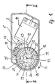
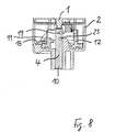
- the lock shown with a closed by a lid 1 Housing 2 serves to lock the steering spindle 3 shown in FIGS. 2 to 5 a motor vehicle by means of a locking member 4, which with a on the Steering spindle 3 attached locking sleeve 5 cooperates with locking grooves 6.
- the Steering spindle 3 and the locking sleeve 5 are not shown Enclosed casing tube on which the housing 2 is attached.
- the Locking member 4 is designed as a bolt with a rectangular cross section and in a channel 7 corresponding cross section of the housing 2 axially slidably mounted, the longitudinal axis 8 of the longitudinal axis 9 of the Steering spindle 3 cuts at right angles.
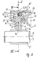
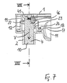
- the locking member 4 is between that shown in FIGS. 2 and 3 Locking position, in which it with its the steering spindle 3rd adjacent end 10 engages in a locking groove 6 of the locking sleeve 5, so that the Steering spindle 3 can no longer be rotated, and that of FIGS. 7 to 9 apparent unlocking position back and forth, in which the Locking member 4 engages with its end 10 in no locking groove 6 of the locking sleeve 5 and releases the steering shaft 3 so that it can be rotated.
- the control member 12 is essentially coaxial arranged to the locking member 4 and surrounds the locking member 4, is in the housing 2nd 3 in one to which the longitudinal axis 8 of the locking member channel 7 and the longitudinal axis 9 of the steering spindle 3 containing plane M parallel Level N running parallel to the longitudinal axis 8 of the locking member channel 7 Axis 13 between a coaxial to this axis 13 annular surface 14 of the Housing 2 and a coaxial to this axis 13 from Inner projections 15 of the lid 1 are rotatably mounted and is as sleeve-shaped worm wheel with an external toothing 16, in which attached one on the output shaft 17 of the electric motor 11 Drive worm 18 engages.
- the electric motor 11 can be one Twelve volt DC motor act, its direction of rotation by reversing the polarity can be reversed and which stops when
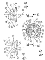
- the inner locking member 4 is provided with a first outer projection 19, with which a first inner inclined surface 20 and a first inner End surface 21 and a second inner end surface 22 of the outer control member 12 cooperate.
- the inner locking member 4 has a second outer projection 23 with which a second inner inclined surface 24 and a third inner end surface 25 and a fourth inner end surface 26 of the outer control member 12 cooperate.
- the first inclined surface 20 and the second inclined surface 24 of the control member 12 have the same slope.
- the end faces 21, 22, 25, 26 each lie in a perpendicular to the axis of rotation 13 of the control member 12 Level.
- the first inclined surface 20 of the control member 12 and the first end surface 21 and the second end surface 22 are opposite the second inclined surface 24 of the control member 12 and the third end surface 25 and the fourth end surface 26 in the direction of the axis of rotation 13 of the control member 12 by the distance H offset and extend at a distance A about the axis of rotation 13 of the Control member 12 around, which is greater than the distance A ', in which the second inclined surface 24 of the control member 12 and the third end surface 25 and the fourth end surface 26 about the axis of rotation 13 of the control member 12 extend.
- the first projection 19 and the second projection 23 of the locking member 4 are each essentially radial with respect to the axis of rotation 13 of the Control member 12 from the locking member 4, on each other with respect to the Axis of rotation 13 of the control member 12 diametrically opposite sides.
- the first projection 19 is opposite the second projection 23 of the locking member 4 exactly as far and in the same direction along the axis of rotation 13 of the Control member 12 is offset, like the first inclined surface 20 of the control member 12 and the first end surface 21 and the second end surface 22 opposite the second inclined surface 24 of the control member 12 and the third end surface 25 and the fourth end face 26, namely by the distance H in FIGS. 2 and 3 above.
- the length L of the first projection 19 of the Locking member 4 is so much larger than the length L 'of the second projection 23 of the locking member 4, as the distance A of the first inclined surface 20 of the Control member 12 and the first end surface 21 and the second end surface 22nd of the axis of rotation 13 of the control member 12 is greater than the distance A ' second inclined surface 24 of the control member 12 and the third end surface 25 and the fourth end face 26 of the axis of rotation 13 of the control member 12.
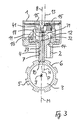
- 3 and 6 are the plane P, which is the longitudinal axis 31 of the first Projection 19 and the longitudinal axis 32 of the second projection 23 of the Includes locking member 4, and the axis of rotation 13 of the control member 12 mutually offset.
- the axis of rotation 13 of the control member 12 and its plane N run parallel to plane P at a short distance
- Control member 12 at the end 33 of the first, which is remote from the first inclined surface 20 End surface 21 and at the end 34 of the first inclined surface 20 second end surface 22, each with an inner, to the axis of rotation 13 of the control member 12 parallel stop surface 35 and 36 for the first projection 19 of the Locking member 4 and has the control member 12 on that of the second Inclined surface 24 distal end 37 of the third end surface 25 and at which the second inclined surface 24 distal end 38 of the fourth end surface 26 one each inner stop surface 39 parallel to the axis of rotation 13 of the control member 12 or 40 for the second projection 23 of the locking member 4.
- Both the first inclined surface 20 of the control member 12 and the first End surface 21 and the second end surface 22 and the second inclined surface 24 of the control member 12 and the third end surface 25 and the fourth end surface 26 together extend over a central angle ⁇ of approximately 360 °, So enclose the axis of rotation 13 of the control member 12 almost completely, namely up to the minimum distance between the two stop surfaces 35, 36 or the two stop surfaces 39, 40 from each other. Thereby extend both the first inclined surface 20 of the control member 12 and the first End surface 21 and the second end surface 22 and the second inclined surface 24 of the control member 12 and the third end surface 25 and the fourth end surface 26 each have a central angle ⁇ of approximately 120 ° and lie in FIG. 11 and 12 lower first end surface 21 and upper fourth end surface 26 therein plane R. perpendicular to the axis of rotation 13 of the control member 12
- Helical compression spring 41 Between the locking member 4 and the lid 1 of the housing 2 is one Helical compression spring 41 arranged which the first projection 19 of the Locking member 4 against the first inclined surface 20 of the control member 12 and the first end surface 21 and the second end surface 22 presses and the second Projection 23 of the locking member 4 against the second inclined surface 24 of the Control member 12 and the third end surface 25 and the fourth end surface 26 presses.
- the control member 12 is a die-cast part. It can be very economical from a suitable metallic or synthetic material manufacture with a die casting machine.
- the described steering lock for motor vehicles works as follows.
- the locking member 4 If the locking member 4 is in the locking position, then lies its first projection 19 on the first end surface 21 and its second Projection 23 on the third end surface 25 in the control member 12, as in FIG. 1 and 2 shown.
- Electric motor 11 turned on so that it drives the worm gear 18 in the direction of arrow F and control element 12 in the direction of arrow G according to FIG. 1 rotates.
- the first end surface 21 is below the first Projection 19 and the third end surface 25 under the second projection 23 runs away and the first projection 19 on the first inclined surface 20 and the second projection 23 on the second inclined surface 24 of the control member 12 passes to the second end surface 22 or the fourth End surface 26 run in the control member 12.
- the first projection 19 is reached and merges with the second end surface 22 and the second projection 23 reached and passes to the fourth end surface 26 in a not shown Rotary position of the control member 12 shortly before the rotational position, which is shown in FIG. 6 is reproduced.
- This axial displacement of the Locking member 4 begins as soon as the first projection 19 of the locking member 4 of the second end surface 22 onto the first inclined surface 20 of the control member 12 and the second projection 23 of the locking member 4 from the fourth end surface 26 runs on the second inclined surface 24 of the control member 12 and is finished, as soon as the first projection 19 from the first inclined surface 20 to the first End surface 21 and the second projection 23 from the second inclined surface 24 has passed to the third end surface 25.
- the control member 12 can then still in the direction of arrow X in the rotational position shown in FIG.
- the control member 12 can then move in freely Turn direction of arrow X to the rotary position shown in FIG. 1, if none Locking groove 6 of the locking sleeve 5 seated on the steering spindle 3 on the Locking member 4 is aligned to receive its free end 10.
- the locking member 4th by the helical compression spring 41 further in the direction of arrow V according to FIG. 4 moved to with its end 10 in one of the two adjacent locking grooves 6 engage the locking sleeve 5 and the one shown in FIGS. 2 and 3 Assume the locking position as soon as the steering shaft 3 is rotated in this way has been that the locking groove 6 is aligned with the locking member 4.
Landscapes
- Engineering & Computer Science (AREA)
- Mechanical Engineering (AREA)
- Chemical & Material Sciences (AREA)
- Combustion & Propulsion (AREA)
- Transportation (AREA)
- Lock And Its Accessories (AREA)
Applications Claiming Priority (2)
| Application Number | Priority Date | Filing Date | Title |
|---|---|---|---|
| DE10109609A DE10109609C1 (de) | 2001-02-28 | 2001-02-28 | Schloß, insbesondere zum Verriegeln der Lenkspindel eines Kraftfahrzeugs |
| DE10109609 | 2001-02-28 |
Publications (3)
| Publication Number | Publication Date |
|---|---|
| EP1236626A2 EP1236626A2 (de) | 2002-09-04 |
| EP1236626A3 EP1236626A3 (de) | 2003-09-17 |
| EP1236626B1 true EP1236626B1 (de) | 2004-07-28 |
Family
ID=7675781
Family Applications (1)
| Application Number | Title | Priority Date | Filing Date |
|---|---|---|---|
| EP01129339A Expired - Lifetime EP1236626B1 (de) | 2001-02-28 | 2001-12-17 | Schloss, insbesondere zum Verriegeln der Lenkspindel eines Kraftfahrzeugs |
Country Status (8)
| Country | Link |
|---|---|
| US (1) | US6647751B2 (ko) |
| EP (1) | EP1236626B1 (ko) |
| JP (1) | JP3881563B2 (ko) |
| KR (1) | KR100831642B1 (ko) |
| CN (1) | CN1226157C (ko) |
| AT (1) | ATE271986T1 (ko) |
| DE (2) | DE10109609C1 (ko) |
| ES (1) | ES2225393T3 (ko) |
Cited By (1)
| Publication number | Priority date | Publication date | Assignee | Title |
|---|---|---|---|---|
| CN102371970A (zh) * | 2010-08-10 | 2012-03-14 | 霍弗·霍斯贝克及弗斯特两合公司 | 用于使能移动的闭锁件移位的装置 |
Families Citing this family (40)
| Publication number | Priority date | Publication date | Assignee | Title |
|---|---|---|---|---|
| JP2002234419A (ja) * | 2001-02-09 | 2002-08-20 | Tokai Rika Co Ltd | 電子式ステアリングロック機構 |
| DE10121714C1 (de) | 2001-05-04 | 2003-01-02 | Huf Huelsbeck & Fuerst Gmbh | Schloß, insbesondere zum Verriegeln der Lenkspindel eines Kraftfahrzeugs |
| JP3810327B2 (ja) * | 2002-02-27 | 2006-08-16 | 株式会社ジェイテクト | 操舵軸のロック装置 |
| JP3808789B2 (ja) * | 2002-03-22 | 2006-08-16 | 株式会社東海理化電機製作所 | 電動ステアリングロック装置 |
| DE10247803B3 (de) * | 2002-10-14 | 2004-01-29 | Huf Hülsbeck & Fürst Gmbh & Co. Kg | Vorrichtung zum Sperren der Lenkspindel eines Kraftfahrzeugs |
| DE10247802B3 (de) | 2002-10-14 | 2004-02-05 | Huf Hülsbeck & Fürst Gmbh & Co. Kg | Vorrichtung zum Sperren der Lenkspindel eines Kraftfahrzeugs |
| JP4038132B2 (ja) * | 2003-01-31 | 2008-01-23 | 株式会社東海理化電機製作所 | 電動ステアリングロック装置 |
| JP2004231123A (ja) * | 2003-01-31 | 2004-08-19 | Tokai Rika Co Ltd | 電動ステアリングロック装置 |
| DE10320138B3 (de) * | 2003-05-06 | 2005-01-13 | Huf Hülsbeck & Fürst Gmbh & Co. Kg | Vorrichtung zum Sperren der Lenkspindel eines Kraftfahrzeugs |
| DE10320155B3 (de) * | 2003-05-06 | 2005-02-17 | Huf Hülsbeck & Fürst Gmbh & Co. Kg | Vorrichtung zum Sperren der Lenkspindel eines Kraftfahrzeugs |
| US20050120761A1 (en) * | 2003-12-03 | 2005-06-09 | Rouleau James E. | Column assembly of a vehicle having a steering column to be locked and unlocked |
| DE102004001511B4 (de) * | 2004-01-09 | 2015-02-19 | Continental Automotive Gmbh | Vorrichtung zum Arretieren einer Lenksäule eines Kraftfahrzeuges |
| US7065993B2 (en) * | 2004-06-04 | 2006-06-27 | U-Shin Ltd. | Motor-driven steering lock device |
| JP4348245B2 (ja) * | 2004-07-08 | 2009-10-21 | 株式会社東海理化電機製作所 | ステアリングロック装置 |
| DE102004043898B3 (de) * | 2004-09-10 | 2005-12-01 | Huf Hülsbeck & Fürst Gmbh & Co. Kg | Vorrichtung zum Sperren der Lenkspindel eines Kraftfahrzeugs |
| KR20070085445A (ko) * | 2004-10-26 | 2007-08-27 | 후프 노쓰 아메리카 오토모티브 파츠 엠에프지. 코프. | 비선형 조향 잠금 조립체 |
| JP3754057B1 (ja) * | 2004-10-29 | 2006-03-08 | 株式会社アルファ | 電動ステアリングロック装置 |
| ATE527141T1 (de) | 2005-03-02 | 2011-10-15 | Huf Huelsbeck & Fuerst Gmbh | Verriegelungsvorrichtung für eine lenkspindel und anwendungsspezifische integrierte schaltung hierfür |
| DE102005027777A1 (de) * | 2005-06-15 | 2006-12-21 | Huf Hülsbeck & Fürst Gmbh & Co. Kg | Verriegelungsvorrichtung für eine Lenkspindel mit wählbarer Abschaltposition bei Bewegung der Sperrbolzenanordnung in Richtung einer Freigabeendposition |
| CN100381309C (zh) * | 2005-11-24 | 2008-04-16 | 合肥昌辉汽车电子有限公司 | 汽车转向防盗装置 |
| US7762110B2 (en) * | 2006-10-06 | 2010-07-27 | U-Shin, Ltd. | Steering lock unit |
| DE102008016820A1 (de) * | 2008-04-01 | 2009-10-08 | Huf Hülsbeck & Fürst Gmbh & Co. Kg | Vorrichtung zur Ansteuerung einer Sperreinheit |
| JP5385724B2 (ja) * | 2008-08-29 | 2014-01-08 | 株式会社アルファ | ステアリングロック装置 |
| FR2952332B1 (fr) * | 2009-11-06 | 2013-11-29 | Valeo Securite Habitacle | Dispositif antivol pour colonne de direction de vehicule a super condamnation assuree par bascule intermediaire |
| JP2011121496A (ja) * | 2009-12-11 | 2011-06-23 | Alpha Corp | ステアリングロック装置 |
| US8272291B2 (en) * | 2010-01-15 | 2012-09-25 | Samuel Fasone | Steering column locking device |
| US8424348B2 (en) * | 2010-01-27 | 2013-04-23 | Strattec Security Corporation | Steering lock |
| CN102145682B (zh) * | 2011-03-31 | 2012-07-25 | 王英俊 | 车辆方向盘防盗装置 |
| DE102011116067A1 (de) * | 2011-07-22 | 2013-01-24 | Kiekert Ag | Tankklappenverriegelung mit reduzierter Anzahl von Bauteilen |
| JP5965202B2 (ja) * | 2012-04-27 | 2016-08-03 | 株式会社アルファ | ステアリングロック装置 |
| DE102013217735A1 (de) | 2012-09-07 | 2014-03-13 | Strattec Security Corporation | Lenkschloss |
| DE102013008550A1 (de) | 2013-05-16 | 2014-11-20 | Huf Hülsbeck & Fürst Gmbh & Co. Kg | Elektromechanische Verriegelungseinheit für den Fahrzeugbereich |
| DE102013114787A1 (de) | 2013-12-23 | 2015-06-25 | Huf Hülsbeck & Fürst Gmbh & Co. Kg | Antriebsanordnung einer Lenkverriegelung |
| DE102013114788A1 (de) | 2013-12-23 | 2015-06-25 | Huf Hülsbeck & Fürst Gmbh & Co. Kg | Antriebsträger für eine Antriebseinheit und elektrische Lenkverriegelung mit einem solchen Antriebsträger |
| US9731681B2 (en) * | 2014-04-29 | 2017-08-15 | Strattec Security Corporation | Steering lock |
| DE102016108565A1 (de) * | 2016-05-10 | 2017-11-16 | Huf Hülsbeck & Fürst Gmbh & Co. Kg | Umsetzungselement für eine elektrische Lenkradsperre |
| DE102016115643A1 (de) * | 2016-08-23 | 2018-03-01 | Huf Hülsbeck & Fürst Gmbh & Co. Kg | Sperrvorrichtung für eine Lenksäule eines Kraftfahrzeugs und Lenksäule mit der Sperrvorrichtung |
| JP6807762B2 (ja) * | 2017-01-31 | 2021-01-06 | 株式会社アルファ | ステアリングロック装置 |
| US20210094507A1 (en) * | 2019-09-26 | 2021-04-01 | Steering Solutions Ip Holding Corporation | Lock mechanism for steering assist system |
| RU2755356C1 (ru) * | 2020-09-28 | 2021-09-15 | Общество с ограниченной ответственностью "Титан" | Замок |
Family Cites Families (16)
| Publication number | Priority date | Publication date | Assignee | Title |
|---|---|---|---|---|
| US1736900A (en) * | 1928-01-07 | 1929-11-26 | Arthur H Hough | Steering-wheel lock for automobiles |
| US1907625A (en) * | 1930-03-24 | 1933-05-09 | Knape & Vogt Mfg Co | Showcase sliding doorlock |
| US4446709A (en) * | 1981-07-14 | 1984-05-08 | Chicago Lock Co. | Cylinder lock mechanism |
| US4581909A (en) * | 1982-05-27 | 1986-04-15 | Neiman S.A. | Cylinder lock, particularly a steering-wheel lock for a motor vehicle |
| US4583775A (en) * | 1984-05-16 | 1986-04-22 | Southco, Inc. | Latch assembly having pull-up action |
| US4671547A (en) * | 1985-07-31 | 1987-06-09 | The Eastern Company | Half turn cabinet latch with door gasket clamping capability |
| US4924685A (en) * | 1989-02-17 | 1990-05-15 | Usina Juan S | Steering wheel locking mechanisms for cars and trucks |
| DE4436326C1 (de) * | 1994-10-11 | 1995-10-19 | Huelsbeck & Fuerst | Schloß, insbesondere zum Verriegeln der Lenkspindel oder der Zahnstange des Lenkgetriebes oder der Ausgangswelle des Antriebsgetriebes eines Kraftfahrzeugs |
| DE29611043U1 (de) * | 1996-06-24 | 1996-08-29 | Huelsbeck & Fuerst | Lenkschloß für Kraftfahrzeuge |
| EP1386798B1 (en) * | 1997-03-28 | 2005-10-26 | HONDA LOCK MFG. Co., LTD. | Steering lock device |
| US6116660A (en) * | 1997-09-29 | 2000-09-12 | Southco, Inc. | Apparatus for sealing latching devices |
| DE19964173C2 (de) * | 1999-02-15 | 2001-12-13 | Valeo Deutschland Gmbh & Co | Vorrichtung zur elektrischen Verriegelung der Lenkspindel einer Lenkeinrichtung |
| DE19929435C2 (de) * | 1999-06-26 | 2002-05-23 | Huf Huelsbeck & Fuerst Gmbh | Vorrichtung zur Positionserkennung eines beweglichen Glieds in einem bei Fahrzeugen anwendbaren Verschluss |
| DE19961975C1 (de) * | 1999-12-22 | 2000-12-14 | Valeo Deutschland Gmbh & Co | Verriegelungsvorrichtung |
| DE10030688C1 (de) * | 2000-06-23 | 2001-10-18 | Huf Huelsbeck & Fuerst Gmbh | Schloß, insbesondere zum Verriegeln der Lenkspindel oder der Zahnstange des Lenkgetriebes oder der Ausgangswelle des Antriebsgetriebes eines Kraftfahrzeugs |
| DE10156335C2 (de) * | 2001-11-16 | 2003-12-24 | Huf Huelsbeck & Fuerst Gmbh | Vorrichtung zum Sperren der Lenkspindel eines Kraftfahrzeugs |
-
2001
- 2001-02-28 DE DE10109609A patent/DE10109609C1/de not_active Expired - Fee Related
- 2001-12-17 DE DE50102992T patent/DE50102992D1/de not_active Expired - Lifetime
- 2001-12-17 AT AT01129339T patent/ATE271986T1/de not_active IP Right Cessation
- 2001-12-17 ES ES01129339T patent/ES2225393T3/es not_active Expired - Lifetime
- 2001-12-17 EP EP01129339A patent/EP1236626B1/de not_active Expired - Lifetime
-
2002
- 2002-02-06 KR KR1020020006677A patent/KR100831642B1/ko active IP Right Grant
- 2002-02-06 CN CNB021034842A patent/CN1226157C/zh not_active Expired - Fee Related
- 2002-02-20 US US10/077,918 patent/US6647751B2/en not_active Expired - Fee Related
- 2002-02-25 JP JP2002047455A patent/JP3881563B2/ja not_active Expired - Fee Related
Cited By (1)
| Publication number | Priority date | Publication date | Assignee | Title |
|---|---|---|---|---|
| CN102371970A (zh) * | 2010-08-10 | 2012-03-14 | 霍弗·霍斯贝克及弗斯特两合公司 | 用于使能移动的闭锁件移位的装置 |
Also Published As
| Publication number | Publication date |
|---|---|
| DE50102992D1 (de) | 2004-09-02 |
| CN1373061A (zh) | 2002-10-09 |
| KR20020070784A (ko) | 2002-09-11 |
| DE10109609C1 (de) | 2002-10-10 |
| EP1236626A3 (de) | 2003-09-17 |
| JP2002326559A (ja) | 2002-11-12 |
| ATE271986T1 (de) | 2004-08-15 |
| EP1236626A2 (de) | 2002-09-04 |
| US20020116962A1 (en) | 2002-08-29 |
| ES2225393T3 (es) | 2005-03-16 |
| CN1226157C (zh) | 2005-11-09 |
| US6647751B2 (en) | 2003-11-18 |
| KR100831642B1 (ko) | 2008-05-22 |
| JP3881563B2 (ja) | 2007-02-14 |
Similar Documents
| Publication | Publication Date | Title |
|---|---|---|
| EP1236626B1 (de) | Schloss, insbesondere zum Verriegeln der Lenkspindel eines Kraftfahrzeugs | |
| EP1363815B1 (de) | Schloss, insbesondere zum verriegeln der lenkspindel eines kraftfahrzeugs | |
| EP1167134B1 (de) | Schloss, insbesondere zum Verriegeln der Lenkspindel oder der Zahnstange des Lenkgetriebes oder der Ausgangswelle des Antriebsgetriebes eines Kraftfahrzeugs | |
| EP1110828B1 (de) | Verriegelungsvorrichtung | |
| EP1558474B1 (de) | Vorrichtung zum sperren der lenkspindel eines kraftfahrzeugs | |
| DE10247802B3 (de) | Vorrichtung zum Sperren der Lenkspindel eines Kraftfahrzeugs | |
| EP2029394B1 (de) | Bordmonitoreinrichtung | |
| EP1725437B1 (de) | Vorrichtung zum sperren der lenkspindel eines kraftfahrzeugs | |
| DE10320154B3 (de) | Vorrichtung zum Sperren der Lenkspindel eines Kraftfahrzeugs | |
| EP1383669B1 (de) | Vorrichtung zum sperren der lenkspindel eines kraftfahrzeugs | |
| DE3616122C2 (de) | Lenk- und Zündschloß | |
| DE4436326C1 (de) | Schloß, insbesondere zum Verriegeln der Lenkspindel oder der Zahnstange des Lenkgetriebes oder der Ausgangswelle des Antriebsgetriebes eines Kraftfahrzeugs | |
| DE3738416A1 (de) | Antrieb zum verstellen eines glieds, insbesondere eines riegelelements, das zum schliessmechanismus eines einer oeffnung in einer kraftfahrzeugkarosserie zugeordneten abdeckelements gehoert | |
| DE3941352C2 (de) | Elektromotorisches Stellglied | |
| DE3439705C2 (ko) | ||
| EP1106451A2 (de) | Elektronisches Lenkschloss und elektronischer Zündanlassschalter für Kraftfahrzeuge | |
| DE4430432A1 (de) | Elektrisch betätigbares Schloß, insbesondere für eine Zentralverriegelungsanlage eines Fahrzeugs | |
| WO2005019004A1 (de) | Elektronisches lenkschloss und elektronischer zündanlassschlater für kraftfahrzeuge | |
| DE4407912C2 (de) | Elektromechanisches Schloß | |
| EP0967350A1 (de) | Elektromotorischer Stellantrieb für ein Kraftfahrzeugschloss | |
| EP1403104B1 (de) | Einstellbarer Drehstab-Stabilisator für Radaufhängung | |
| DE102005021050B3 (de) | Vorrichtung zum Sperren der Lenkspindel eines Kraftfahrzeugs | |
| DE19526660A1 (de) | Elektromechanisches Schloß | |
| DE2825873B2 (de) | Kraftfahrzeug-Lenkschloß | |
| DE2651496C3 (de) | Kraftfahrzeug-Lenkschloß |
Legal Events
| Date | Code | Title | Description |
|---|---|---|---|
| PUAI | Public reference made under article 153(3) epc to a published international application that has entered the european phase |
Free format text: ORIGINAL CODE: 0009012 |
|
| AK | Designated contracting states |
Kind code of ref document: A2 Designated state(s): AT BE CH CY DE DK ES FI FR GB GR IE IT LI LU MC NL PT SE TR |
|
| AX | Request for extension of the european patent |
Free format text: AL;LT;LV;MK;RO;SI |
|
| PUAL | Search report despatched |
Free format text: ORIGINAL CODE: 0009013 |
|
| AK | Designated contracting states |
Kind code of ref document: A3 Designated state(s): AT BE CH CY DE DK ES FI FR GB GR IE IT LI LU MC NL PT SE TR |
|
| AX | Request for extension of the european patent |
Extension state: AL LT LV MK RO SI |
|
| 17P | Request for examination filed |
Effective date: 20030905 |
|
| GRAP | Despatch of communication of intention to grant a patent |
Free format text: ORIGINAL CODE: EPIDOSNIGR1 |
|
| GRAS | Grant fee paid |
Free format text: ORIGINAL CODE: EPIDOSNIGR3 |
|
| AKX | Designation fees paid |
Designated state(s): AT BE CH CY DE DK ES FI FR GB GR IE IT LI LU MC NL PT SE TR |
|
| GRAA | (expected) grant |
Free format text: ORIGINAL CODE: 0009210 |
|
| AK | Designated contracting states |
Kind code of ref document: B1 Designated state(s): AT BE CH CY DE DK ES FI FR GB GR IE IT LI LU MC NL PT SE TR |
|
| PG25 | Lapsed in a contracting state [announced via postgrant information from national office to epo] |
Ref country code: CY Free format text: LAPSE BECAUSE OF FAILURE TO SUBMIT A TRANSLATION OF THE DESCRIPTION OR TO PAY THE FEE WITHIN THE PRESCRIBED TIME-LIMIT Effective date: 20040728 Ref country code: NL Free format text: LAPSE BECAUSE OF FAILURE TO SUBMIT A TRANSLATION OF THE DESCRIPTION OR TO PAY THE FEE WITHIN THE PRESCRIBED TIME-LIMIT Effective date: 20040728 Ref country code: IE Free format text: LAPSE BECAUSE OF FAILURE TO SUBMIT A TRANSLATION OF THE DESCRIPTION OR TO PAY THE FEE WITHIN THE PRESCRIBED TIME-LIMIT Effective date: 20040728 Ref country code: FI Free format text: LAPSE BECAUSE OF FAILURE TO SUBMIT A TRANSLATION OF THE DESCRIPTION OR TO PAY THE FEE WITHIN THE PRESCRIBED TIME-LIMIT Effective date: 20040728 Ref country code: TR Free format text: LAPSE BECAUSE OF FAILURE TO SUBMIT A TRANSLATION OF THE DESCRIPTION OR TO PAY THE FEE WITHIN THE PRESCRIBED TIME-LIMIT Effective date: 20040728 |
|
| REG | Reference to a national code |
Ref country code: GB Ref legal event code: FG4D Free format text: NOT ENGLISH |
|
| REG | Reference to a national code |
Ref country code: CH Ref legal event code: EP |
|
| GBT | Gb: translation of ep patent filed (gb section 77(6)(a)/1977) |
Effective date: 20040728 |
|
| REG | Reference to a national code |
Ref country code: IE Ref legal event code: FG4D Free format text: GERMAN |
|
| REF | Corresponds to: |
Ref document number: 50102992 Country of ref document: DE Date of ref document: 20040902 Kind code of ref document: P |
|
| PG25 | Lapsed in a contracting state [announced via postgrant information from national office to epo] |
Ref country code: GR Free format text: LAPSE BECAUSE OF FAILURE TO SUBMIT A TRANSLATION OF THE DESCRIPTION OR TO PAY THE FEE WITHIN THE PRESCRIBED TIME-LIMIT Effective date: 20041028 Ref country code: DK Free format text: LAPSE BECAUSE OF FAILURE TO SUBMIT A TRANSLATION OF THE DESCRIPTION OR TO PAY THE FEE WITHIN THE PRESCRIBED TIME-LIMIT Effective date: 20041028 Ref country code: SE Free format text: LAPSE BECAUSE OF FAILURE TO SUBMIT A TRANSLATION OF THE DESCRIPTION OR TO PAY THE FEE WITHIN THE PRESCRIBED TIME-LIMIT Effective date: 20041028 |
|
| PG25 | Lapsed in a contracting state [announced via postgrant information from national office to epo] |
Ref country code: AT Free format text: LAPSE BECAUSE OF NON-PAYMENT OF DUE FEES Effective date: 20041217 |
|
| PG25 | Lapsed in a contracting state [announced via postgrant information from national office to epo] |
Ref country code: MC Free format text: LAPSE BECAUSE OF NON-PAYMENT OF DUE FEES Effective date: 20041231 Ref country code: LU Free format text: LAPSE BECAUSE OF NON-PAYMENT OF DUE FEES Effective date: 20041231 Ref country code: BE Free format text: LAPSE BECAUSE OF NON-PAYMENT OF DUE FEES Effective date: 20041231 |
|
| NLV1 | Nl: lapsed or annulled due to failure to fulfill the requirements of art. 29p and 29m of the patents act | ||
| REG | Reference to a national code |
Ref country code: ES Ref legal event code: FG2A Ref document number: 2225393 Country of ref document: ES Kind code of ref document: T3 |
|
| REG | Reference to a national code |
Ref country code: IE Ref legal event code: FD4D |
|
| ET | Fr: translation filed | ||
| PLBE | No opposition filed within time limit |
Free format text: ORIGINAL CODE: 0009261 |
|
| STAA | Information on the status of an ep patent application or granted ep patent |
Free format text: STATUS: NO OPPOSITION FILED WITHIN TIME LIMIT |
|
| ET1 | Fr: translation filed ** revision of the translation of the patent or the claims | ||
| BERE | Be: lapsed |
Owner name: HUF HULSBECK & FURST G.M.B.H. & CO. KG Effective date: 20041231 |
|
| 26N | No opposition filed |
Effective date: 20050429 |
|
| PG25 | Lapsed in a contracting state [announced via postgrant information from national office to epo] |
Ref country code: CH Free format text: LAPSE BECAUSE OF NON-PAYMENT OF DUE FEES Effective date: 20051231 Ref country code: LI Free format text: LAPSE BECAUSE OF NON-PAYMENT OF DUE FEES Effective date: 20051231 |
|
| REG | Reference to a national code |
Ref country code: CH Ref legal event code: PL |
|
| BERE | Be: lapsed |
Owner name: HULSBECK & FURST G.M.B.H. & CO. K.G. *HUF Effective date: 20041231 |
|
| PG25 | Lapsed in a contracting state [announced via postgrant information from national office to epo] |
Ref country code: PT Free format text: LAPSE BECAUSE OF NON-PAYMENT OF DUE FEES Effective date: 20041228 |
|
| PGFP | Annual fee paid to national office [announced via postgrant information from national office to epo] |
Ref country code: ES Payment date: 20091218 Year of fee payment: 9 |
|
| PGFP | Annual fee paid to national office [announced via postgrant information from national office to epo] |
Ref country code: GB Payment date: 20091221 Year of fee payment: 9 Ref country code: IT Payment date: 20091223 Year of fee payment: 9 |
|
| GBPC | Gb: european patent ceased through non-payment of renewal fee |
Effective date: 20101217 |
|
| PG25 | Lapsed in a contracting state [announced via postgrant information from national office to epo] |
Ref country code: GB Free format text: LAPSE BECAUSE OF NON-PAYMENT OF DUE FEES Effective date: 20101217 |
|
| PG25 | Lapsed in a contracting state [announced via postgrant information from national office to epo] |
Ref country code: IT Free format text: LAPSE BECAUSE OF NON-PAYMENT OF DUE FEES Effective date: 20101217 |
|
| REG | Reference to a national code |
Ref country code: ES Ref legal event code: FD2A Effective date: 20120206 |
|
| PG25 | Lapsed in a contracting state [announced via postgrant information from national office to epo] |
Ref country code: ES Free format text: LAPSE BECAUSE OF NON-PAYMENT OF DUE FEES Effective date: 20101218 |
|
| REG | Reference to a national code |
Ref country code: FR Ref legal event code: PLFP Year of fee payment: 15 |
|
| REG | Reference to a national code |
Ref country code: FR Ref legal event code: PLFP Year of fee payment: 16 |
|
| REG | Reference to a national code |
Ref country code: FR Ref legal event code: PLFP Year of fee payment: 17 |
|
| PGFP | Annual fee paid to national office [announced via postgrant information from national office to epo] |
Ref country code: DE Payment date: 20191217 Year of fee payment: 19 |
|
| PGFP | Annual fee paid to national office [announced via postgrant information from national office to epo] |
Ref country code: FR Payment date: 20191218 Year of fee payment: 19 |
|
| REG | Reference to a national code |
Ref country code: DE Ref legal event code: R119 Ref document number: 50102992 Country of ref document: DE |
|
| PG25 | Lapsed in a contracting state [announced via postgrant information from national office to epo] |
Ref country code: FR Free format text: LAPSE BECAUSE OF NON-PAYMENT OF DUE FEES Effective date: 20201231 |
|
| PG25 | Lapsed in a contracting state [announced via postgrant information from national office to epo] |
Ref country code: DE Free format text: LAPSE BECAUSE OF NON-PAYMENT OF DUE FEES Effective date: 20210701 |