EP1234671B1 - Ink jet head, producing method therefor and ink jet recording apparatus - Google Patents
Ink jet head, producing method therefor and ink jet recording apparatus Download PDFInfo
- Publication number
- EP1234671B1 EP1234671B1 EP02003895A EP02003895A EP1234671B1 EP 1234671 B1 EP1234671 B1 EP 1234671B1 EP 02003895 A EP02003895 A EP 02003895A EP 02003895 A EP02003895 A EP 02003895A EP 1234671 B1 EP1234671 B1 EP 1234671B1
- Authority
- EP
- European Patent Office
- Prior art keywords
- flow path
- ink jet
- jet head
- ink
- forming member
- Prior art date
- Legal status (The legal status is an assumption and is not a legal conclusion. Google has not performed a legal analysis and makes no representation as to the accuracy of the status listed.)
- Expired - Lifetime
Links
- 238000000034 method Methods 0.000 title claims description 19
- 239000000758 substrate Substances 0.000 claims abstract description 80
- 239000007788 liquid Substances 0.000 claims abstract description 76
- 238000007599 discharging Methods 0.000 claims abstract description 12
- 239000011347 resin Substances 0.000 claims description 30
- 229920005989 resin Polymers 0.000 claims description 30
- 230000001965 increasing effect Effects 0.000 claims description 29
- 239000012260 resinous material Substances 0.000 claims description 19
- 229920002614 Polyether block amide Polymers 0.000 claims description 14
- 239000011248 coating agent Substances 0.000 claims description 14
- 238000000576 coating method Methods 0.000 claims description 14
- 238000000059 patterning Methods 0.000 claims description 7
- 239000003822 epoxy resin Substances 0.000 claims description 6
- 229920000647 polyepoxide Polymers 0.000 claims description 6
- 239000000126 substance Substances 0.000 claims description 6
- 238000004380 ashing Methods 0.000 claims description 3
- QVGXLLKOCUKJST-UHFFFAOYSA-N atomic oxygen Chemical compound [O] QVGXLLKOCUKJST-UHFFFAOYSA-N 0.000 claims description 3
- 125000002091 cationic group Chemical group 0.000 claims description 3
- 238000004519 manufacturing process Methods 0.000 claims description 3
- 239000001301 oxygen Substances 0.000 claims description 3
- 229910052760 oxygen Inorganic materials 0.000 claims description 3
- 229920001169 thermoplastic Polymers 0.000 claims description 2
- 239000004416 thermosoftening plastic Substances 0.000 claims description 2
- 239000000976 ink Substances 0.000 description 300
- 239000010410 layer Substances 0.000 description 136
- 230000008569 process Effects 0.000 description 9
- 230000015572 biosynthetic process Effects 0.000 description 8
- 230000033001 locomotion Effects 0.000 description 6
- 230000008961 swelling Effects 0.000 description 6
- 239000003086 colorant Substances 0.000 description 5
- 230000002035 prolonged effect Effects 0.000 description 5
- 230000004888 barrier function Effects 0.000 description 4
- 238000003780 insertion Methods 0.000 description 4
- 230000037431 insertion Effects 0.000 description 4
- 239000000463 material Substances 0.000 description 4
- 244000126211 Hericium coralloides Species 0.000 description 3
- 238000005530 etching Methods 0.000 description 3
- 239000010408 film Substances 0.000 description 3
- 239000012528 membrane Substances 0.000 description 3
- 230000005499 meniscus Effects 0.000 description 3
- 229920002120 photoresistant polymer Polymers 0.000 description 3
- 238000011084 recovery Methods 0.000 description 3
- 238000003860 storage Methods 0.000 description 3
- 238000012360 testing method Methods 0.000 description 3
- VYPSYNLAJGMNEJ-UHFFFAOYSA-N Silicium dioxide Chemical compound O=[Si]=O VYPSYNLAJGMNEJ-UHFFFAOYSA-N 0.000 description 2
- 238000003491 array Methods 0.000 description 2
- 238000009835 boiling Methods 0.000 description 2
- 230000007812 deficiency Effects 0.000 description 2
- 230000008021 deposition Effects 0.000 description 2
- 239000000428 dust Substances 0.000 description 2
- 229920001971 elastomer Polymers 0.000 description 2
- 239000007789 gas Substances 0.000 description 2
- 238000010438 heat treatment Methods 0.000 description 2
- 238000005192 partition Methods 0.000 description 2
- 230000002093 peripheral effect Effects 0.000 description 2
- 229920000642 polymer Polymers 0.000 description 2
- 238000001454 recorded image Methods 0.000 description 2
- 239000004593 Epoxy Substances 0.000 description 1
- 230000002159 abnormal effect Effects 0.000 description 1
- 238000009825 accumulation Methods 0.000 description 1
- 230000004913 activation Effects 0.000 description 1
- 125000003118 aryl group Chemical group 0.000 description 1
- 230000008033 biological extinction Effects 0.000 description 1
- 230000005540 biological transmission Effects 0.000 description 1
- 239000003990 capacitor Substances 0.000 description 1
- 230000008859 change Effects 0.000 description 1
- 229910052681 coesite Inorganic materials 0.000 description 1
- 150000001875 compounds Chemical class 0.000 description 1
- 229910052906 cristobalite Inorganic materials 0.000 description 1
- 238000005520 cutting process Methods 0.000 description 1
- 238000011161 development Methods 0.000 description 1
- 230000018109 developmental process Effects 0.000 description 1
- 238000004090 dissolution Methods 0.000 description 1
- 230000000694 effects Effects 0.000 description 1
- 238000002474 experimental method Methods 0.000 description 1
- 238000010304 firing Methods 0.000 description 1
- 230000004992 fission Effects 0.000 description 1
- 230000005484 gravity Effects 0.000 description 1
- 239000012761 high-performance material Substances 0.000 description 1
- 230000001939 inductive effect Effects 0.000 description 1
- 238000009413 insulation Methods 0.000 description 1
- 239000002184 metal Substances 0.000 description 1
- 238000002161 passivation Methods 0.000 description 1
- 239000012466 permeate Substances 0.000 description 1
- 230000001681 protective effect Effects 0.000 description 1
- 239000011241 protective layer Substances 0.000 description 1
- 238000009877 rendering Methods 0.000 description 1
- 230000004044 response Effects 0.000 description 1
- HBMJWWWQQXIZIP-UHFFFAOYSA-N silicon carbide Chemical compound [Si+]#[C-] HBMJWWWQQXIZIP-UHFFFAOYSA-N 0.000 description 1
- 229910010271 silicon carbide Inorganic materials 0.000 description 1
- 239000000377 silicon dioxide Substances 0.000 description 1
- 230000007480 spreading Effects 0.000 description 1
- 238000003892 spreading Methods 0.000 description 1
- 230000004936 stimulating effect Effects 0.000 description 1
- 229910052682 stishovite Inorganic materials 0.000 description 1
- 239000010409 thin film Substances 0.000 description 1
- 229910052905 tridymite Inorganic materials 0.000 description 1
- XLYOFNOQVPJJNP-UHFFFAOYSA-N water Substances O XLYOFNOQVPJJNP-UHFFFAOYSA-N 0.000 description 1
Images


Classifications
-
- B—PERFORMING OPERATIONS; TRANSPORTING
- B41—PRINTING; LINING MACHINES; TYPEWRITERS; STAMPS
- B41J—TYPEWRITERS; SELECTIVE PRINTING MECHANISMS, i.e. MECHANISMS PRINTING OTHERWISE THAN FROM A FORME; CORRECTION OF TYPOGRAPHICAL ERRORS
- B41J2/00—Typewriters or selective printing mechanisms characterised by the printing or marking process for which they are designed
- B41J2/005—Typewriters or selective printing mechanisms characterised by the printing or marking process for which they are designed characterised by bringing liquid or particles selectively into contact with a printing material
- B41J2/01—Ink jet
- B41J2/135—Nozzles
- B41J2/14—Structure thereof only for on-demand ink jet heads
-
- B—PERFORMING OPERATIONS; TRANSPORTING
- B41—PRINTING; LINING MACHINES; TYPEWRITERS; STAMPS
- B41J—TYPEWRITERS; SELECTIVE PRINTING MECHANISMS, i.e. MECHANISMS PRINTING OTHERWISE THAN FROM A FORME; CORRECTION OF TYPOGRAPHICAL ERRORS
- B41J2/00—Typewriters or selective printing mechanisms characterised by the printing or marking process for which they are designed
- B41J2/005—Typewriters or selective printing mechanisms characterised by the printing or marking process for which they are designed characterised by bringing liquid or particles selectively into contact with a printing material
- B41J2/01—Ink jet
- B41J2/135—Nozzles
- B41J2/16—Production of nozzles
- B41J2/1621—Manufacturing processes
- B41J2/1631—Manufacturing processes photolithography
-
- B—PERFORMING OPERATIONS; TRANSPORTING
- B41—PRINTING; LINING MACHINES; TYPEWRITERS; STAMPS
- B41J—TYPEWRITERS; SELECTIVE PRINTING MECHANISMS, i.e. MECHANISMS PRINTING OTHERWISE THAN FROM A FORME; CORRECTION OF TYPOGRAPHICAL ERRORS
- B41J2/00—Typewriters or selective printing mechanisms characterised by the printing or marking process for which they are designed
- B41J2/005—Typewriters or selective printing mechanisms characterised by the printing or marking process for which they are designed characterised by bringing liquid or particles selectively into contact with a printing material
- B41J2/01—Ink jet
- B41J2/135—Nozzles
- B41J2/14—Structure thereof only for on-demand ink jet heads
- B41J2/14016—Structure of bubble jet print heads
- B41J2/14088—Structure of heating means
- B41J2/14112—Resistive element
- B41J2/14129—Layer structure
-
- B—PERFORMING OPERATIONS; TRANSPORTING
- B41—PRINTING; LINING MACHINES; TYPEWRITERS; STAMPS
- B41J—TYPEWRITERS; SELECTIVE PRINTING MECHANISMS, i.e. MECHANISMS PRINTING OTHERWISE THAN FROM A FORME; CORRECTION OF TYPOGRAPHICAL ERRORS
- B41J2/00—Typewriters or selective printing mechanisms characterised by the printing or marking process for which they are designed
- B41J2/005—Typewriters or selective printing mechanisms characterised by the printing or marking process for which they are designed characterised by bringing liquid or particles selectively into contact with a printing material
- B41J2/01—Ink jet
- B41J2/135—Nozzles
- B41J2/16—Production of nozzles
- B41J2/1601—Production of bubble jet print heads
- B41J2/1603—Production of bubble jet print heads of the front shooter type
-
- B—PERFORMING OPERATIONS; TRANSPORTING
- B41—PRINTING; LINING MACHINES; TYPEWRITERS; STAMPS
- B41J—TYPEWRITERS; SELECTIVE PRINTING MECHANISMS, i.e. MECHANISMS PRINTING OTHERWISE THAN FROM A FORME; CORRECTION OF TYPOGRAPHICAL ERRORS
- B41J2/00—Typewriters or selective printing mechanisms characterised by the printing or marking process for which they are designed
- B41J2/005—Typewriters or selective printing mechanisms characterised by the printing or marking process for which they are designed characterised by bringing liquid or particles selectively into contact with a printing material
- B41J2/01—Ink jet
- B41J2/135—Nozzles
- B41J2/16—Production of nozzles
- B41J2/1621—Manufacturing processes
- B41J2/1623—Manufacturing processes bonding and adhesion
-
- B—PERFORMING OPERATIONS; TRANSPORTING
- B41—PRINTING; LINING MACHINES; TYPEWRITERS; STAMPS
- B41J—TYPEWRITERS; SELECTIVE PRINTING MECHANISMS, i.e. MECHANISMS PRINTING OTHERWISE THAN FROM A FORME; CORRECTION OF TYPOGRAPHICAL ERRORS
- B41J2/00—Typewriters or selective printing mechanisms characterised by the printing or marking process for which they are designed
- B41J2/005—Typewriters or selective printing mechanisms characterised by the printing or marking process for which they are designed characterised by bringing liquid or particles selectively into contact with a printing material
- B41J2/01—Ink jet
- B41J2/135—Nozzles
- B41J2/16—Production of nozzles
- B41J2/1621—Manufacturing processes
- B41J2/1626—Manufacturing processes etching
- B41J2/1629—Manufacturing processes etching wet etching
-
- B—PERFORMING OPERATIONS; TRANSPORTING
- B41—PRINTING; LINING MACHINES; TYPEWRITERS; STAMPS
- B41J—TYPEWRITERS; SELECTIVE PRINTING MECHANISMS, i.e. MECHANISMS PRINTING OTHERWISE THAN FROM A FORME; CORRECTION OF TYPOGRAPHICAL ERRORS
- B41J2/00—Typewriters or selective printing mechanisms characterised by the printing or marking process for which they are designed
- B41J2/005—Typewriters or selective printing mechanisms characterised by the printing or marking process for which they are designed characterised by bringing liquid or particles selectively into contact with a printing material
- B41J2/01—Ink jet
- B41J2/135—Nozzles
- B41J2/16—Production of nozzles
- B41J2/1621—Manufacturing processes
- B41J2/164—Manufacturing processes thin film formation
- B41J2/1645—Manufacturing processes thin film formation thin film formation by spincoating
-
- B—PERFORMING OPERATIONS; TRANSPORTING
- B41—PRINTING; LINING MACHINES; TYPEWRITERS; STAMPS
- B41J—TYPEWRITERS; SELECTIVE PRINTING MECHANISMS, i.e. MECHANISMS PRINTING OTHERWISE THAN FROM A FORME; CORRECTION OF TYPOGRAPHICAL ERRORS
- B41J2/00—Typewriters or selective printing mechanisms characterised by the printing or marking process for which they are designed
- B41J2/005—Typewriters or selective printing mechanisms characterised by the printing or marking process for which they are designed characterised by bringing liquid or particles selectively into contact with a printing material
- B41J2/01—Ink jet
- B41J2/135—Nozzles
- B41J2/14—Structure thereof only for on-demand ink jet heads
- B41J2002/14403—Structure thereof only for on-demand ink jet heads including a filter
Definitions
- the present invention relates to an ink jet head for forming an image by discharging ink (liquid) for deposition onto a recording medium, and more particularly to an ink jet head provided with a substrate bearing a discharge pressure generating element for generating a pressure for discharging ink, a flow path forming member adhered to the substrate for constituting an ink flow path, and a jointing layer for increasing the adhesion force between the substrate and the flow path forming member.
- the ink jet recording method of discharging ink from a discharge port onto a recording medium for forming a character or an image is recently employed widely as it is a non-impact recording system of low noise level capable of highspeed recording operation at a high density.
- the ink jet recording apparatus is provided with an ink jet head, a carriage for supporting such ink jet head, drive means for such carriage, conveying means for conveying a recording medium, and control means for controlling these components.
- the apparatus executing the recording operation under the movement of the carriage is called serial type.
- the apparatus executing the recording operation by the conveying operation of the recording medium, without the movement of the ink jet head is called line type.
- the ink jet head is provided with a plurality of nozzles arranged over the entire width of the recording medium.
- the ink jet head for the ink discharge pressure generating element for generating the pressure for discharging the ink droplet from the discharge port, there are known an electromechanical converting element such as a piezo element, an electrothermal converting element such as a heat generating resistor, or an electromagnetic wave-mechanical converting element or an electromagnetic wave-thermal converting element utilizing electric wave or laser light.
- the ink jet head of so-called bubble jet method utilizing a heat generating resistor for the ink discharge pressure generating element and inducing film boiling in the ink for generating a bubble thereby discharging ink, is effective for high-definition recording because the pressure generating elements can be arranged at a high density.
- Such ink jet head is generally provided with plural discharge ports, plural discharge pressure generating elements, and flow paths for guiding the ink, supplied from an ink supply system, through the discharge pressure generating elements to the discharge ports.
- the Japanese Patent Application Laid-open No. 61-154947 discloses a method of forming a flow path pattern with soluble resin on a substrate bearing a discharge pressure generating element, then forming thereon and hardening a resin layer such as of epoxy resin so as to cover the flow path pattern, and, after the cutting of the substrate, dissolving out the soluble resin.
- the Japanese Patent Application Laid-open No. 3-184868 discloses that it is effective to employ a cationic polymerized and hardened substance of an aromatic epoxy compound as the covering resin for the flow path pattern.
- the adjoining of the substrate bearing the discharge pressure generating element and the flow path forming member is by the adhesion force of the resin constituting the flow path forming member.
- the flow path is constantly filled with the ink in the normal state of use, so that the periphery of the adjoining portion between the substrate bearing the ink discharge pressure generating element and the flow path forming member is in contact with the ink. Therefore, if the adjoining is achieved by the adhesion force only of the resinous material constituting the flow path forming member, the adhesion of the adjoining portion may be deteriorated in time by the influence of the ink.
- weakly alkaline ink may be employed for meeting such requirements. Particularly in case of such weakly alkaline ink, it may become difficult to maintain the adhesion force between the substrate bearing the ink discharge pressure generating element and the flow path forming member over a prolonged period.
- bubble jet head in order to suppress damage in the heat generating resistor etc. by electroerosion caused by the ink or by cavitation at the extinction of the bubble, it is common to form an inorganic insulation layer composed for example of SiN or SiO 2 and an anticavitation layer composed for example of Ta particularly on the heat generating resistor.
- Such Ta layer has a lower adhesion force than the SiN layer to the resinous material constituting the flow path forming member. For this reason, the flow path forming member may be peeled off from the Ta layer under severe conditions.
- FIGs. 20A and 20B are respectively a horizontal cross-sectional view partly showing the vicinity of the flow path of such ink jet head and a cross-sectional view along a line 20B-20B in Fig. 20A.
- Such ink jet head is provided, on a substrate 51, with a flow path wall 61 and a ceiling portion (not shown) formed thereon and having a discharge port 59, by the aforementioned flow path forming member 58 of a resinous material.
- the discharge ports 59 are opened in opposed relationship to plural ink discharge pressure generating elements (not shown) provided on the substrate 51.
- the flow path wall 61 is formed in plural units in comb-tooth shape, and, between the adjacent flow path walls, there is formed a flow path for guiding the ink from the lower side of Fig. 20A onto each ink discharge pressure generating element.
- At the entrance of each flow path there are formed vertically extending two pillars 62 with a predetermined gap therebetween, for example in order to prevent dust intrusion into the flow path.
- the flow path forming member 58 is adjoined to the substrate 51 across an adhesion layer 56. Stated differently, the adhesion layer 56 is formed between the flow path forming member 58 and the substrate 51. In such configuration, if the adhesion layer 56 is formed over a planar area wider than the flow path forming member 58, there is formed, in the flow path, a step difference at the boundary between an area bearing the adhesion layer 56 and an area lacking the adhesion layer 56. Such step difference may complicate the flowability of the ink in the flow path and render it unstable, thereby hindering the desired stable ink flow.
- the adhesion layer 56 is provided on the ink discharge pressure generating element, loss in the transmission of the discharge energy to the ink becomes large since the discharge energy from the ink discharge pressure generating element has to be transmitted to the ink through the adhesion layer 56. Also the discharge energy may apply a force or heat to the adhesion layer 56, thereby stimulating peeling thereof. Therefore, the adhesion layer 56 is preferably provided in a planar area excluding the area of the ink discharge pressure generating element. For this reason, the adhesion layer 56 is conventionally provided in a planar area narrower than the flow path forming member 58.
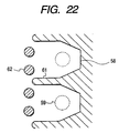
- Figs. 21A, 21B and 33 are respectively a lateral cross-sectional view of a conventional ink jet head, a magnified view of an adjoining portion of the flow path forming member 58 to the substrate 51, and a partial horizontal cross-sectional view of the vicinity of the flow path.
- an ink supply aperture 66 is formed by an etching process employing an ink supply aperture mask 53.
- the SiN layer 54 there is adjoined, across an adhesion layer 56, the flow path forming member 58 which constitutes the flow path wall 61 forming the flow path and the ceiling portion including the discharge port 59.
- the flow path forming member 58 composed of a resinous composition may be swelled by prolonged contact with the ink. Such swelling generates, in the flow path forming member 58, a stress spreading from the center to the peripheral part, as indicated by an arrow in Fig. 21A and 21B, whereby a stress is generated in the adjoining portion between the flow path forming member 58 and the substrate 51 from the interior toward the exterior so as to induce peeling of the flow path forming member 58. Such stress tends to be particularly concentrated in a front end portion of the flow path wall 61 in a direction toward the ink supply aperture 60.
- a portion of the flow path forming member 58 is directly adjoined to the SiN layer 54 without the adhesion layer 56 therebetween in the vicinity of the front end of the liquid path wall 61 as explained in the foregoing, so that the peeling of the flow path forming member 58 may occur in such portion as illustrated in Fig. 21B.
- the flow path forming member 58 will have a larger contact area with the ink, and a large stress may be generated by swelling.
- the ink flow is a factor causing the physical stress in the flow path forming member 58.
- the ink flow applies a physical stress to the flow path forming member 58.
- Such stress also tends to be concentrated in the front end portion of the flow path wall 61 in case it is formed in comb-tooth shape.
- document EP-A-0 863 005 shows a generic ink jet head having an adhesion interface between a silicon carbide layer of a thin film substrate and a polymer ink barrier layer in the vicinity of ink chambers formed in the polymer ink barrier layer. Orifices are provided for discharging ink by means of ink firing resistors.
- the object of the invention is to provide an ink jet head with an increased life time with low influence on the ink flowability.
- An ink jet head comprises :
- the adhesion layer may be so formed as to overflow from the flow path forming member only in a portion where the stress is concentrated, so that the overflowing portion into the liquid flow path need not be made large thereby minimizing the influence on the flowability of the liquid.
- the ink jet head of the aforementioned configuration there may be generated a stress by the swelling of the flow path forming member, principally in a direction from the common liquid chamber toward the peripheral portions. Consequently, the stress generated by the swelling is concentrated at the end portion of the flow path wall extending toward the common liquid chamber, in such a direction as to induce peeling of the flow path wall. Also the stress tends to be generated at such end portion of the flow path wall by the ink flow. Therefore, by forming the adhesion layer at the end portion of the flow path wall, over a planar area wider than the adjoining area between the flow path wall and the substrate, it is rendered possible to increase the adhesion force between the end portion of the flow path wall and the substrate, thereby effectively suppressing the peeling phenomenon in such portion.
- the overflowing portion of the adhesion layer from the flow path forming member is present at the root portion of the flow path relatively distant from the discharge port for liquid discharge, thus having a relatively small influence on the liquid flowability in the flow path.
- the adhesion layer is preferably formed within an area included in the adjoining area of the flow path wall at the root side thereof, so as not to overflow from the flow path forming member.
- the flow path wall is very narrow in width, the adhesion layer may be dispensed with at the root side of the flow path wall. Even in such case, the flow path wall is difficult to be peeled off as the adhesion force thereof is increased by the adhesion layer at the front end portion thereof.
- the adhesion layer may be formed in a belt-like shape so as to pass through the adjoining portions of the front end portions of such plural flow path walls. Such configuration allows to effectively increase the adhesion force between the front end portions of the flow path walls and the substrate by the adhesion layer of a sufficient area even for the flow path walls formed with a very small pitch.
- a pillar composed of the flow path forming member, in the vicinity of the entrance of the flow path and in an area distant from the area of the flow path wall.
- pillar may have a filter function for preventing entry of undesirable substance into the flow path.
- the adhesion layer may also be formed in an area passing through a planar area where the pillar is formed.
- the adhesion layer may be formed excluding the area of the pillar, or may be formed in the planar area of the pillar, independently from other areas.
- the pillar extends from the ceiling, formed by the flow path forming member, toward the substrate to a position distanced from the adhesion layer, or a configuration in which the pillar extends from the adhesion layer toward the ceiling formed by the flow path forming member, to a position distanced from the ceiling.
- the adhesion layer to be formed in the planar area passing through the area of the pillar can be, for example, an adhesion layer for protecting the rim of the liquid supply aperture, formed in an area surrounding the rim of the liquid supply aperture, formed in the substrate, so as to partly overflow in the liquid supply aperture.
- the adhesion layer is so formed as to overflow partially from the flow path forming member, and is preferably formed in an area excluding the area of the liquid discharge pressure generating element. In this manner the energy generated by the liquid discharge pressure generating element can be efficiently transmitted to the liquid without going through the adhesion layer. Also there can be prevented the peeling tendency of the adhesion layer induced by the energy generated by the liquid discharge energy generating element.
- the adhesion layer can be advantageously composed of polyetheramide resin, particularly thermoplastic polyetheramide resin.
- the flow path forming member can be advantageously composed of a resinous material, particularly a cationic polymerized substance of epoxy resin.
- the present invention is advantageously applicable to an ink jet head in which the discharge port is formed in a position opposed to the liquid discharge pressure generating element, and also to an ink jet head employing an electrothermal converting member as the liquid discharge pressure generating element.
- the resinous material for constituting the adhesion layer can be advantageously composed of polyetheramide resin, and the layer of polyetheramide resin coated on the substrate can be advantageously patterned by oxygen plasma ashing.
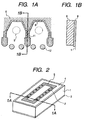
- Figs. 1A and 1B are schematic cross-sectional views showing an ink jet head constituting the first embodiment of the present invention, wherein Figs. 1A and 1B are respectively a horizontal cross-sectional view showing a part in the vicinity of flow paths and a cross-sectional view along a line 1B-1B in Fig. 1A.
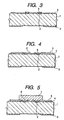
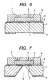
- Figs. 2 to 8 are schematic view showing different stages in a process for producing the ink jet head of the present embodiment, wherein Fig. 2 is a perspective view showing the entire ink jet head while Figs. 3 to 8 are cross-sectional views along a line 1A-1A in Fig. 2.
- the ink jet head of the present embodiment is similar to the conventional ink jet head explained in the foregoing, with respect to the shape and arrangement of an ink supply aperture 10 formed in a substrate 1, a flow path wall 11 formed by a flow path forming member 8 and a ceiling portion including a discharge port 9.
- the substrate 1 is provided in the vicinity of the center thereof with an ink supply aperture 10 having an oblong rectangular planar shape.
- an ink discharge pressure generating element 2 on both sides of the ink supply aperture 10 and along the longitudinal direction thereof.
- an electrothermal converting element consisting of TaN is employed as the ink discharge pressure generating element 2, and the substrate 1 is provided thereon with control signal input electrodes (not shown) for driving the electrothermal converting elements.
- the substrate 1 is further provided thereon with a SiN layer 4 so as to cover the substantially entire surface of the substrate 1 for protecting these elements and electrodes, and also with a Ta layer 5 in a position covering the ink discharge pressure generating element 2.
- the Ta layer 5 is formed continuously between those on the adjacent ink discharge pressure generating elements 2 whereby it is formed in a belt-like shape along the array direction thereof. Also such Ta layers formed in the belt-like shape on both sides of the ink supply aperture 10 are mutually connected at the ends in the array direction of the ink discharge pressure generating elements 2 to constitute an entirely connected Ta layer 5.
- the flow path forming member 8 of epoxy resin forms a flow path wall 11 and thereon a ceiling portion including the discharge port 9. Also there is formed, on the ink supply aperture 10, a common liquid chamber for containing the ink to be supplied to the discharge ports 9.
- the discharge ports 9 are formed above and in opposed relationship to the plural ink discharge pressure generating elements 2 formed on the substrate 1.
- the flow path walls 11 are formed in a comb-tooth shape, thereby forming, between each pair of flow path walls 11, a flow path extending from the common liquid chamber to a position on each discharge pressure generating element 2.
- Such flow path and the discharge port 9 constitute a nozzle.
- the flow path wall 11 is positioned not only on the SiN layer 4 but also on the Ta layer 5.
- the flow path wall 11 At the entrance of each flow path, there are provided vertically extending two pillars 12 with a predetermined gap therebetween for example in order to prevent entry of dusts into the flow path.
- an adhesion layer 6 composed of polyetheramide.
- the pattern of formation of the adhesion layer 6 is different from that in the conventional configuration. More specifically, the adhesion layer 6 is formed in a planar area narrower than the flow path forming member 8 except for the front end portion of the flow path wall 11 formed by the flow path forming member 8, but is formed in a planar area wider than the flow path forming member 8 in the front end portion of the flow path wall 11. More specifically, the flow path wall 11 has a width of about 10 ⁇ m, while the adhesion layer 6 has a width of about 15 ⁇ m in the front end portion of the flow path and about 5 ⁇ m in an interim portion.
- the substrate 1 An Si wafer of crystalline orientation ⁇ 100> was employed as the substrate 1, and the ink supply aperture mask 3 was formed on the lower surface excluding a portion to constitute the ink supply aperture 10. Then the ink discharge pressure generating elements 2 and the control signal input electrodes (not shown) were formed on the upper surface of the substrate 1. Then formed thereon were the SiN layer 4 as a protective layer and the Ta layer 5 as an anticavitation layer. Figs. 2 and 3 schematically show the ink jet head in this stage.
- the polyeitheramide layer with a thickness of 2.0 ⁇ m for constituting the adhesion layer 6.
- the polyetheramide composed of HIMAL1200 (trade name) supplied by Hitachi Chemical Industries Co., was coated on the substrate 1 by a spinner and was baked under heating for 30 minutes at 100°C and then for 1 hour at 250°C.
- positive photoresist ODUR (trade name) supplied by Tokyo Oka Co. was coated on the substrate 1 with a thickness of 12 ⁇ m and was patterned to have a desired flow path pattern thereby obtaining the flow path pattern as shown in Fig. 5.
- the SiN layer 4 was removed in a portion above the ink supply aperture 10, and the flow path pattern 7 was removed by dissolution. Then the epoxy resin layer constituting the flow path forming member 8 was completely hardened by heating for 1 hour at 180°C, whereby the ink jet head as shown in Fig. 8 was obtained.
- the stress in the flow path forming member 8 tends to be concentrated in the front end portion of the flow path wall 11 as explained in the foregoing. Also the stress applied to the flow path forming member by the ink flow tends to be concentrated in the front end portion of the flow path wall 11.
- the adhesion layer 6 is formed in an area wider than the flow path wall 11, at the front end portion thereof where the stress tends to be concentrated.
- the front end portion of the flow path wall 11 has a relatively high adhesion force, whereby the peeling of the flow path forming member 8 can be suppressed even if the stress is concentrated. Furthermore the front end portion of the flow path wall 11 can serve to absorb the stress and to relieve a portion adjoined to the Ta layer 5 of relatively weak adhesion force from excessive stress application, thereby preventing peeling, from the Ta layer 5, of the adhesion layer 6 in a state adjoined to the flow path forming member 8.
- the overflowing portion of the adhesion layer 6 from the flow path wall 11 forms a step difference in the flow path, but such step difference is formed in a root portion of the flow path relatively distant from the discharge port 9 serving to execute the ink discharge, and such overflowing portion is relatively small. Therefore, the presence of such step difference has a relatively small influence on the ink flowability in the flow path and does not affect much the ink discharging characteristics or the ink filling characteristics at the ink filling operation after the ink discharge.
- the present embodiment allows to minimize the peeling between the flow path forming member 8 and the substrate 1 and to maintain the adjoining between the flow path forming member 8 and the substrate 1 in satisfactory condition over a prolonged period. Consequently there can be provided an ink jet head capable of satisfactory recording operation with high reliability even in a prolonged period of use.
- the ink jet head of the present embodiment was prepared, filled with ink and subjected to a storage test for a month under a condition of 60°C. As a result, there were scarcely observed changes such as peeling between the substrate 1 and the flow path forming member 8 or formation of interference fringes on the adhesion face of the flow path forming member 8 resulting from partial peeling.
- Figs. 9A and 9B are schematic cross-sectional views showing an ink jet head constituting the second embodiment of the present invention, and are respectively a horizontal cross-sectional view showing a part in the vicinity of flow paths and a cross-sectional view along a line 9B-9B in Fig. 9A.
- the ink jet head of the present embodiment is similar to that of the first embodiment except for the forming area of the adhesion layer 6, and the like portions of the present embodiment will not therefore be explained further.
- the adhesion layer 6 is formed in an area wider than the flow path wall 11 at the front end portion thereof.
- the adhesion layer 6 is not formed in the intermediate portion of the flow path wall 11, so that the portion of the adhesion layer 6, formed at the front end portion of the flow path wall 11, is independent from other portions.
- Such pattern of the adhesion layer 6 is particularly effective in case the flow path wall 11 has a very narrow width for example in order to secure a wide flow path for obtaining desired ink flowability. In such case, it is difficult to form the adhesion layer 6 narrower than the flow path wall 11, and, even if formed, to expect an effect of increasing the adhesion force. On the other hand, it is easy to form the adhesion layer 6 wider than the flow path wall 11, and it is possible by such adhesion layer 6 to effectively increase the adhesion force at the front end portion of the flow path wall 11.
- the flow path wall 11 has a small adjoining area so that the adjoining force thereof becomes small if without the adhesion layer 6.
- the presence of the adhesion layer 6 wider than the flow path wall 11 at the front end portion thereof where the adjoining force tends to become small allows to effectively increase the adjoining force of the flow path wall 11.
- the stress resulting from the swelling of the flow path forming member 8 or that resulting from the ink flow tend to be concentrated in the front end portion of the flow path wall 11, and the presence of the adhesion layer 6 in a planar area wider than the flow path wall 11 in such portion allows to prevent peeling of the flow path forming member 8.
- the front end portion of the flow path wall 11 absorbs the stress to reduce the stress applied to other adjoining portions of the flow path forming member 8, including the portion adjoined to the Ta layer 5, thereby preventing peeling in such other portions.
- step difference formed by the overflowing of the adhesion layer 6 from the flow path wall 11 is present in the root portion of the flow path and such overflowing portion is small. Consequently the influence on the ink flowability in the flow path is relatively small, and the influence on the ink discharge characteristics or on the ink filling characteristics is also not so large.
- the ink jet head of the present embodiment was prepared, filled with ink and subjected to a storage test for a month under a condition of 60°C. As a result, there were scarcely observed changes such as peeling between the substrate 1 and the flow path forming member 8 or formation of interference fringes on the adhesion face of the flow path forming member 8 resulting from partial peeling.
- Figs. 10A and 10B are schematic cross-sectional views showing an ink jet head constituting the third embodiment of the present invention, and are respectively a horizontal cross-sectional view showing a part in the vicinity of flow paths and a cross-sectional view along a line 10B-10B in Fig. 10A.
- the ink jet head of the present embodiment is similar to that of the first and second embodiments except for the forming area of the adhesion layer 6, and the like portions of the present embodiment will not therefore be explained further.
- the adhesion layer 6 is formed, in the front end portion of the flow path wall 11, in a belt-like shape extending in the direction of array of the plural flow path walls 11.
- Such pattern of the adhesion layer 6 is particularly effective in case the ink discharge pressure generating elements 2 and the discharge ports 9 are formed with a relatively small pitch for example in order to enable pixel formation of a relatively high density, namely in case the flow path walls 11 are formed with a very small pitch. In such case, it may be easier to form the adhesion layer 6 in belt-like shape, rather than to form the adhesion layer 6 independently for each flow path wall 11.
- Such belt-like shaped adhesion layer 6 allows to effectively increase the adhesion force at the front end portion of the flow path wall 11.
- the stress resulting from the swelling of the flow path forming member 8 or that resulting from the ink flow tend to be concentrated in the front end portion of the flow path wall 11, and the presence of the adhesion layer 6 in a planar area wider than the flow path wall 11 in such portion allows to prevent peeling of the flow path forming member 8.
- the front end portion of the flow path wall 11 absorbs the stress to reduce the stress applied to other adjoining portions of the flow path forming member 8, including the portion adjoined to the Ta layer 5, thereby preventing peeling in such other portions.
- step difference formed by the overflowing of the adhesion layer 6 from the flow path wall 11 is present in the root portion of the flow path and such overflowing portion is small. Consequently the influence on the ink flowability in the flow path is relatively small, and the influence on the ink discharge characteristics or on the ink filling characteristics is also not so large.
- the ink jet head of the present embodiment was prepared, filled with ink and subjected to a storage test for a month under a condition of 60°C. As a result, there were scarcely observed changes such as peeling between the substrate 1 and the flow path forming member 8 or formation of interference fringes on the adhesion face of the flow path forming member 8 resulting from partial peeling.
- the adhesion layer 6 is not formed in the planar area where the pillar 12 is formed, so that the pillar 12 is formed on the substrate 1 solely across the SiN layer 4.
- the belt-like shaped adhesion layer 6 formed in the front end portion of the flow path wall 11 passes a part of the formation area of the pillar 12, so that the pillar 12 is partially formed across the adhesion layer 6.
- the pillar 12 is provided for example for preventing dust intrusion into the flow path as explained in the foregoing and need not necessarily be completed adjoined to the substrate 1. Therefore the belt-like shaped adhesion layer 6 may be so formed as to exclude the area of the pillar 12.
- the adhesion layer 6 may be formed in a planar area passing through the forming area of the pillar 12.
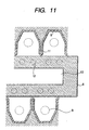
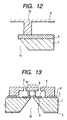
- Figs. 11 to 13 show the ink jet head in such a variation, and are respectively a horizontal cross-sectional view showing a part in the vicinity of the ink supply aperture of such ink jet head, a lateral cross-sectional view of a part in the vicinity of the ink supply aperture, and a lateral cross-sectional view of the entire head.
- the adhesion layer 6 in the vicinity of the pillar 12 is to show the shape of the adhesion layer 6 in the vicinity of the pillar 12 and shows, for the purpose of simplicity, a configuration in which the adhesion layer 6 is formed in an area narrower than the planar area of the flow path wall 11 at the front end portion thereof, but the adhesion layer 6 in such portion may assume the configuration in any of the foregoing first to third embodiments.
- the ink supply aperture 10 is opened in the substrate 1 by a process of forming a through-hole as explained before.
- a membrane consisting of a passivation layer of antietching property is formed on the surface of the substrate 1.
- Such membrane may generate a fissure in any process step for producing the ink jet head such as a step of forming the adhesion layer 6 consisting of polyetheramide on the substrate 1, a step of forming the flow path pattern consisting of the soluble resin, a step of forming the coating resin layer to constitute the flow path forming member, a step of forming discharge port 9 in such coating resin layer in a position above the ink discharge pressure generating element 2 or a step of dissolving out the flow path pattern.
- Such fissure tends to be generated in the vicinity of the end portion of the ink supply aperture 10.
- an adhesion layer 6 for protecting the rim of the ink supply aperture, in such a manner as to slightly overflow in the ink supply aperture 10.
- the presence of such adhesion layer 6 allows to prevent the abnormal fissure in the membrane.
- the pillar 12 is adjoined to thus formed adhesion layer 6 and extends to the ceiling portion.
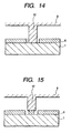
- the pillar 12 needs not necessarily be adjoined to the substrate 1 and the ceiling as explained in the foregoing. Therefore, there may be adopted a configuration shown in Fig. 14, in which the adhesion layer 6 is not formed in the adjoining portion of the pillar 12 to the substrate 1 and in the vicinity thereof, so that the pillar 12 is adjoined to the substrate 1 without across the adhesion layer 6.
- the adhesion layer 6 to be adjoined to the pillar 12 may be formed independently from other portions as shown in Fig. 15.
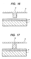
- a configuration in which the pillar 12 is adjoined to and supported by either of the substrate 1 and the ceiling More specifically, there may be adopted a configuration shown in Fig. 16 in which the pillar 12 protrudes from the ceiling portion and does not reach the adhesion layer 6.
- the pillar 12 of such configuration can be obtained by executing two patternings in the step of forming the flow path pattern 7 in the aforementioned process for producing the ink jet head. More specifically, at soluble resin is coated with a thickness corresponding to the gap between the pillar 12 and the adhesion layer 6, and is patterned. In this operation, the resin is not etched in a planar position where the pillar 12 is formed. Then soluble resin is coated with such a thickness for obtaining the desired height of the flow path, including the initial coating thickness. Then the resin is etched in the planar position where the pillar 12 is formed.
- the pillar 12 of the configuration of the present embodiment can be obtained by coating the flow path pattern 7 formed by such two patternings with the resin for constituting the flow path forming member 8.
- pillar 12 extends upwards from the adhesion layer 6 but does not reach the ceiling portion formed by the flow path forming member 8.
- the pillar 12 of such configuration can be formed by the following steps, in the aforementioned process for producing the ink jet head, in coating the flow path pattern 7 with the resin for constituting the flow path forming member 8. At first soluble resin is coated with a thickness corresponding to the height of the pillar 12 and is patterned. In this operation, the resin is etched in the planar position of the pillar 12. Then the resin for constituting the flow path forming member 8 is coated in a recess formed in thus formed flow path pattern 7 corresponding to the forming position of the pillar 12. Then soluble resin is coated with such a thickness for obtaining the desired height of the flow path, including the initial coating thickness. Then the resin is not etched in the planar position where the pillar 12 is formed.
- the pillar 12 of the configuration of the present embodiment can be obtained by coating the flow path pattern 7 with the resin for constituting the flow path forming member 8.
- FIG. 18 is a perspective view schematically showing the configuration of such ink jet recording apparatus.
- the ink jet recording apparatus shown in Fig. 18 is a recording apparatus of serial type, capable of repeating the reciprocating motion (main scanning) of an ink jet head 201 and the conveying (sub scanning) of a recording sheet (recording medium) S such as an ordinary recording paper, a special paper, an OHP film sheet etc. by a predetermined pitch and causing the ink jet head 201 to selectively discharge ink in synchronization with these motions for deposition onto the recording sheet S, thereby forming a character, a symbol or an image.
- a recording sheet (recording medium) S such as an ordinary recording paper, a special paper, an OHP film sheet etc.
- the ink jet head 201 is detachably mounted on a carriage 202 which is slidably supported by two guide rails and is reciprocated along the guide rails by drive means such as an unrepresented motor.
- the recording sheet S is conveyed by a conveying roller 203 in a direction crossing the moving direction of the carriage 202 (for example a perpendicular direction A), so as to be opposed to an ink discharge face of the ink jet head 201 and to maintain a constant distance thereto.
- the recording head 201 is provided with plural nozzle arrays for discharging inks of respectively different colors.
- plural independent main tanks 204 are detachably mounted on an ink supply unit 205.
- the ink supply unit 205 and the recording head 201 are connected by plural ink supply tubes 206 respectively corresponding to the ink colors, and, by mounting the main tanks 204 on the ink supply unit 205, the inks of respective colors contained in the main tanks 204 can be independently supplied to the nozzle arrays in the recording head 201.
- a recovery unit 207 so as to be opposed to the ink discharge face of the recording head 201.
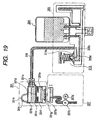
- FIG. 19 is a view showing the ink supply path of the ink jet recording apparatus shown in Fig. 18, showing the path for a color only for the purpose of simplicity.
- Ink is supplied to the recording head 201, from a connector insertion port 201a to which hermetically connected is a liquid connector provided on the end of the ink supply tube 206.
- the connector insertion port 201a communicates with a sub tank 201b formed in the upper part of the recording head 201.
- a liquid chamber 201f for direct ink supply to a nozzle portion having plural nozzles 201g arranged in parallel manner.
- the sub tank 201b and the liquid chamber 201f are separated by a filter 201c, but, at the boundary of the sub tank 201b and the liquid chamber 201f there is formed a partition portion 201d having an aperture 201d, and the filter 201c is provided on such partition portion 201e.
- the ink supplied from the connector insertion port 201a to the recording head 201 is supplied through the sub tank 201b, filter 201c and liquid chamber 201f to the nozzles 201g.
- the path between the connector insertion port 201a to the nozzles 201g is maintained in a hermetically tight condition to the atmosphere.
- the sub tank 201b On the upper face of the sub tank 201b there is formed an aperture which is covered by a dome-shaped elastic member 201h.
- the space surrounded by the elastic member 201h (pressure adjusting chamber 201i) changes volume according to the pressure in the sub tank 201b and has a function of adjusting the pressure in the sub tank 201b.
- the nozzle 201g is positioned with the ink discharging end downwards, and the ink fills the nozzle 201g by forming a meniscus.
- the interior of the recording head 201 particularly the interior of the liquid chamber 201f, is maintained at a negative pressure.
- the ink supply system 205 and the recording head 201 are connected by the ink supply tube 206 and the position of the recording head 201 relative to the ink supply unit 205 can be relatively freely selected, so that the recording head 201 is positioned higher than the ink supply unit 205 in order to maintain the interior of the recording head 201 at a negative pressure.
- the filter 201c is composed of a metal mesh having fine holes smaller than the cross sectional width of the nozzle 201g, in order to prevent leak of a substance that may clog the nozzle 201g, from the sub tank 201b to the liquid chamber 201f.
- the filter 201c has such a property that, when brought into contact with liquid on one surface thereof, each fine hole forms a meniscus of the ink, whereby the ink can easily pass but the air flow through the filter becomes difficult. As the fine hole becomes smaller, the meniscus becomes stronger and the air flow becomes more difficult.
- the liquid chamber 201f is not fully filled with the ink but an air layer is formed between and separates the ink in the liquid chamber 201f and the filter 201c thereby storing the ink of a predetermined amount in the liquid chamber 201f.
- the ink discharge is interrupted at the inversion of the motion of the carriage 202 (cf. Fig. 18) even in a high-duty image formation.
- the pressure adjusting chamber 201i performs a function similar to that of a capacitor, by reducing its volume during the ink discharge operation to relax the increase in the negative pressure in the sub tank 201b and restoring the volume at such inversion of the motion.
- the ink supply needle 205a is provided with a shut-off valve 210 having a rubber diaphragm 210a which is displaced to open or close the connection between the two liquid paths 205c, 205d.
- the shut-off valve 210 is opened during the ink discharge from the recording head 201 but is closed during a standby state or in a non-operated state.
- the configuration of the ink supply unit 205 is provided for each ink color, but the shut-off valves 210 are simultaneously opened or closed for all the ink colors.
- the resulting negative pressure causes the ink to be from time to time supplied from the main tank 204 to the recording head 201 through the ink supply unit 205 and the ink supply tube 206.
- the recovery unit 207 is used for sucking ink and air from the nozzle 201g, and is provided with a suction cap 207a for capping the ink discharge face (face including the aperture of the nozzle 201g) of the recording head 201.
- the suction cap 207a is composed of an elastic member such as of rubber at least in a portion coming into contact with the ink discharge face, and is rendered movable between a position closing the ink discharge face and a position retracted from the recording head 201.
- the suction cap 207a is connected to a tube including therein a suction pump 207c of tube pump type, and is capable of continuous suction by the activation of the suction pump 207c by a pump motor 207d.
- the suction amount can be varied according to the revolution of the pump motor 207d.
- the air permeation through the ink supply tube 206 or the elastic member 201h can be prevented by employing a material of high gas barrier property for these components, but such material is expensive and it is difficult to utilize a high performance material in the mass produced consumer equipment in consideration of the cost.
- the air accumulates gradually by fission of the bubble generated by film boiling of the ink at the ink discharge and returning of such bubble to the liquid chamber 201f, or by gathering of small bubbles, dissolved in the ink, to a large bubble in response to a temperature increase of the ink in the nozzle 201g.
- the air accumulation in the sub tank 201b and the liquid chamber 201f reduces the ink amount therein.
- an ink deficiency causes exposure of the filter 201c to the air, thereby increasing the pressure loss thereof and eventually disabling ink supply to the liquid chamber 201f.
- an ink deficiency in the liquid chamber 201f causes exposure of the upper end of the nozzle 201g to the air, thereby rendering ink supply thereto impossible. In this manner, a fatal situation arises unless each of the sub tank 201b and the liquid chamber 201f contains ink at least equal to a predetermined amount.
- the ink discharging performance can be stably maintained over a long period, even without employing the material of high gas barrier property.
- the ink filling into the sub tank 201b and the liquid chamber 201f is executed utilizing the suction operation by the recovery unit 207. More specifically, the suction pump 207c is activated in a state where the ink discharge face of the recording head 201 is tightly closed by the suction cap 207a, thereby sucking the ink in the recording head 201 from the nozzle 201g.
- ink of an amount approximately equal to the ink sucked from the nozzle 201g flows from the sub tank 201b into the liquid chamber 201f and ink of an amount approximately equal to that flowing out of the sub tank 201b flows from the main tank 204 into the sub tank 201b, so that the situation does not change much from the state prior to suction.
- the sub tank 201b and the liquid chamber 201f separated by the filter 201c respectively with appropriate amounts of ink are reduced to a predetermined pressure utilizing the shut-off valve 210, thereby setting the volumes of the sub tank 201b and the liquid chamber 201f.
- the carriage 202 (cf. Fig. 18) is moved to a position where the recording head 201 is opposed to the suction cap 207a, and the ink discharge face of the recording head 201 is closed by the suction cap 207a. Also the shut-off valve 210 is closed to shut off the ink path from the main tank 204 to the recording head 201.
- the pump motor 207d is activated in this state to execute suction by the suction pump 207c from the suction cap 207a.
- This suction operation sucks ink and air, remaining in the recording head 201, through the nozzle 201g, thereby reducing the pressure in the recording head 201.
- the suction pump 207c is stopped when the suction reaches a predetermined amount. Then the ink discharge face remains in the closed state by the suction cap 207a but the shut-off valve 210 is opened.
- the suction amount of the suction pump 207c is so selected as to bring the interior of the recording head 201 to a predetermined pressure required for filling the sub tank 201b and the liquid chamber 201f with ink of appropriate amounts, and can be determined by calculation or by experiment.
- ink flows into the recording head 201 through the ink supply tube 206, thereby filling each of the sub tank 201b and the liquid chamber 201f with ink.
- the amount of ink filling corresponds to a volume required for returning the sub tank 201b and the liquid chamber 201f to the atmospheric pressure, and is determined by the volume and pressure thereof.
- the ink filling into the sub tank 201b and the liquid chamber 201f is completed in a short time such as about 1 second after opening the shut-off valve 210.
- the suction cap 207a is separated from the recording head 201, and the suction pump 207c is activated again to suck the ink remaining in the suction cap 207a.
- the ink filling operation is completed in this manner.
- the ink filling operation is executed by reducing the pressure in the recording head 201 by the suction pump 207c in a state where the shut-off valve 201 is closed, and then opening the shut-off valve 210.
- the ink is filled within a short time as explained in the foregoing, and a relatively strong ink flow is generated in the recording head 201.
- the ink flow applies a relatively strong stress to the flow path forming member, but the present invention allows to prevent the peeling of the flow path forming member also in such ink filling operation.
- the ink jet recording apparatus in which the ink jet head of the present invention is to mounted is not limited to that explained in the foregoing. There has been explained an ink jet recording apparatus of serial type, but the present invention is likewise applicable to an ink jet recording apparatus of line type, provided with an ink jet head including a nozzle array over the entire width of the recording medium.
Landscapes
- Engineering & Computer Science (AREA)
- Manufacturing & Machinery (AREA)
- Particle Formation And Scattering Control In Inkjet Printers (AREA)
Applications Claiming Priority (2)
| Application Number | Priority Date | Filing Date | Title |
|---|---|---|---|
| JP2001048665 | 2001-02-23 | ||
| JP2001048665A JP3728210B2 (ja) | 2001-02-23 | 2001-02-23 | インクジェットヘッドおよびその製造方法、インクジェット記録装置 |
Publications (2)
| Publication Number | Publication Date |
|---|---|
| EP1234671A1 EP1234671A1 (en) | 2002-08-28 |
| EP1234671B1 true EP1234671B1 (en) | 2005-11-30 |
Family
ID=18909896
Family Applications (1)
| Application Number | Title | Priority Date | Filing Date |
|---|---|---|---|
| EP02003895A Expired - Lifetime EP1234671B1 (en) | 2001-02-23 | 2002-02-21 | Ink jet head, producing method therefor and ink jet recording apparatus |
Country Status (9)
| Country | Link |
|---|---|
| US (1) | US6676241B2 (enExample) |
| EP (1) | EP1234671B1 (enExample) |
| JP (1) | JP3728210B2 (enExample) |
| KR (1) | KR100460244B1 (enExample) |
| CN (1) | CN1189323C (enExample) |
| AT (1) | ATE311294T1 (enExample) |
| AU (1) | AU784872B2 (enExample) |
| CA (1) | CA2372371C (enExample) |
| DE (1) | DE60207622T2 (enExample) |
Families Citing this family (21)
| Publication number | Priority date | Publication date | Assignee | Title |
|---|---|---|---|---|
| JP2004001490A (ja) | 2002-04-23 | 2004-01-08 | Canon Inc | インクジェットヘッド |
| JP3891561B2 (ja) | 2002-07-24 | 2007-03-14 | キヤノン株式会社 | インクジェット記録ヘッド |
| ITTO20020876A1 (it) * | 2002-10-10 | 2004-04-11 | Olivetti I Jet Spa | Dispositivo di stampa a getto di inchiostro in parallelo |
| US7699449B2 (en) * | 2003-06-20 | 2010-04-20 | Seiko Epson Corporation | Liquid injection apparatus and method for driving the same |
| KR100765315B1 (ko) * | 2004-07-23 | 2007-10-09 | 삼성전자주식회사 | 기판과 일체로 이루어진 필터링 부재를 구비하는 잉크젯헤드 및 그 제조방법. |
| JP4241605B2 (ja) * | 2004-12-21 | 2009-03-18 | ソニー株式会社 | 液体吐出ヘッドの製造方法 |
| JP2006297683A (ja) * | 2005-04-19 | 2006-11-02 | Sony Corp | 液体吐出ヘッド及び液体吐出ヘッドの製造方法 |
| JP4656641B2 (ja) * | 2005-06-02 | 2011-03-23 | キヤノン株式会社 | 記録ヘッドおよび記録装置 |
| US7983150B2 (en) * | 2006-01-18 | 2011-07-19 | Corrigent Systems Ltd. | VPLS failure protection in ring networks |
| JP4856982B2 (ja) * | 2006-03-02 | 2012-01-18 | キヤノン株式会社 | インクジェット記録ヘッド |
| US7695111B2 (en) | 2006-03-08 | 2010-04-13 | Canon Kabushiki Kaisha | Liquid discharge head and manufacturing method therefor |
| JP5006663B2 (ja) * | 2006-03-08 | 2012-08-22 | キヤノン株式会社 | 液体吐出ヘッド |
| US7585052B2 (en) * | 2006-07-28 | 2009-09-08 | Hewlett-Packard Development Company, L.P. | Topography layer |
| US7699441B2 (en) * | 2006-12-12 | 2010-04-20 | Eastman Kodak Company | Liquid drop ejector having improved liquid chamber |
| KR20090062012A (ko) * | 2007-12-12 | 2009-06-17 | 삼성전자주식회사 | 잉크젯 헤드 및 그 제조방법 |
| US8435805B2 (en) * | 2010-09-06 | 2013-05-07 | Canon Kabushiki Kaisha | Method of manufacturing a substrate for liquid ejection head |
| JP6083986B2 (ja) * | 2012-04-27 | 2017-02-22 | キヤノン株式会社 | 液体吐出ヘッド |
| WO2014018008A1 (en) * | 2012-07-24 | 2014-01-30 | Hewlett-Packard Company, L.P. | Fluid ejection device with particle tolerant thin-film extension |
| JP6478763B2 (ja) | 2015-03-30 | 2019-03-06 | キヤノン株式会社 | 液体吐出ヘッド |
| US10632747B2 (en) * | 2016-10-14 | 2020-04-28 | Hewlett-Packard Development Company, L.P. | Fluid ejection device |
| JP7091169B2 (ja) * | 2018-07-03 | 2022-06-27 | キヤノン株式会社 | 液体吐出ヘッドとその製造方法 |
Family Cites Families (12)
| Publication number | Priority date | Publication date | Assignee | Title |
|---|---|---|---|---|
| JPH0645242B2 (ja) | 1984-12-28 | 1994-06-15 | キヤノン株式会社 | 液体噴射記録ヘツドの製造方法 |
| EP0317171A3 (en) * | 1987-11-13 | 1990-07-18 | Hewlett-Packard Company | Integral thin film injection system for thermal ink jet heads and methods of operation |
| ES2076217T3 (es) * | 1988-10-31 | 1995-11-01 | Canon Kk | Aparato para la impresion por chorros de liquido. |
| JP2683435B2 (ja) * | 1989-12-14 | 1997-11-26 | キヤノン株式会社 | インクジェットノズル製造用接着剤 |
| JP2697937B2 (ja) | 1989-12-15 | 1998-01-19 | キヤノン株式会社 | 活性エネルギー線硬化性樹脂組成物 |
| US5187500A (en) * | 1990-09-05 | 1993-02-16 | Hewlett-Packard Company | Control of energy to thermal inkjet heating elements |
| US6183067B1 (en) | 1997-01-21 | 2001-02-06 | Agilent Technologies | Inkjet printhead and fabrication method for integrating an actuator and firing chamber |
| US6155674A (en) | 1997-03-04 | 2000-12-05 | Hewlett-Packard Company | Structure to effect adhesion between substrate and ink barrier in ink jet printhead |
| US6045214A (en) * | 1997-03-28 | 2000-04-04 | Lexmark International, Inc. | Ink jet printer nozzle plate having improved flow feature design and method of making nozzle plates |
| JP3184868B2 (ja) | 1997-06-05 | 2001-07-09 | 株式会社日立製作所 | Webページの真正性確認システム |
| US6286939B1 (en) * | 1997-09-26 | 2001-09-11 | Hewlett-Packard Company | Method of treating a metal surface to increase polymer adhesion |
| DE69923033T2 (de) * | 1998-06-03 | 2005-12-01 | Canon K.K. | Tintenstrahlkopf, Tintenstrahlkopfträgerschicht, und Verfahren zur Herstellung des Kopfes |
-
2001
- 2001-02-23 JP JP2001048665A patent/JP3728210B2/ja not_active Expired - Fee Related
-
2002
- 2002-02-20 US US10/077,799 patent/US6676241B2/en not_active Expired - Lifetime
- 2002-02-20 CA CA002372371A patent/CA2372371C/en not_active Expired - Fee Related
- 2002-02-21 EP EP02003895A patent/EP1234671B1/en not_active Expired - Lifetime
- 2002-02-21 AU AU16816/02A patent/AU784872B2/en not_active Ceased
- 2002-02-21 DE DE60207622T patent/DE60207622T2/de not_active Expired - Lifetime
- 2002-02-21 AT AT02003895T patent/ATE311294T1/de not_active IP Right Cessation
- 2002-02-22 CN CNB021233322A patent/CN1189323C/zh not_active Expired - Fee Related
- 2002-02-23 KR KR10-2002-0009695A patent/KR100460244B1/ko not_active Expired - Fee Related
Also Published As
| Publication number | Publication date |
|---|---|
| DE60207622T2 (de) | 2006-07-20 |
| CA2372371C (en) | 2006-01-03 |
| US20020122101A1 (en) | 2002-09-05 |
| EP1234671A1 (en) | 2002-08-28 |
| KR20020069172A (ko) | 2002-08-29 |
| US6676241B2 (en) | 2004-01-13 |
| AU784872B2 (en) | 2006-07-13 |
| JP3728210B2 (ja) | 2005-12-21 |
| AU1681602A (en) | 2002-08-29 |
| DE60207622D1 (de) | 2006-01-05 |
| JP2002248771A (ja) | 2002-09-03 |
| CN1189323C (zh) | 2005-02-16 |
| CA2372371A1 (en) | 2002-08-23 |
| CN1383985A (zh) | 2002-12-11 |
| ATE311294T1 (de) | 2005-12-15 |
| KR100460244B1 (ko) | 2004-12-08 |
Similar Documents
| Publication | Publication Date | Title |
|---|---|---|
| EP1234671B1 (en) | Ink jet head, producing method therefor and ink jet recording apparatus | |
| US6520626B1 (en) | Liquid ejection head, method for preventing accidental non-eject using the ejection head and manufacturing method of the ejection head | |
| US6213590B1 (en) | Inkjet head for reducing pressure interference between ink supply passages | |
| EP0500068B1 (en) | Ink jet recording head, recording apparatus using same and method for manufacturing same | |
| AU784532B2 (en) | Liquid supply system, ink jet recording head, ink jet recording apparatus and liquid filling method | |
| CN1191167C (zh) | 制造单体喷墨打印头的方法 | |
| EP0921001B1 (en) | Thermal ink jet printhead with fluid flow resisting member in channel | |
| US6505915B2 (en) | Liquid ejection head, apparatus and recovery method for them | |
| JP2007203623A (ja) | インクジェット記録ヘッド及びその製造方法 | |
| US20240359460A1 (en) | Liquid ejection head and method for manufacturing the same | |
| US6371598B1 (en) | Ink jet recording apparatus, and an ink jet head | |
| JP2008179039A (ja) | 液体吐出ヘッド及び液体吐出ヘッドの製造方法 | |
| JPH0577423A (ja) | インクジエツト記録ヘツド | |
| JP2007144878A (ja) | インクジェット記録ヘッド用基板、インクジェット記録ヘッドおよびインクジェット記録ヘッド用基板の製造方法 | |
| JP6128982B2 (ja) | 液体吐出ヘッド | |
| JPH05338168A (ja) | インクジェット記録ヘッド | |
| US10406813B2 (en) | Liquid ejection head | |
| JP2004284277A (ja) | インクジェット記録ヘッド、インクジェット記録装置及びインクジェット記録ヘッドへのインク供給方法 | |
| JP2006082331A (ja) | インクジェット記録ヘッドの製造方法 | |
| JP2001063068A (ja) | インクジェットヘッド及びその製造方法 | |
| AU9817798A (en) | Liquid ejection head, apparatus and recovery method for them |
Legal Events
| Date | Code | Title | Description |
|---|---|---|---|
| PUAI | Public reference made under article 153(3) epc to a published international application that has entered the european phase |
Free format text: ORIGINAL CODE: 0009012 |
|
| AK | Designated contracting states |
Kind code of ref document: A1 Designated state(s): AT BE CH CY DE DK ES FI FR GB GR IE IT LI LU MC NL PT SE TR |
|
| AX | Request for extension of the european patent |
Free format text: AL;LT;LV;MK;RO;SI |
|
| 17P | Request for examination filed |
Effective date: 20030114 |
|
| 17Q | First examination report despatched |
Effective date: 20030328 |
|
| AKX | Designation fees paid |
Designated state(s): AT BE CH CY DE DK ES FI FR GB GR IE IT LI LU MC NL PT SE TR |
|
| GRAP | Despatch of communication of intention to grant a patent |
Free format text: ORIGINAL CODE: EPIDOSNIGR1 |
|
| GRAS | Grant fee paid |
Free format text: ORIGINAL CODE: EPIDOSNIGR3 |
|
| GRAA | (expected) grant |
Free format text: ORIGINAL CODE: 0009210 |
|
| AK | Designated contracting states |
Kind code of ref document: B1 Designated state(s): AT BE CH CY DE DK ES FI FR GB GR IE IT LI LU MC NL PT SE TR |
|
| PG25 | Lapsed in a contracting state [announced via postgrant information from national office to epo] |
Ref country code: CH Free format text: LAPSE BECAUSE OF FAILURE TO SUBMIT A TRANSLATION OF THE DESCRIPTION OR TO PAY THE FEE WITHIN THE PRESCRIBED TIME-LIMIT Effective date: 20051130 Ref country code: BE Free format text: LAPSE BECAUSE OF FAILURE TO SUBMIT A TRANSLATION OF THE DESCRIPTION OR TO PAY THE FEE WITHIN THE PRESCRIBED TIME-LIMIT Effective date: 20051130 Ref country code: FI Free format text: LAPSE BECAUSE OF FAILURE TO SUBMIT A TRANSLATION OF THE DESCRIPTION OR TO PAY THE FEE WITHIN THE PRESCRIBED TIME-LIMIT Effective date: 20051130 Ref country code: LI Free format text: LAPSE BECAUSE OF FAILURE TO SUBMIT A TRANSLATION OF THE DESCRIPTION OR TO PAY THE FEE WITHIN THE PRESCRIBED TIME-LIMIT Effective date: 20051130 Ref country code: NL Free format text: LAPSE BECAUSE OF FAILURE TO SUBMIT A TRANSLATION OF THE DESCRIPTION OR TO PAY THE FEE WITHIN THE PRESCRIBED TIME-LIMIT Effective date: 20051130 Ref country code: AT Free format text: LAPSE BECAUSE OF FAILURE TO SUBMIT A TRANSLATION OF THE DESCRIPTION OR TO PAY THE FEE WITHIN THE PRESCRIBED TIME-LIMIT Effective date: 20051130 |
|
| REG | Reference to a national code |
Ref country code: GB Ref legal event code: FG4D Ref country code: CH Ref legal event code: EP |
|
| REG | Reference to a national code |
Ref country code: IE Ref legal event code: FG4D |
|
| REF | Corresponds to: |
Ref document number: 60207622 Country of ref document: DE Date of ref document: 20060105 Kind code of ref document: P |
|
| PG25 | Lapsed in a contracting state [announced via postgrant information from national office to epo] |
Ref country code: IE Free format text: LAPSE BECAUSE OF NON-PAYMENT OF DUE FEES Effective date: 20060221 |
|
| PG25 | Lapsed in a contracting state [announced via postgrant information from national office to epo] |
Ref country code: SE Free format text: LAPSE BECAUSE OF FAILURE TO SUBMIT A TRANSLATION OF THE DESCRIPTION OR TO PAY THE FEE WITHIN THE PRESCRIBED TIME-LIMIT Effective date: 20060228 Ref country code: DK Free format text: LAPSE BECAUSE OF FAILURE TO SUBMIT A TRANSLATION OF THE DESCRIPTION OR TO PAY THE FEE WITHIN THE PRESCRIBED TIME-LIMIT Effective date: 20060228 Ref country code: LU Free format text: LAPSE BECAUSE OF NON-PAYMENT OF DUE FEES Effective date: 20060228 Ref country code: GR Free format text: LAPSE BECAUSE OF FAILURE TO SUBMIT A TRANSLATION OF THE DESCRIPTION OR TO PAY THE FEE WITHIN THE PRESCRIBED TIME-LIMIT Effective date: 20060228 Ref country code: MC Free format text: LAPSE BECAUSE OF NON-PAYMENT OF DUE FEES Effective date: 20060228 |
|
| PG25 | Lapsed in a contracting state [announced via postgrant information from national office to epo] |
Ref country code: ES Free format text: LAPSE BECAUSE OF FAILURE TO SUBMIT A TRANSLATION OF THE DESCRIPTION OR TO PAY THE FEE WITHIN THE PRESCRIBED TIME-LIMIT Effective date: 20060313 |
|
| PG25 | Lapsed in a contracting state [announced via postgrant information from national office to epo] |
Ref country code: PT Free format text: LAPSE BECAUSE OF FAILURE TO SUBMIT A TRANSLATION OF THE DESCRIPTION OR TO PAY THE FEE WITHIN THE PRESCRIBED TIME-LIMIT Effective date: 20060502 |
|
| NLV1 | Nl: lapsed or annulled due to failure to fulfill the requirements of art. 29p and 29m of the patents act | ||
| REG | Reference to a national code |
Ref country code: CH Ref legal event code: PL |
|
| ET | Fr: translation filed | ||
| PLBE | No opposition filed within time limit |
Free format text: ORIGINAL CODE: 0009261 |
|
| STAA | Information on the status of an ep patent application or granted ep patent |
Free format text: STATUS: NO OPPOSITION FILED WITHIN TIME LIMIT |
|
| 26N | No opposition filed |
Effective date: 20060831 |
|
| REG | Reference to a national code |
Ref country code: IE Ref legal event code: MM4A |
|
| PG25 | Lapsed in a contracting state [announced via postgrant information from national office to epo] |
Ref country code: TR Free format text: LAPSE BECAUSE OF FAILURE TO SUBMIT A TRANSLATION OF THE DESCRIPTION OR TO PAY THE FEE WITHIN THE PRESCRIBED TIME-LIMIT Effective date: 20051130 |
|
| PG25 | Lapsed in a contracting state [announced via postgrant information from national office to epo] |
Ref country code: CY Free format text: LAPSE BECAUSE OF FAILURE TO SUBMIT A TRANSLATION OF THE DESCRIPTION OR TO PAY THE FEE WITHIN THE PRESCRIBED TIME-LIMIT Effective date: 20051130 |
|
| PG25 | Lapsed in a contracting state [announced via postgrant information from national office to epo] |
Ref country code: IT Free format text: LAPSE BECAUSE OF NON-PAYMENT OF DUE FEES Effective date: 20080221 |
|
| REG | Reference to a national code |
Ref country code: FR Ref legal event code: PLFP Year of fee payment: 14 |
|
| PGFP | Annual fee paid to national office [announced via postgrant information from national office to epo] |
Ref country code: IT Payment date: 20150206 Year of fee payment: 14 |
|
| PGFP | Annual fee paid to national office [announced via postgrant information from national office to epo] |
Ref country code: FR Payment date: 20150227 Year of fee payment: 14 |
|
| REG | Reference to a national code |
Ref country code: FR Ref legal event code: ST Effective date: 20161028 |
|
| PG25 | Lapsed in a contracting state [announced via postgrant information from national office to epo] |
Ref country code: IT Free format text: LAPSE BECAUSE OF NON-PAYMENT OF DUE FEES Effective date: 20160221 |
|
| PG25 | Lapsed in a contracting state [announced via postgrant information from national office to epo] |
Ref country code: FR Free format text: LAPSE BECAUSE OF NON-PAYMENT OF DUE FEES Effective date: 20160229 |
|
| PGFP | Annual fee paid to national office [announced via postgrant information from national office to epo] |
Ref country code: DE Payment date: 20170228 Year of fee payment: 16 |
|
| PGFP | Annual fee paid to national office [announced via postgrant information from national office to epo] |
Ref country code: GB Payment date: 20170227 Year of fee payment: 16 |
|
| REG | Reference to a national code |
Ref country code: DE Ref legal event code: R119 Ref document number: 60207622 Country of ref document: DE |
|
| GBPC | Gb: european patent ceased through non-payment of renewal fee |
Effective date: 20180221 |
|
| PG25 | Lapsed in a contracting state [announced via postgrant information from national office to epo] |
Ref country code: DE Free format text: LAPSE BECAUSE OF NON-PAYMENT OF DUE FEES Effective date: 20180901 |
|
| PG25 | Lapsed in a contracting state [announced via postgrant information from national office to epo] |
Ref country code: GB Free format text: LAPSE BECAUSE OF NON-PAYMENT OF DUE FEES Effective date: 20180221 |