EP1233205A2 - Disposition de ressort - Google Patents
Disposition de ressort Download PDFInfo
- Publication number
- EP1233205A2 EP1233205A2 EP02002321A EP02002321A EP1233205A2 EP 1233205 A2 EP1233205 A2 EP 1233205A2 EP 02002321 A EP02002321 A EP 02002321A EP 02002321 A EP02002321 A EP 02002321A EP 1233205 A2 EP1233205 A2 EP 1233205A2
- Authority
- EP
- European Patent Office
- Prior art keywords
- spring
- suspension
- arrangement according
- suspension arrangement
- base
- Prior art date
- Legal status (The legal status is an assumption and is not a legal conclusion. Google has not performed a legal analysis and makes no representation as to the accuracy of the status listed.)
- Granted
Links
Images


Classifications
-
- F—MECHANICAL ENGINEERING; LIGHTING; HEATING; WEAPONS; BLASTING
- F16—ENGINEERING ELEMENTS AND UNITS; GENERAL MEASURES FOR PRODUCING AND MAINTAINING EFFECTIVE FUNCTIONING OF MACHINES OR INSTALLATIONS; THERMAL INSULATION IN GENERAL
- F16F—SPRINGS; SHOCK-ABSORBERS; MEANS FOR DAMPING VIBRATION
- F16F1/00—Springs
- F16F1/02—Springs made of steel or other material having low internal friction; Wound, torsion, leaf, cup, ring or the like springs, the material of the spring not being relevant
- F16F1/04—Wound springs
- F16F1/12—Attachments or mountings
- F16F1/128—Attachments or mountings with motion-limiting means, e.g. with a full-length guide element or ball joint connections; with protective outer cover
-
- B—PERFORMING OPERATIONS; TRANSPORTING
- B60—VEHICLES IN GENERAL
- B60G—VEHICLE SUSPENSION ARRANGEMENTS
- B60G11/00—Resilient suspensions characterised by arrangement, location or kind of springs
- B60G11/14—Resilient suspensions characterised by arrangement, location or kind of springs having helical, spiral or coil springs only
- B60G11/16—Resilient suspensions characterised by arrangement, location or kind of springs having helical, spiral or coil springs only characterised by means specially adapted for attaching the spring to axle or sprung part of the vehicle
-
- B—PERFORMING OPERATIONS; TRANSPORTING
- B60—VEHICLES IN GENERAL
- B60G—VEHICLE SUSPENSION ARRANGEMENTS
- B60G11/00—Resilient suspensions characterised by arrangement, location or kind of springs
- B60G11/32—Resilient suspensions characterised by arrangement, location or kind of springs having springs of different kinds
- B60G11/48—Resilient suspensions characterised by arrangement, location or kind of springs having springs of different kinds not including leaf springs
- B60G11/52—Resilient suspensions characterised by arrangement, location or kind of springs having springs of different kinds not including leaf springs having helical, spiral or coil springs, and also rubber springs
- B60G11/54—Resilient suspensions characterised by arrangement, location or kind of springs having springs of different kinds not including leaf springs having helical, spiral or coil springs, and also rubber springs with rubber springs arranged within helical, spiral or coil springs
-
- F—MECHANICAL ENGINEERING; LIGHTING; HEATING; WEAPONS; BLASTING
- F16—ENGINEERING ELEMENTS AND UNITS; GENERAL MEASURES FOR PRODUCING AND MAINTAINING EFFECTIVE FUNCTIONING OF MACHINES OR INSTALLATIONS; THERMAL INSULATION IN GENERAL
- F16F—SPRINGS; SHOCK-ABSORBERS; MEANS FOR DAMPING VIBRATION
- F16F9/00—Springs, vibration-dampers, shock-absorbers, or similarly-constructed movement-dampers using a fluid or the equivalent as damping medium
- F16F9/32—Details
- F16F9/58—Stroke limiting stops, e.g. arranged on the piston rod outside the cylinder
-
- B—PERFORMING OPERATIONS; TRANSPORTING
- B60—VEHICLES IN GENERAL
- B60G—VEHICLE SUSPENSION ARRANGEMENTS
- B60G2202/00—Indexing codes relating to the type of spring, damper or actuator
- B60G2202/10—Type of spring
- B60G2202/12—Wound spring
-
- B—PERFORMING OPERATIONS; TRANSPORTING
- B60—VEHICLES IN GENERAL
- B60G—VEHICLE SUSPENSION ARRANGEMENTS
- B60G2202/00—Indexing codes relating to the type of spring, damper or actuator
- B60G2202/10—Type of spring
- B60G2202/14—Plastic spring, e.g. rubber
- B60G2202/143—Plastic spring, e.g. rubber subjected to compression
-
- B—PERFORMING OPERATIONS; TRANSPORTING
- B60—VEHICLES IN GENERAL
- B60G—VEHICLE SUSPENSION ARRANGEMENTS
- B60G2204/00—Indexing codes related to suspensions per se or to auxiliary parts
- B60G2204/10—Mounting of suspension elements
- B60G2204/12—Mounting of springs or dampers
- B60G2204/124—Mounting of coil springs
-
- B—PERFORMING OPERATIONS; TRANSPORTING
- B60—VEHICLES IN GENERAL
- B60G—VEHICLE SUSPENSION ARRANGEMENTS
- B60G2204/00—Indexing codes related to suspensions per se or to auxiliary parts
- B60G2204/10—Mounting of suspension elements
- B60G2204/12—Mounting of springs or dampers
- B60G2204/128—Damper mount on vehicle body or chassis
-
- B—PERFORMING OPERATIONS; TRANSPORTING
- B60—VEHICLES IN GENERAL
- B60G—VEHICLE SUSPENSION ARRANGEMENTS
- B60G2204/00—Indexing codes related to suspensions per se or to auxiliary parts
- B60G2204/40—Auxiliary suspension parts; Adjustment of suspensions
- B60G2204/45—Stops limiting travel
- B60G2204/4502—Stops limiting travel using resilient buffer
Definitions
- the invention relates to a suspension arrangement with a helical compression spring trained suspension spring according to the features in the preamble of claim 1.
- the suspension in a chassis of a motor vehicle is used for elastic Connection between the body and the wheel guide parts.
- the suspension should the vehicle body from higher frequency wheel vibrations isolate, but at the same time follow the long-wave road contour.
- Next Leaf springs that are mainly used in trucks Torsion bar springs, air springs and silent blocks are known. Come very often Helical compression springs are used, in which are different Wire thicknesses and various forms a progressive, degressive or linear spring detection can be achieved. Have proven to be particularly space-saving thereby barrel springs have been proven, in which the turns when deflecting put into each other.
- additional springs can be used as tension or Pressure stop in parallel with a suspension spring a progressive Enable characteristic curve.
- the usual materials for additional springs are rubber or cellular polyurethane elastomers.
- the additional spring may have at the same time also the function of a stop buffer to avoid a sudden Avoid blocking a helical compression spring.
- the additional springs are arranged outside the suspension spring and in one Holding pot held.
- the additional spring held in a receptacle coaxial with Support spring to be arranged arise in terms of assembly certain difficulties, since there are three different components in a small space must be placed.
- the holder with the additional spring the is to be attached to the spring plate, secondly between the spring plate and Support spring to be arranged spring pad and third the actual one Suspension spring.
- the additional spring with the pot still one pre-assembled unit forms the suspension spring and the spring pad Individual parts that are only oriented in the spring-loaded installation situation. In assembly, the handling of the individual parts is not optimal, especially you Weight is not insignificant.
- the object of the invention is based on the prior art based on creating a suspension arrangement, on the one hand in the Assembly is easy to handle and on the other hand easier Materials can be used.
- the invention solves the problem with in the characterizing part of Claim 1 specified features.
- the essence of the invention is the fact that the spring pad penetrating receptacle and / or stop base a radial has outwardly extending support ring.
- the support ring engages behind the Spring pad on the side facing away from the suspension spring, whereby the Holder with the additional spring and the spring pad or the Stop base and the spring pad form a preassembled unit.
- the advantages of the suspension arrangement according to the invention come especially to wear when the suspension spring is a Barrel spring with a winding diameter that decreases at the end is.
- the outer diameter of the support ring only needs to be slightly larger than the winding diameter of the ends To ensure a secure clamping of the spring pad between the To ensure suspension spring and the support ring.
- For support rings with little Outside diameter is also saved material and thus weight, which ultimately helps to reduce fuel consumption.
- the spring pad one on the receptacle or the stop base radially on the outside adjacent and pointing to the suspension spring, which together with the Stop base or the suspension spring the respective end of the suspension spring in radial direction oriented.
- the pot thus has multiple Functions.
- the suspension spring is supported indirectly via the spring pad against the support ring of the receptacle, the receptacle at the same time one end of the suspension spring in the radial direction position-oriented.
- Central mandrels or the like, as in Barrel springs are not used in this arrangement required.
- the collar pointing to the suspension spring has the function, abrasion and Noise development between the suspension spring and the receptacle avoid.
- the height of the collar suitably corresponds at least the wire diameter of the end turn.
- the stop base in also has functionality like the holder Interaction with the second spring pad. The stop base also serves to position the suspension spring.
- the collar has a radially inward undercut into which engages end winding of the suspension spring.
- the spring force of the Suspension spring snaps the end turn into the undercut on.
- the undercut can be positioned so that the spring pad is supported by the suspension spring additionally in the axial direction against the support ring of the receptacle is pressed.
- Wheel guide parts such as Vehicle axles can have several degrees of freedom have. It is therefore not always guaranteed that when hitting the additional spring on the stop surface of the stop base Central longitudinal axes are congruent, i.e. that the end faces of the Additional spring and the stop base parallel to each other to the system reach. This fact is borne by the features of claim 6 Bill, according to which the stop base facing the additional spring Has stop surface, the surface normal of the central longitudinal axis the suspension spring deviates. When the suspension spring is in its relaxed state The central longitudinal axis is congruent with the additional spring.
- stop surface facing end face of the additional spring with a corresponding To be provided with an incline in order to meet the parallel as possible To ensure additional spring and the stop surface.
- the stop surface of the stop base can be curved concavely be (claim 7), which in particular with additional springs made of rubber or Polyurethane elastomers are advantageous because they are complementary Centering on the surface normal of the stop surface is achieved.
- stop plinths are provided for the receptacle and / or the stop base can be made of plastic (claim 8), whereby a significant weight saving is possible.
- the stop base one engaging in an opening of the body or the wheel guide part Fixing pin on.
- a fixing pin expediently engages as free of play as possible in the opening to ensure proper guidance of the To ensure stop base and thus the suspension spring.
- the stop base should at least according to the features of claim 10 have a clamping web on its outer circumference so that it is firmly in the Opening is kept. Especially when manufacturing the stop base a softer compared to the wheel guide part or the body Material, such as plastic, the clamping webs can Insert into the opening and rub a tight fit of the locating pin and thus ensure the stop base in the opening.
- the Fixing pin in addition to the clamping bars, but above all alternatively, the Fixing pin according to the features of claim 11 several resilient Have clamp hooks with a radially outwardly directed nose, which the Reach behind the edges of the opening.
- the noses preferably have one Inclined surface over which the clamping hooks are mounted in the opening slide. In the snap-in position, those under spring force snap Clamping hooks behind the edges of the opening facing away from the suspension spring, whereby the stop base on the body or the wheel guide part is clipped on.
- the opening has a circular cross section
- the correct installation of the stop base may be possible align its stop surface according to the installation situation. It is therefore provided according to claim 12, the stop base against rotation to store.
- the fixing pin on its outer circumference Alignment web have, which in a corresponding edge Recess of the opening engages. It goes without saying that reverse case conceivable, i.e. that on the outer circumference of the fixing pin Recess is provided with a corresponding projection on Edge of the opening corresponds.
- Anti-twist devices conceivable by a certain shape of the opening are determined, i.e. Openings in which only a positioning of the Stop base is possible.
- anti-rotation locks are also possible outside the opening,
- a pin arranged on the support ring which in a additional hole on the wheel guide part or the body engages.
- the Fixing pin can be designed as a hollow pin.
- the diameter of the fixing pin can vary from the outside diameter of the stop base differ, the diameter difference is bridged over a variety of stiffening ribs.
- An additional Weight can also be saved through a recess on the Reach side of the receptacle facing away from the spring.
- Weight can also be saved by a spring pad on your Has a lattice structure in some areas facing away from the suspension spring (Claim 13). Due to the varying design of the lattice structure the spring identification of the suspension arrangement can also be influenced. Possible parameters are the number, arrangement and geometric Design of the depressions within the lattice structure and the chosen material.
- the spring pad has a space for the support ring offering recess, the lattice structure described above expediently from the outer edge of the support ring to the outer edge of the Spring pad extends.
- the suspension spring has an inconsistent wire diameter.
- the wire diameter preferably decreases towards the ends.
- the spring characteristic of the suspension arrangement by the Configuration of the additional spring can be influenced.
- An additional spring Solid material especially made of rubber or a polyurethane elastomer rather brings with it a steep spring characteristic, whereby the spring characteristic by a material-saving design, in particular by a can set substantially cylindrical hollow spring flatter.
- the additional spring can be barrel-shaped or cylindrical in cross-section, as also have a conical shape, depending on the specific design the desired suspension properties. Here also plays Height and diameter of the pot or the ratio of both parameters matter.
- the receptacle can have one or more circumferential reinforcing grooves have and preferably has an outward side pointing edge, the damage preferably from a Prevents existing elastomeric spring at oblique compression.
- Figure 1 shows a suspension arrangement with a helical compression spring trained suspension spring 1 with inconsistent wire diameter D and itself to their ends 2, 3 reducing winding diameter D1.
- the suspension spring 1 is partially compressed, with their Lay the end turns in a spiral.
- the upper end 2 of the suspension spring 1 in the plane of the drawing is indirectly supported via an annular disk-shaped spring pad 4 on a spring plate 5, to a body of a motor vehicle, not shown heard.
- the other end 3 of the suspension spring 1 engages indirectly over one Spring pad 6 on a wheel guide part shown only in sections 7 indirectly.
- a also coaxial to the central longitudinal axis MLA Support spring 1 aligned stop base 10 is located on the other End 3 of the suspension spring 1.
- Both the receptacle 8 and the stop base 10 enforce the assigned spring pads 4, 6 and reach behind them by one each radially outwardly extending support ring 11, 12, the width B the support rings 11, 12 is smaller than half the width B1 of the annular disc Spring pads 4, 6.
- the spring 1 facing away Pages 13 of the spring pads 4, 6 have corresponding annular Recesses 14 for receiving the support rings 11, 12 so that they and the side facing away from the suspension spring 13 of the spring pads 4, 6 parallel to the Spring plate 5 or the wheel guide part 7 abut.
- One spring pad 4 is centered on a shaft section 15 of the Receptacle 8 passes through, the spring pad 4 a radially the shaft section 15 of the receptacle 8 adjacent and Suspension spring 1 has collar 16.
- the collar 16 is at least so high as the last turn 17 of the suspension spring 1 is thick.
- the winding 17 lies in this way close to the collar 16 that this is pressed together and against the Shank section 15 of the receptacle 8 is pressed.
- the flexible collar 16 a radially inward Have an undercut into which the end turn 17 of the suspension spring 1 intervenes. Due to the clamping effect of the end turn 17 form the Suspension spring 1 and the receptacle 8 with the additional spring 9 and Spring pad 4 is a pre-assembled unit, which as a whole on the Spring plate 5 of the body can be attached.
- the receptacle 8 is in the range of Shaft section 15 with on its side facing away from the additional spring 9 a recess 19, in which in this embodiment Centering dome 20 of the spring plate 5 engages.
- the additional spring 9 is in a itself on the shaft portion 15 of the receptacle 8 subsequent cup-shaped holding section 21 lying on the inside fixed, the holding portion 21 on the mouth side facing outward has facing edge 22.
- the additional spring 9 is made of rubber or a Polyurethane elastomer and is configured with a substantially cylindrical shape spaced apart outer ring notches. in principle the additional spring 9 can also consist of other materials.
- the additional spring 9 should be as vertical as possible when the suspension spring 1 is deflected meet a stop surface 23 of the stop base 10.
- the stop surface 23 is concave curved, their central surface normal FN at an angle W to Central longitudinal axis MLA of the suspension spring 1 in the relaxed state or as in FIG. 1 shown, prestressed state.
- the angle W between the The central longitudinal axis MLA of the suspension spring 1 and the surface normal FN are determined according to the respective installation situation and the kinematics of the axis in the Motor vehicle and enables the suspension arrangement to deflect obliquely an as perpendicular as possible impact of the additional spring 9 on the Stop base 10.
- the stop base 10 has on its surface facing away from the stop surface 23 Side a fixing pin 24 which in an opening 25 in the wheel guide part 7th engages and so the stop base 10 oriented.
- the fixing pin 24 is longitudinally channeled in the direction of the central longitudinal axis MLA of the suspension spring 1, wherein the central longitudinal channel 26 of the fixing pin 24 into the stop surface 23 empties.
- the fixing pin 24 is concentric with a radial distance arranged substantially cylindrical shell portion 27, the Sheath section 27 carries the support ring 12 at one end and on the other end is limited by the stop surface 23.
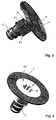
- Figure 2 shows the suspension arrangement shown in Figure 1 in perspective Representation without the spring plate 5 shown in Figure 1 and that Wheel guide part 7.
- This rear view of the suspension spring 1 opposite side 13 of the spring pad 4 is its grid-like configuration recognizable with evenly spaced radial webs 28 and concentric Rings 29.
- the spacing of the radial webs 28 and the rings 29 determines the spring identification of the spring pad 4 and the possible Weight saving of this component.
- the spring pad 6 on the stop base 10 also has a lattice structure, like the cross-sectional representation 1 shows.
- Figures 3 and 4 show two possible embodiments of a Receptacle with spring base 4, the one shown in Figure 3 Receptacle 8a made of steel or an aluminum alloy consists of a additional inward indentation 30 on its outer circumference 31, which serves as stiffening of the receptacle 8a.
- the receptacle 8b consists of Plastic and differs in this respect from the execution of the Receptacle 8a made of steel or aluminum materials that in the area the recess 19 on the side facing away from the suspension spring 1 radially inside stiffening ribs 32 are attached.
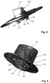
- the stop base 10a shown in Figure 5 is with a clip mechanism held in the opening 25 of the wheel guide part 7. For this are several on the circumference of the fixing pin, which is no longer visible distributed resilient clamp hooks 33 placed with radially outward directed Lugs 34 that snap behind the edges 35 of the opening 25.
- the noses 34 each have an obliquely outward sloping surface 36 that the Introducing the stop base 10 into the opening 25 facilitates.
- FIG Figure 6 A further possibility for fastening a stop base 10b is shown in FIG Figure 6 shown.
- plastic Stop base 10b axially extending clamping webs 37 on the outer circumference 38 of a fixing pin 39 placed.
- the height of the clamping webs 37 is so dimensioned that this when inserting the stop base 10b in rub an opening to a certain extent and a clamping of the Secure the fixing pin 39 in the opening.
- the Clamping webs 37 have a fixing pin 39 which is also axially oriented extending alignment web 40 with which the angular position of the stop base 10b can be set in the opening.
- the alignment bridge 40 is cone-shaped in this embodiment with a round cross section trained and intervenes in the installation situation in a suitably configured Recess in the opening. 6 continues to be radial aligned stiffening ribs 41 clearly used to stiffen the Stop base 10b serve.
- the stiffening ribs 41 extend in the Height range of the jacket section 42 starting from this in the direction on the fixing pin
Landscapes
- Engineering & Computer Science (AREA)
- Mechanical Engineering (AREA)
- General Engineering & Computer Science (AREA)
- Springs (AREA)
- Vehicle Body Suspensions (AREA)
- Transition And Organic Metals Composition Catalysts For Addition Polymerization (AREA)
- Input Circuits Of Receivers And Coupling Of Receivers And Audio Equipment (AREA)
Applications Claiming Priority (2)
| Application Number | Priority Date | Filing Date | Title |
|---|---|---|---|
| DE10106915A DE10106915C2 (de) | 2001-02-15 | 2001-02-15 | Federungsanordnung |
| DE10106915 | 2001-02-15 |
Publications (3)
| Publication Number | Publication Date |
|---|---|
| EP1233205A2 true EP1233205A2 (fr) | 2002-08-21 |
| EP1233205A3 EP1233205A3 (fr) | 2003-12-03 |
| EP1233205B1 EP1233205B1 (fr) | 2004-12-22 |
Family
ID=7674054
Family Applications (1)
| Application Number | Title | Priority Date | Filing Date |
|---|---|---|---|
| EP02002321A Expired - Lifetime EP1233205B1 (fr) | 2001-02-15 | 2002-01-31 | Disposition de ressort |
Country Status (6)
| Country | Link |
|---|---|
| US (1) | US6733023B2 (fr) |
| EP (1) | EP1233205B1 (fr) |
| AT (1) | ATE285534T1 (fr) |
| CZ (1) | CZ299507B6 (fr) |
| DE (2) | DE10106915C2 (fr) |
| ES (1) | ES2233722T3 (fr) |
Cited By (1)
| Publication number | Priority date | Publication date | Assignee | Title |
|---|---|---|---|---|
| DE102004010823A1 (de) * | 2004-02-27 | 2005-09-15 | Wohlfarth, Klaus | Federteller |
Families Citing this family (36)
| Publication number | Priority date | Publication date | Assignee | Title |
|---|---|---|---|---|
| DE10312085B4 (de) * | 2003-03-19 | 2014-10-09 | Bayerische Motoren Werke Aktiengesellschaft | Federteller für ein Federbein eines Kraftfahrzeugs |
| DE10359729B4 (de) * | 2003-12-19 | 2014-12-18 | Continental Teves Ag & Co. Ohg | Fahrzeug-Feder bzw.-Federbein mit Zusatzfeder |
| JP4360227B2 (ja) * | 2004-02-19 | 2009-11-11 | マツダ株式会社 | サスペンション装置 |
| US7137636B2 (en) * | 2004-04-12 | 2006-11-21 | Bennett Kyle J | Vehicle suspension lift spacer |
| US20050230891A1 (en) * | 2004-04-14 | 2005-10-20 | Griffin Gary J | Jounce bumper |
| JP4129255B2 (ja) * | 2004-09-06 | 2008-08-06 | 本田技研工業株式会社 | 車両のサスペンション装置 |
| US8616538B2 (en) * | 2004-10-20 | 2013-12-31 | Basf Corporation | Spring seat assembly |
| DE102004058104B4 (de) * | 2004-12-01 | 2008-08-07 | Thyssenkrupp Bilstein Suspension Gmbh | Auflagerkörper zur Abstützung eines elastischen Abstützelements |
| US7338040B2 (en) * | 2005-06-14 | 2008-03-04 | Freudenberg-Nok General Partnership | High retention strength jounce bumper assembly |
| US20090127043A1 (en) * | 2007-11-21 | 2009-05-21 | Dickson Daniel G | Insulator for vehicle suspension system |
| US8276894B2 (en) * | 2007-11-21 | 2012-10-02 | Basf Corporation | Insulator for a vehicle suspension system |
| DE102008036867B4 (de) * | 2008-08-07 | 2016-11-17 | Dr. Ing. H.C. F. Porsche Aktiengesellschaft | Vorrichtung zur Federrateneinstellung einer Schraubenfeder |
| DE102008050052A1 (de) | 2008-10-01 | 2010-04-08 | Audi Ag | Tragfeder eines Kraftfahrzeuges |
| KR101001266B1 (ko) * | 2008-11-13 | 2010-12-14 | 주식회사 만도 | 쇽업소버 장착용 브래킷 |
| US20100127437A1 (en) * | 2008-11-25 | 2010-05-27 | Freudenberg-Nok General Partnership | Tolerance Eliminating Assembly Retainer |
| JP5293340B2 (ja) * | 2009-03-30 | 2013-09-18 | スズキ株式会社 | スプリングシート及びスプリングシートの取り付け構造 |
| US8317169B1 (en) * | 2009-09-21 | 2012-11-27 | Christopher Ralph Cantolino | Vibration isolator |
| US8459621B2 (en) * | 2009-12-08 | 2013-06-11 | Trelleborg Automotive Usa, Inc. | Bonded micro cellular urethane suspension component |
| CN102166934A (zh) * | 2011-04-14 | 2011-08-31 | 重庆长安汽车股份有限公司 | 一种底盘悬架系统的后螺旋弹簧安装结构 |
| CN202441794U (zh) * | 2012-03-02 | 2012-09-19 | 喜临门家具股份有限公司 | 一种螺旋状气压弹簧 |
| US8931768B2 (en) * | 2012-06-12 | 2015-01-13 | GM Global Technology Operations LLC | Mount assembly for suspension damper |
| JP5970349B2 (ja) * | 2012-11-16 | 2016-08-17 | 日本発條株式会社 | ストラット形懸架装置と、懸架装置用圧縮コイルばね |
| JP6362618B2 (ja) * | 2012-12-31 | 2018-07-25 | ビーエーエスエフ ソシエタス・ヨーロピアBasf Se | ジャウンスバンパアセンブリ |
| JP6063839B2 (ja) * | 2013-08-12 | 2017-01-18 | 日本発條株式会社 | 懸架装置用コイルばね |
| KR102300647B1 (ko) * | 2014-10-30 | 2021-09-10 | 현대모비스 주식회사 | 멀티링크 서스펜션 |
| AT516584A1 (de) * | 2014-11-27 | 2016-06-15 | Siemens Ag Oesterreich | Federtopf für eine Primärfederung eines Schienenfahrzeugs |
| JP6479444B2 (ja) * | 2014-12-03 | 2019-03-06 | オイレス工業株式会社 | 滑り軸受およびストラット式サスペンション |
| JP6402046B2 (ja) * | 2015-02-17 | 2018-10-10 | 日本発條株式会社 | 下側ばね受け部材およびサスペンション装置 |
| US10000102B2 (en) * | 2015-06-19 | 2018-06-19 | GM Global Technology Operations LLC | Tunable compact spring aid |
| US9610820B1 (en) | 2015-10-28 | 2017-04-04 | Fca Us Llc | Vehicle suspension with jounce bumper and striker |
| US10274036B2 (en) * | 2015-11-24 | 2019-04-30 | Basf Se | Energy management jounce bumper assembly |
| WO2017097647A1 (fr) * | 2015-12-10 | 2017-06-15 | Basf Se | Support pour un ressort hélicoïdal |
| DE102017212746A1 (de) * | 2017-07-25 | 2019-01-31 | Ford Global Technologies, Llc | Hybridlenker einer Radaufhängung mit integrierter Federfunktion |
| DE102017218682B4 (de) * | 2017-10-19 | 2021-05-06 | Ford Global Technologies, Llc | Längsblattfedervorrichtung mit Anschlagpuffer-Einheit |
| DE102017219194A1 (de) | 2017-10-26 | 2019-05-02 | Contitech Luftfedersysteme Gmbh | Schienenfahrwerk |
| EP4169669B1 (fr) * | 2021-10-21 | 2024-08-07 | Andreas Stihl AG & Co. KG | Appareil de travail guidé à la main |
Family Cites Families (31)
| Publication number | Priority date | Publication date | Assignee | Title |
|---|---|---|---|---|
| US2162828A (en) * | 1937-05-05 | 1939-06-20 | Chrysler Corp | Wheel suspension |
| US2817510A (en) * | 1953-09-04 | 1957-12-24 | Gen Motors Corp | Rebound bumper |
| DE1199634B (de) * | 1960-10-26 | 1965-08-26 | Gomma Antivibranti Applic | Federaufhaengung fuer Motorfahrzeuge mit einer axial zwischen einem gefederten und einem ungefederten Teil des Fahrzeugs zusammen-drueckbaren Metallschraubenfeder, wobeizumindest zwischen einem Ende der Feder und dem betreffenden Fahrzeugteil zur Geraeusch-daempfung eine Gummibeilagscheibe angebracht ist |
| US3086792A (en) * | 1960-12-15 | 1963-04-23 | Ford Motor Co | Vehicle suspension system |
| US4120489A (en) * | 1970-06-22 | 1978-10-17 | Bebrueder Ahle | Double truncoconical spring of wire with circular cross section |
| JPS5813767B2 (ja) * | 1979-08-22 | 1983-03-15 | 中央発條株式会社 | コイルばね用座 |
| US4462608A (en) * | 1983-09-01 | 1984-07-31 | General Motors Corporation | Steerable suspension bearing assembly |
| US4690428A (en) * | 1984-11-15 | 1987-09-01 | Ford Motor Company | Double isolated jounce bumper system |
| JPS63115640A (ja) * | 1986-11-04 | 1988-05-20 | Kobe Steel Ltd | コイル状テ−パ付線条体 |
| NL8700248A (nl) * | 1987-02-02 | 1988-09-01 | Ir Gerrit Schmidt | Veerpakket voor een voertuig en werkwijze voor de montage van een dergelijk veerpakket. |
| DE4104859C1 (fr) * | 1991-02-16 | 1992-07-09 | Dr.Ing.H.C. F. Porsche Ag, 7000 Stuttgart, De | |
| US5149069A (en) * | 1991-11-08 | 1992-09-22 | Gencorp Inc. | Spring seat/jounce bumper assembly |
| DE4211176C2 (de) * | 1992-04-03 | 1998-07-23 | Porsche Ag | Lagerung für ein Federbein eines Kraftfahrzeuges |
| US5467970A (en) * | 1994-06-06 | 1995-11-21 | General Motors Corporation | Vehicle suspension system with jounce bumper |
| US5467971A (en) * | 1994-08-08 | 1995-11-21 | General Motors Corporation | Strut assembly with integral bearing and spring seat |
| MX9605405A (es) * | 1995-12-07 | 1997-06-28 | Basf Corp | Conjunto para reducir el ruido y vibracion de los automoviles. |
| US5788262A (en) * | 1995-12-19 | 1998-08-04 | Chrysler Corporation | Rear suspension strut upper mount |
| JPH09226332A (ja) * | 1996-02-29 | 1997-09-02 | Kinugawa Rubber Ind Co Ltd | サスペンション装置のバンパラバー取付構造 |
| DE19609250C2 (de) * | 1996-03-09 | 2001-04-05 | Opel Adam Ag | Elastische Federendauflage, insbesondere für eine tonnenförmig gewickelte Feder einer Kraftfahrzeugachse |
| JPH09272317A (ja) * | 1996-04-10 | 1997-10-21 | Shinko Seisakusho:Kk | バンプストッパ装置 |
| DE19614246C1 (de) * | 1996-04-10 | 1997-09-04 | Daimler Benz Ag | Vorrichtung mit zwei druckfedergekoppelten Bauteilen |
| JPH10100629A (ja) * | 1996-09-26 | 1998-04-21 | Suzuki Motor Corp | バンプストッパシート構造 |
| DE19758008B4 (de) * | 1997-01-16 | 2005-03-03 | Volkswagen Ag | Anordnung zur Abstützung und Fixierung einer Schraubenfeder auf einem Achslenker einer Fahrzeugachse |
| JPH10297234A (ja) * | 1997-04-30 | 1998-11-10 | Kinugawa Rubber Ind Co Ltd | 車両の懸架装置 |
| DE19827864C1 (de) * | 1998-06-08 | 2000-01-27 | Porsche Ag | Radaufhängung für ein Kraftfahrzeug |
| EP0963866A3 (fr) * | 1998-06-08 | 2003-09-24 | Dr.Ing. h.c.F. Porsche Aktiengesellschaft | Suspension de roue pour un véhicule automobile |
| US6155544A (en) * | 1998-10-09 | 2000-12-05 | Chrysler Corporation | Vehicle shock absorber and strut damper spring seat pad having a discontinuous spring seat surface |
| US6126155A (en) * | 1998-11-06 | 2000-10-03 | Chrysler Corporation | Breaking and upper spring seat assembly for a spring and strut module of an automotive vehicle |
| US6254072B1 (en) * | 1999-03-31 | 2001-07-03 | Daimlerchrysler Corporation | Spring isolator and jounce bumper for a motor vehicle suspension |
| US6149171A (en) * | 1999-03-31 | 2000-11-21 | Daimlerchrysler Corporation | Spring isolator for a motor vehicle suspension |
| FR2799693B1 (fr) * | 1999-10-14 | 2002-01-25 | Peugeot Citroen Automobiles Sa | Dispositif de support inferieur pour ressort de suspension, notamment automobile |
-
2001
- 2001-02-15 DE DE10106915A patent/DE10106915C2/de not_active Expired - Fee Related
-
2002
- 2002-01-31 EP EP02002321A patent/EP1233205B1/fr not_active Expired - Lifetime
- 2002-01-31 AT AT02002321T patent/ATE285534T1/de not_active IP Right Cessation
- 2002-01-31 ES ES02002321T patent/ES2233722T3/es not_active Expired - Lifetime
- 2002-01-31 DE DE50201819T patent/DE50201819D1/de not_active Expired - Lifetime
- 2002-02-15 US US10/077,598 patent/US6733023B2/en not_active Expired - Lifetime
- 2002-02-15 CZ CZ20020577A patent/CZ299507B6/cs not_active IP Right Cessation
Non-Patent Citations (1)
| Title |
|---|
| None |
Cited By (1)
| Publication number | Priority date | Publication date | Assignee | Title |
|---|---|---|---|---|
| DE102004010823A1 (de) * | 2004-02-27 | 2005-09-15 | Wohlfarth, Klaus | Federteller |
Also Published As
| Publication number | Publication date |
|---|---|
| EP1233205B1 (fr) | 2004-12-22 |
| EP1233205A3 (fr) | 2003-12-03 |
| DE50201819D1 (de) | 2005-01-27 |
| ATE285534T1 (de) | 2005-01-15 |
| US6733023B2 (en) | 2004-05-11 |
| US20020109328A1 (en) | 2002-08-15 |
| ES2233722T3 (es) | 2005-06-16 |
| CZ2002577A3 (cs) | 2002-10-16 |
| DE10106915A1 (de) | 2002-09-05 |
| DE10106915C2 (de) | 2003-02-13 |
| CZ299507B6 (cs) | 2008-08-20 |
Similar Documents
| Publication | Publication Date | Title |
|---|---|---|
| EP1233205B1 (fr) | Disposition de ressort | |
| DE69602789T2 (de) | Aufhängungssystem | |
| DE69112603T2 (de) | Einschnappbaren Stossfänger für Lüftfedern. | |
| EP1778988B1 (fr) | Joint spherique | |
| DE2726676A1 (de) | Federelement, insbesondere zur elastischen lagerung von antriebs- oder sonstigen aggregaten in kraftfahrzeugen | |
| DE102009016139A1 (de) | Elastomergelenk | |
| DE19742361C2 (de) | Elastischer Gelenkkörper | |
| EP1586789A1 (fr) | Support élastique pour une cabine de véhicule | |
| EP0529251B1 (fr) | Montage de levier de vitesses pour la boîte de vitesses d'un véhicule motorisé | |
| EP0493731B1 (fr) | Flexibloc pour articulation | |
| EP2122188B1 (fr) | Joint sphérique | |
| EP1691104B1 (fr) | Support élastique | |
| EP0680430B1 (fr) | Boite de direction a cremaillere, notamment pour automobiles | |
| EP1878937B1 (fr) | Support de train d'atterrissage élastique | |
| EP0572821A1 (fr) | Colonne de direction de voiture | |
| EP1905545B1 (fr) | Tendeur à ressort pour ressort cylindrique | |
| DE10009136A1 (de) | Federunterlage | |
| DE102017209890A1 (de) | Kugelgelenk für einen Zweipunktlenker sowie Zweipunktlenker mit einem solchen Kugelgelenk | |
| EP1637367B1 (fr) | Coupelle de ressort | |
| DE10247757B3 (de) | Drehmomentstütze, insbesondere zum Abstützen des Motors an der Karosserie eines Kraftfahrzeugs | |
| DE10344102B3 (de) | Federträger mit einer Zusatzfeder | |
| DE102018211321B4 (de) | Höhenverstellanordnung für eine Tragfeder eines Kraftfahrzeugschwingungsdämpfers | |
| DE10080858B4 (de) | CO2-Kompressor | |
| DE20021481U1 (de) | Federwegbegrenzungselement | |
| DE4019932C2 (de) | Anordnung zur Befestigung eines insbesondere für die Lagerung einer Betätigungsvorrichtung eines Kraftfahrzeugwechselgetriebes dienenden Gummilagers an einem Kraftfahrzeugaufbau |
Legal Events
| Date | Code | Title | Description |
|---|---|---|---|
| PUAI | Public reference made under article 153(3) epc to a published international application that has entered the european phase |
Free format text: ORIGINAL CODE: 0009012 |
|
| AK | Designated contracting states |
Kind code of ref document: A2 Designated state(s): AT BE CH CY DE DK ES FI FR GB GR IE IT LI LU MC NL PT SE TR |
|
| AX | Request for extension of the european patent |
Free format text: AL;LT;LV;MK;RO;SI |
|
| PUAL | Search report despatched |
Free format text: ORIGINAL CODE: 0009013 |
|
| AK | Designated contracting states |
Kind code of ref document: A3 Designated state(s): AT BE CH CY DE DK ES FI FR GB GR IE IT LI LU MC NL PT SE TR |
|
| AX | Request for extension of the european patent |
Extension state: AL LT LV MK RO SI |
|
| GRAP | Despatch of communication of intention to grant a patent |
Free format text: ORIGINAL CODE: EPIDOSNIGR1 |
|
| 17P | Request for examination filed |
Effective date: 20040218 |
|
| GRAS | Grant fee paid |
Free format text: ORIGINAL CODE: EPIDOSNIGR3 |
|
| RAP1 | Party data changed (applicant data changed or rights of an application transferred) |
Owner name: BENTELER AUTOMOBILTECHNIK GMBH |
|
| AKX | Designation fees paid |
Designated state(s): AT BE CH CY DE DK ES FI FR GB GR IE IT LI LU MC NL PT SE TR |
|
| GRAA | (expected) grant |
Free format text: ORIGINAL CODE: 0009210 |
|
| AK | Designated contracting states |
Kind code of ref document: B1 Designated state(s): AT BE CH CY DE DK ES FI FR GB GR IE IT LI LU MC NL PT SE TR |
|
| PG25 | Lapsed in a contracting state [announced via postgrant information from national office to epo] |
Ref country code: IT Free format text: LAPSE BECAUSE OF FAILURE TO SUBMIT A TRANSLATION OF THE DESCRIPTION OR TO PAY THE FEE WITHIN THE PRESCRIBED TIME-LIMIT;WARNING: LAPSES OF ITALIAN PATENTS WITH EFFECTIVE DATE BEFORE 2007 MAY HAVE OCCURRED AT ANY TIME BEFORE 2007. THE CORRECT EFFECTIVE DATE MAY BE DIFFERENT FROM THE ONE RECORDED. Effective date: 20041222 Ref country code: IE Free format text: LAPSE BECAUSE OF FAILURE TO SUBMIT A TRANSLATION OF THE DESCRIPTION OR TO PAY THE FEE WITHIN THE PRESCRIBED TIME-LIMIT Effective date: 20041222 Ref country code: GB Free format text: LAPSE BECAUSE OF FAILURE TO SUBMIT A TRANSLATION OF THE DESCRIPTION OR TO PAY THE FEE WITHIN THE PRESCRIBED TIME-LIMIT Effective date: 20041222 Ref country code: NL Free format text: LAPSE BECAUSE OF FAILURE TO SUBMIT A TRANSLATION OF THE DESCRIPTION OR TO PAY THE FEE WITHIN THE PRESCRIBED TIME-LIMIT Effective date: 20041222 Ref country code: TR Free format text: LAPSE BECAUSE OF FAILURE TO SUBMIT A TRANSLATION OF THE DESCRIPTION OR TO PAY THE FEE WITHIN THE PRESCRIBED TIME-LIMIT Effective date: 20041222 Ref country code: FI Free format text: LAPSE BECAUSE OF FAILURE TO SUBMIT A TRANSLATION OF THE DESCRIPTION OR TO PAY THE FEE WITHIN THE PRESCRIBED TIME-LIMIT Effective date: 20041222 Ref country code: FR Free format text: LAPSE BECAUSE OF FAILURE TO SUBMIT A TRANSLATION OF THE DESCRIPTION OR TO PAY THE FEE WITHIN THE PRESCRIBED TIME-LIMIT Effective date: 20041222 |
|
| REG | Reference to a national code |
Ref country code: GB Ref legal event code: FG4D Free format text: NOT ENGLISH |
|
| REG | Reference to a national code |
Ref country code: CH Ref legal event code: EP |
|
| REG | Reference to a national code |
Ref country code: IE Ref legal event code: FG4D Free format text: GERMAN |
|
| REF | Corresponds to: |
Ref document number: 50201819 Country of ref document: DE Date of ref document: 20050127 Kind code of ref document: P |
|
| PG25 | Lapsed in a contracting state [announced via postgrant information from national office to epo] |
Ref country code: BE Free format text: LAPSE BECAUSE OF NON-PAYMENT OF DUE FEES Effective date: 20050131 Ref country code: LU Free format text: LAPSE BECAUSE OF NON-PAYMENT OF DUE FEES Effective date: 20050131 Ref country code: AT Free format text: LAPSE BECAUSE OF NON-PAYMENT OF DUE FEES Effective date: 20050131 Ref country code: MC Free format text: LAPSE BECAUSE OF NON-PAYMENT OF DUE FEES Effective date: 20050131 Ref country code: CY Free format text: LAPSE BECAUSE OF FAILURE TO SUBMIT A TRANSLATION OF THE DESCRIPTION OR TO PAY THE FEE WITHIN THE PRESCRIBED TIME-LIMIT Effective date: 20050131 |
|
| PG25 | Lapsed in a contracting state [announced via postgrant information from national office to epo] |
Ref country code: DK Free format text: LAPSE BECAUSE OF FAILURE TO SUBMIT A TRANSLATION OF THE DESCRIPTION OR TO PAY THE FEE WITHIN THE PRESCRIBED TIME-LIMIT Effective date: 20050322 Ref country code: SE Free format text: LAPSE BECAUSE OF FAILURE TO SUBMIT A TRANSLATION OF THE DESCRIPTION OR TO PAY THE FEE WITHIN THE PRESCRIBED TIME-LIMIT Effective date: 20050322 Ref country code: GR Free format text: LAPSE BECAUSE OF FAILURE TO SUBMIT A TRANSLATION OF THE DESCRIPTION OR TO PAY THE FEE WITHIN THE PRESCRIBED TIME-LIMIT Effective date: 20050322 |
|
| NLV1 | Nl: lapsed or annulled due to failure to fulfill the requirements of art. 29p and 29m of the patents act | ||
| REG | Reference to a national code |
Ref country code: ES Ref legal event code: FG2A Ref document number: 2233722 Country of ref document: ES Kind code of ref document: T3 |
|
| GBV | Gb: ep patent (uk) treated as always having been void in accordance with gb section 77(7)/1977 [no translation filed] |
Effective date: 20041222 |
|
| REG | Reference to a national code |
Ref country code: IE Ref legal event code: FD4D |
|
| BERE | Be: lapsed |
Owner name: BENTELER AUTOMOBILTECHNIK G.M.B.H. Effective date: 20050131 |
|
| PLBE | No opposition filed within time limit |
Free format text: ORIGINAL CODE: 0009261 |
|
| STAA | Information on the status of an ep patent application or granted ep patent |
Free format text: STATUS: NO OPPOSITION FILED WITHIN TIME LIMIT |
|
| 26N | No opposition filed |
Effective date: 20050923 |
|
| PG25 | Lapsed in a contracting state [announced via postgrant information from national office to epo] |
Ref country code: CH Free format text: LAPSE BECAUSE OF NON-PAYMENT OF DUE FEES Effective date: 20060131 Ref country code: LI Free format text: LAPSE BECAUSE OF NON-PAYMENT OF DUE FEES Effective date: 20060131 |
|
| EN | Fr: translation not filed | ||
| REG | Reference to a national code |
Ref country code: CH Ref legal event code: PL |
|
| BERE | Be: lapsed |
Owner name: *BENTELER AUTOMOBILTECHNIK G.M.B.H. Effective date: 20050131 |
|
| PG25 | Lapsed in a contracting state [announced via postgrant information from national office to epo] |
Ref country code: PT Free format text: LAPSE BECAUSE OF NON-PAYMENT OF DUE FEES Effective date: 20050522 |
|
| PGFP | Annual fee paid to national office [announced via postgrant information from national office to epo] |
Ref country code: DE Payment date: 20190130 Year of fee payment: 18 Ref country code: ES Payment date: 20190226 Year of fee payment: 18 |
|
| REG | Reference to a national code |
Ref country code: DE Ref legal event code: R119 Ref document number: 50201819 Country of ref document: DE |
|
| PG25 | Lapsed in a contracting state [announced via postgrant information from national office to epo] |
Ref country code: DE Free format text: LAPSE BECAUSE OF NON-PAYMENT OF DUE FEES Effective date: 20200801 |
|
| REG | Reference to a national code |
Ref country code: ES Ref legal event code: FD2A Effective date: 20210607 |
|
| PG25 | Lapsed in a contracting state [announced via postgrant information from national office to epo] |
Ref country code: ES Free format text: LAPSE BECAUSE OF NON-PAYMENT OF DUE FEES Effective date: 20200201 |