EP1232041B1 - Halter für einen block oder sauger - Google Patents
Halter für einen block oder sauger Download PDFInfo
- Publication number
- EP1232041B1 EP1232041B1 EP00975960A EP00975960A EP1232041B1 EP 1232041 B1 EP1232041 B1 EP 1232041B1 EP 00975960 A EP00975960 A EP 00975960A EP 00975960 A EP00975960 A EP 00975960A EP 1232041 B1 EP1232041 B1 EP 1232041B1
- Authority
- EP
- European Patent Office
- Prior art keywords
- block
- support
- spherical cup
- bearing surface
- raw glass
- Prior art date
- Legal status (The legal status is an assumption and is not a legal conclusion. Google has not performed a legal analysis and makes no representation as to the accuracy of the status listed.)
- Expired - Lifetime
Links
- 230000000295 complement effect Effects 0.000 claims description 4
- 239000011521 glass Substances 0.000 description 24
- 230000003287 optical effect Effects 0.000 description 7
- 241000252169 Catostomus commersonii Species 0.000 description 1
- 239000002313 adhesive film Substances 0.000 description 1
- 238000005266 casting Methods 0.000 description 1
- 238000010191 image analysis Methods 0.000 description 1
- 230000001771 impaired effect Effects 0.000 description 1
Images

Classifications
-
- G—PHYSICS
- G02—OPTICS
- G02C—SPECTACLES; SUNGLASSES OR GOGGLES INSOFAR AS THEY HAVE THE SAME FEATURES AS SPECTACLES; CONTACT LENSES
- G02C13/00—Assembling; Repairing; Cleaning
- G02C13/003—Measuring during assembly or fitting of spectacles
- G02C13/005—Measuring geometric parameters required to locate ophtalmic lenses in spectacles frames
-
- B—PERFORMING OPERATIONS; TRANSPORTING
- B24—GRINDING; POLISHING
- B24B—MACHINES, DEVICES, OR PROCESSES FOR GRINDING OR POLISHING; DRESSING OR CONDITIONING OF ABRADING SURFACES; FEEDING OF GRINDING, POLISHING, OR LAPPING AGENTS
- B24B13/00—Machines or devices designed for grinding or polishing optical surfaces on lenses or surfaces of similar shape on other work; Accessories therefor
- B24B13/005—Blocking means, chucks or the like; Alignment devices
Definitions
- the invention relates to a holder for a block or suction device in a centering device for spectacle lenses with a carrier that has a longitudinal axis, one spherical-spherical bearing surface on the carrier, a bearing mounted on the carrier by means of links, complementary to the bearing surface spherical cap, a recording in the spherical cap, which as Casting mold used to cast a block onto the spectacle lens, with a contact surface for one Raw glass and a radius R of the bearing surface and the spherical cap, whose center M in the longitudinal axis of the carrier lies on the contact surface for the raw glass.
- a holder is described in DE-AS 2 245 841.
- Centering devices for eyeglass lenses are used to block or suck the value the decentration daxed on a surface, usually the convex front a raw glass, to be attached at an angle, after which the raw glass by means of the block or Suction cup inserted into an eyeglass lens shaft of an eyeglass lens edge grinding machine at an angle and its edge according to the predetermined shape of a frame is processed.
- a raw glass to determine its optical properties with respect to its geometric axis centered and with respect to its convex front perpendicular to the viewing axis aligned. Then a cross line grid is projected through the raw glass, and the image of the image distorted according to the optical properties of the raw glass Cross line grid is recorded by a camera and used to calculate the optical Properties of the raw glass used because between the distorted image of the Cross line grid and the optical properties of the raw glass a clear mathematical relationship exists.
- a device for placing the block or sucker on the raw glass surface with regard to the angular position and the decentration controlled and the block or suction cup at the specified point on the raw glass surface fixed at an angle After these parameters are determined, a device for placing the block or sucker on the raw glass surface with regard to the angular position and the decentration controlled and the block or suction cup at the specified point on the raw glass surface fixed at an angle.
- the block or suction cup is attached to the convex surface of the raw glass an oblique position of the block or sucker, indicating the accuracy of the positioning of the block or vacuum cleaner impaired.
- the invention addresses the problem of a holder for a block or to create suction cups in a centering device for spectacle lenses with which a Block or suction pad on an optical surface of a highly accurate and angular Put on raw glass for the subsequent edge processing and fasten.
- a holder for a block or sucker in a centering device for spectacle lenses according to the preamble of claim 1
- the center of the block or sucker always remains in the Longitudinal axis of the carrier, regardless of the particular inclination of the block or suction cup and regardless of the angular position of the carrier with respect to the course of the axis a cylindrical or prismatic cut or the position of a near part.
- the block or suction cup can be used to hold a block or suction cup at the correct angle by rotating the carrier at a predeterminable angle with respect to the raw glass put on its optical surface.
- the carrier can be rotated in the centering device and driven in all Direction perpendicular to its axis driven slidably.
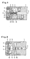
- a centering device for eyeglass lenses only one holder 1 is shown, which is one Longitudinal axis 2 controlled driven rotatable and perpendicular to this longitudinal axis 2 in all Directions driven controlled is displaceable.
- the carrier has one end a spherical cap-shaped ring bearing surface 3 and is inside with a first Provide slot guide 4, which runs perpendicular to the longitudinal axis 2.
- a spherical cap 5 complementary to the bearing surface, which with a receptacle 6 for a block or sucker 10 is provided.
- the receptacle 6 is provided with a for the angularly correct mounting of the block or suction device 10 transversely to the axis 2 extending pin 7 and a parallel and desaxed arranged Provide pin 8.
- the block or sucker 10 has corresponding, complementary ones Recesses so that it is only in a defined angular position in the receptacle 6 can be used.
- the block or sucker 10 is held in the receptacle 6 by means of an O-ring 9 held clamped.
- the block or sucker 10 has a contact surface 11 for a raw glass 12, which is either provided with an adhesive film, so that the raw glass 12 at Attaching the block or sucker 10 adheres adhesively, or the block or sucker is like this elastically deformable so that it adheres to the surface of the raw glass 12.
- a sliding block 13 is guided in the slot guide 4 and with a second, perpendicular thereto arranged sliding block 15 non-rotatably connected by a screw 16.
- the second sliding block 15 is guided in a second slot guide 14 in the spherical cap 5, whereby a gimbal mounting of the spherical cap 5 that is non-rotatable with respect to the carrier 1 given is.
- the radius R of the spherical cap-shaped bearing surface 3 and the spherical cap 5 is so dimensioned that its center point M in the longitudinal axis 2 of the carrier 1 on the contact surface 11 for the raw glass 12.
Landscapes
- Physics & Mathematics (AREA)
- Engineering & Computer Science (AREA)
- Mechanical Engineering (AREA)
- Geometry (AREA)
- Health & Medical Sciences (AREA)
- General Physics & Mathematics (AREA)
- Ophthalmology & Optometry (AREA)
- Optics & Photonics (AREA)
- Grinding And Polishing Of Tertiary Curved Surfaces And Surfaces With Complex Shapes (AREA)
Description
- Fig. 1
- einen Längsschnitt durch den erfindungsgemäßen Halter,
- Fig. 2
- einen um 90° gegenüber der Darstellung in Fig. 1 gedrehten Längsschnitt durch den erfindungsgemäßen Halter und
- Fig. 3
- einen erfindungsgemäßen Halter im Längsschnitt mit eingesetztem Block oder Sauger und einer Darstellung des Aufsetzens auf ein Rohglas.
Claims (3)
- Halter für einen Block oder Sauger (10) einer Zentriervorrichtung für Brillengläser mitgekennzeichnet durch eine kardanische Lagerung der Kugelkalotte (3) am Träger (I) mittels einer senkrecht zur Längsachse (2) im Träger (1) verlaufenden ersten Schlitzführung (4) für einen Gleitstein (13) und einer weiteren, zur ersten Schlitzführung (4) senkrecht verlaufenden zweiten Schlitzführung (14) in der Kugelkalotte (5) für einen zweiten Gleitstein (15), wobei die Gleitsteine (13, 15) eine undrehbare Verbindung der Kugelkalotte (5) mit dem Träger (1) bilden.einem Träger (1), der eine Längsachse (2) aufweist,einer kugelkalottenförmigen Lagerfläche (3) am Träger (1),einer am Träger (1) gelagerten, zur Lagerfläche (3) komplementären Kugelkalotte (5),einer Aufnahme (6) in der Kugelkalotte (5) für den Block oder Sauger (10) mit einer Anlagefläche (11) für ein Rohglas (12) undeinem Radius (R) der Lagerfläche (3) und der Kugelkalotte (5), dessen Mittelpunkt (M) in der Längsachse (2) des Trägers (1) auf der Anlagefläche (11) für das Rohglas (12) liegt,
- Halter nach Anspruch 1, bei dem die Aufnahme (6) in der Kugelkalotte (5) Einrichtungen (7, 8) zum winkelgerechten Halten eines Blocks oder Saugers (10) aufweist.
- Halter nach Anspruch 1 oder 2, bei dem der Träger (1) in der Zentriervorrichtung gesteuert angetrieben drehbar und in alle Richtungen senkrecht zu seiner Achse (2) angetrieben verschiebbar angeordnet ist.
Applications Claiming Priority (3)
| Application Number | Priority Date | Filing Date | Title |
|---|---|---|---|
| DE19954761 | 1999-11-15 | ||
| DE19954761A DE19954761C2 (de) | 1999-11-15 | 1999-11-15 | Halter für einen Block oder Sauger |
| PCT/EP2000/010666 WO2001036155A1 (de) | 1999-11-15 | 2000-10-30 | Halter für einen block oder sauger |
Publications (2)
| Publication Number | Publication Date |
|---|---|
| EP1232041A1 EP1232041A1 (de) | 2002-08-21 |
| EP1232041B1 true EP1232041B1 (de) | 2003-05-21 |
Family
ID=7929012
Family Applications (1)
| Application Number | Title | Priority Date | Filing Date |
|---|---|---|---|
| EP00975960A Expired - Lifetime EP1232041B1 (de) | 1999-11-15 | 2000-10-30 | Halter für einen block oder sauger |
Country Status (5)
| Country | Link |
|---|---|
| US (1) | US6855042B1 (de) |
| EP (1) | EP1232041B1 (de) |
| DE (1) | DE19954761C2 (de) |
| ES (1) | ES2198360T3 (de) |
| WO (1) | WO2001036155A1 (de) |
Families Citing this family (7)
| Publication number | Priority date | Publication date | Assignee | Title |
|---|---|---|---|---|
| DE102004023036A1 (de) * | 2004-05-06 | 2005-12-29 | Loh Engineering Ag, Oensingen | Blockstück zum Haltern eines optischen Werkstücks, insbesondere einer Brillenlinse, für dessen Bearbeitung |
| CN100341662C (zh) * | 2005-06-02 | 2007-10-10 | 林仙根 | 雕铣机万向斜度头 |
| US8951097B2 (en) * | 2009-12-24 | 2015-02-10 | Essilor International (Compagnie Generale D'optique) | Method for mounting an optical lens to be polished |
| CN103143958B (zh) * | 2013-04-08 | 2015-01-28 | 哈尔滨集睿谱光电技术有限公司 | 具有万向调节功能和自锁功能的超精密加工用卡具 |
| TWI584914B (zh) * | 2013-07-22 | 2017-06-01 | 佳能股份有限公司 | 元件製造方法及拋光裝置 |
| CN112589623B (zh) * | 2020-12-30 | 2022-06-24 | 青岛三联金属结构有限公司 | 一种手工自动双模式自由切换的打磨装置 |
| CN117399834B (zh) * | 2023-12-13 | 2024-03-08 | 四川惠科达仪表制造有限公司 | 一种具有定位功能的法兰钢管总成智能焊接装置 |
Family Cites Families (7)
| Publication number | Priority date | Publication date | Assignee | Title |
|---|---|---|---|---|
| US2383131A (en) * | 1942-12-01 | 1945-08-21 | C P Goerz American Optical Com | Apparatus for polishing optical flats |
| US3134208A (en) * | 1962-01-08 | 1964-05-26 | Clyde S Mccain | Lens holding device |
| FR2154320B1 (de) | 1971-09-29 | 1974-05-10 | Lunetiers | |
| FR2226824A5 (en) | 1973-04-18 | 1974-11-15 | Asselin Ets | Soft jawed clamp gripping lenses - has inclinable jaw for clamping of prismatic lens for edge bevelling etc |
| DE2621891C3 (de) | 1976-05-17 | 1981-03-19 | Dollond and Aitchisen (Services) Ltd., Yardley, Birmingham, West Midlands | Linsenrandschleifmaschine und zugehöriger Linsenträger |
| FR2366103A1 (fr) | 1976-05-18 | 1978-04-28 | Essilor Int | Bloc de montage d'une lentille sur une machine a deborder et biseauter les lentilles ophtalmiques |
| FR2682058B1 (fr) | 1991-10-04 | 1993-12-10 | Buchmann Optical Engineering | Appareil pour relver la topographie de la face convexe d'un verre optique et machine de pose d'un adaptateur integrant un tel appareil. |
-
1999
- 1999-11-15 DE DE19954761A patent/DE19954761C2/de not_active Expired - Fee Related
-
2000
- 2000-10-30 US US10/130,162 patent/US6855042B1/en not_active Expired - Fee Related
- 2000-10-30 WO PCT/EP2000/010666 patent/WO2001036155A1/de not_active Ceased
- 2000-10-30 ES ES00975960T patent/ES2198360T3/es not_active Expired - Lifetime
- 2000-10-30 EP EP00975960A patent/EP1232041B1/de not_active Expired - Lifetime
Also Published As
| Publication number | Publication date |
|---|---|
| WO2001036155A1 (de) | 2001-05-25 |
| DE19954761C2 (de) | 2001-10-25 |
| EP1232041A1 (de) | 2002-08-21 |
| US6855042B1 (en) | 2005-02-15 |
| ES2198360T3 (es) | 2004-02-01 |
| DE19954761A1 (de) | 2001-05-31 |
Similar Documents
| Publication | Publication Date | Title |
|---|---|---|
| DE4414784C2 (de) | Anlage zum Schleifen des Umfangsrandes und/ oder einer optischen Oberfläche von Brillengläsern | |
| DE4127094C2 (de) | Anlage zum Schleifen der optischen Oberflächen und/oder des Umfangsrandes von Brillengläsern | |
| DE19527222C2 (de) | Anlage zum Schleifen wenigstens des Umfangsrandes von Brillengläsern und Verfahren zum rechnerischen Berücksichtigen der Position eines an einem Haltekopf der Anlage gehaltenen Brillenglasrohlings | |
| DE19702287C2 (de) | Verfahren zum Ermitteln des Facettenverlaufs auf dem Rand von formzubearbeitenden Brillengläsern und zum Steuern des Formbearbeitens entsprechend dem ermittelten Facettenverlauf | |
| DE1752002A1 (de) | Verfahren und Vorrichtung zur Herstellung von Linsen | |
| DE3587514T3 (de) | Verfahren und Vorrichtung zum Berechnen der Beziehung zwischen der Rohlinse und der Brillenlinse. | |
| DE10013650C1 (de) | Verfahren zum Bearbeiten von Brillengläsern mittels einer CNC-gesteuerten Brillenglasbearbeitungsmaschine und Vorrichtung zur Durchführung des Verfahrens | |
| DE4224640A1 (de) | Geraet fuer die automatische messung der form und/oder des profils der innenkontur eines brillenfassungsrahmens | |
| DE19954761C2 (de) | Halter für einen Block oder Sauger | |
| DE602005006319T2 (de) | Verfahren und vorrichtung zur montagevorbereitung zum einsatz zweier ophthalmischer linsen in der selben brille | |
| EP1094917B1 (de) | Aufnahmevorrichtung für ein brillenglas | |
| DE10013648A1 (de) | Anlage zum Formbearbeiten der Ränder von Brillengläsern | |
| DE19505524C2 (de) | Vorrichtung zum Zentrieren eines Brillenglasrohlings und Anbringen eines Halteteils auf einer optischen Oberfläche des Brillenglasrohlings | |
| EP1581364B1 (de) | Verfahren zur parallaxefreien zentrierung eines optischen elementes | |
| DE4214242A1 (de) | Verfahren, block oder sauger und maschine zum bearbeiten des randes von brillenglaesern | |
| DE3530649C2 (de) | ||
| DE2619985A1 (de) | Vorrichtung zur befestigung eines brillenglases in einer brillenglasrandschleifmaschine und verfahren zur anwendung dieser vorrichtung | |
| DE1947009A1 (de) | Vorrichtung zum Halten von optischen Linsen bei der Randbearbeitung in Schleifmaschinen | |
| DE2621891A1 (de) | Linsentraeger und linsen-herstellungsverfahren | |
| EP0690767B1 (de) | Vorrichtung zum facettieren von brillengläsern | |
| DE4214427B4 (de) | Einrichtung zum selbsttätigen Beschicken von Vorrichtungen zur Bearbeitung von Brillengläsern | |
| EP3585563A1 (de) | Blockstück zum blocken einer linse | |
| DE1289331B (de) | Brille mit einem Vergroesserungsaufsatz | |
| DE19736789C2 (de) | Brillenglasbearbeitungsmaschine | |
| DE4020597C2 (de) | Vorrichtung zur paarweisen Bearbeitung der Umfangsfläche von Brillengläsern |
Legal Events
| Date | Code | Title | Description |
|---|---|---|---|
| PUAI | Public reference made under article 153(3) epc to a published international application that has entered the european phase |
Free format text: ORIGINAL CODE: 0009012 |
|
| 17P | Request for examination filed |
Effective date: 20020611 |
|
| AK | Designated contracting states |
Kind code of ref document: A1 Designated state(s): AT BE CH CY DE DK ES FI FR GB GR IE IT LI LU MC NL PT SE |
|
| GRAH | Despatch of communication of intention to grant a patent |
Free format text: ORIGINAL CODE: EPIDOS IGRA |
|
| GRAH | Despatch of communication of intention to grant a patent |
Free format text: ORIGINAL CODE: EPIDOS IGRA |
|
| GRAA | (expected) grant |
Free format text: ORIGINAL CODE: 0009210 |
|
| AK | Designated contracting states |
Designated state(s): ES FR |
|
| REG | Reference to a national code |
Ref country code: IE Ref legal event code: FG4D Free format text: GERMAN |
|
| REG | Reference to a national code |
Ref country code: IE Ref legal event code: FD4D Ref document number: 1232041E Country of ref document: IE |
|
| REG | Reference to a national code |
Ref country code: ES Ref legal event code: FG2A Ref document number: 2198360 Country of ref document: ES Kind code of ref document: T3 |
|
| RAP2 | Party data changed (patent owner data changed or rights of a patent transferred) |
Owner name: WECO OPTIK GMBH |
|
| PLBE | No opposition filed within time limit |
Free format text: ORIGINAL CODE: 0009261 |
|
| STAA | Information on the status of an ep patent application or granted ep patent |
Free format text: STATUS: NO OPPOSITION FILED WITHIN TIME LIMIT |
|
| REG | Reference to a national code |
Ref country code: ES Ref legal event code: PC2A |
|
| ET | Fr: translation filed | ||
| 26N | No opposition filed |
Effective date: 20040224 |
|
| PGFP | Annual fee paid to national office [announced via postgrant information from national office to epo] |
Ref country code: ES Payment date: 20110121 Year of fee payment: 11 |
|
| PGFP | Annual fee paid to national office [announced via postgrant information from national office to epo] |
Ref country code: FR Payment date: 20111110 Year of fee payment: 12 |
|
| REG | Reference to a national code |
Ref country code: ES Ref legal event code: FD2A Effective date: 20130702 |
|
| REG | Reference to a national code |
Ref country code: FR Ref legal event code: ST Effective date: 20130628 |
|
| PG25 | Lapsed in a contracting state [announced via postgrant information from national office to epo] |
Ref country code: ES Free format text: LAPSE BECAUSE OF NON-PAYMENT OF DUE FEES Effective date: 20111031 |
|
| PG25 | Lapsed in a contracting state [announced via postgrant information from national office to epo] |
Ref country code: FR Free format text: LAPSE BECAUSE OF NON-PAYMENT OF DUE FEES Effective date: 20121031 |