EP1225046A1 - Druckzylinder zum Aufnehmen einer Druckhülse - Google Patents
Druckzylinder zum Aufnehmen einer Druckhülse Download PDFInfo
- Publication number
- EP1225046A1 EP1225046A1 EP02001411A EP02001411A EP1225046A1 EP 1225046 A1 EP1225046 A1 EP 1225046A1 EP 02001411 A EP02001411 A EP 02001411A EP 02001411 A EP02001411 A EP 02001411A EP 1225046 A1 EP1225046 A1 EP 1225046A1
- Authority
- EP
- European Patent Office
- Prior art keywords
- cylinder
- flow
- sleeve
- printing
- pressure
- Prior art date
- Legal status (The legal status is an assumption and is not a legal conclusion. Google has not performed a legal analysis and makes no representation as to the accuracy of the status listed.)
- Granted
Links
- 238000007639 printing Methods 0.000 title claims description 50
- 238000000034 method Methods 0.000 claims abstract description 8
- 239000012530 fluid Substances 0.000 claims description 35
- 238000007645 offset printing Methods 0.000 claims description 8
- 238000006073 displacement reaction Methods 0.000 claims description 5
- 239000004753 textile Substances 0.000 claims description 4
- 239000002657 fibrous material Substances 0.000 claims description 3
- 239000000463 material Substances 0.000 claims description 2
- 230000015572 biosynthetic process Effects 0.000 description 2
- 238000007664 blowing Methods 0.000 description 2
- 210000003027 ear inner Anatomy 0.000 description 2
- 238000006243 chemical reaction Methods 0.000 description 1
- 238000010276 construction Methods 0.000 description 1
- 230000000694 effects Effects 0.000 description 1
- 238000003780 insertion Methods 0.000 description 1
- 230000037431 insertion Effects 0.000 description 1
- 238000009434 installation Methods 0.000 description 1
- 238000012423 maintenance Methods 0.000 description 1
- 238000004519 manufacturing process Methods 0.000 description 1
- 239000002184 metal Substances 0.000 description 1
- 230000002093 peripheral effect Effects 0.000 description 1
- 239000004033 plastic Substances 0.000 description 1
- 238000009420 retrofitting Methods 0.000 description 1
- 238000004513 sizing Methods 0.000 description 1
Images



Classifications
-
- B—PERFORMING OPERATIONS; TRANSPORTING
- B41—PRINTING; LINING MACHINES; TYPEWRITERS; STAMPS
- B41F—PRINTING MACHINES OR PRESSES
- B41F30/00—Devices for attaching coverings or make-ready devices; Guiding devices for coverings
- B41F30/04—Devices for attaching coverings or make-ready devices; Guiding devices for coverings attaching to transfer cylinders
-
- B—PERFORMING OPERATIONS; TRANSPORTING
- B41—PRINTING; LINING MACHINES; TYPEWRITERS; STAMPS
- B41P—INDEXING SCHEME RELATING TO PRINTING, LINING MACHINES, TYPEWRITERS, AND TO STAMPS
- B41P2227/00—Mounting or handling printing plates; Forming printing surfaces in situ
- B41P2227/20—Means enabling or facilitating exchange of tubular printing or impression members, e.g. printing sleeves, blankets
Definitions
- the present invention relates to a pressure cylinder for receiving an axially positionable and / or axially displaceable pressure sleeve according to the preamble of Claim 1.
- the present invention relates to a method for axial positioning and / or moving a printing sleeve on a printing cylinder according to the preamble of claim 14.
- Tubular or sleeve-shaped pressure sleeves e.g. Blankets for the Offset printing as described in US 5,215,013 are applied axially to a cylinder applied and removed from this.
- Blankets for the Offset printing as described in US 5,215,013 are applied axially to a cylinder applied and removed from this.
- a rubber blanket in that Described patent are usually openings or air holes on the Operator side of the blanket cylinder arranged to apply pressure to the inside of the Blanket to act on when the blanket is axially from the blanket cylinder removed or applied to it.
- Blankets can stick if they remain attached for too long because Air pressure from the air holes can be blocked and the drive side of the cylinder do not reach.
- the placement of holes is due to use difficult only a series of air holes on the operator side; it could also happen that the sleeve does not inflate or expand at all. Holes not placed correctly can cause air to simply escape from the operator side of the sleeve without the Inflate and expand the drive side of the sleeve.
- a single row of holes on the Operator can inflate only one of the blankets on operator side, so that other blankets closer to the drive side cannot be removed.
- a turning bar pressurized with compressed air which e.g. in the Folder superstructure of a rotary printing press can be used, known which are arranged adjacent on their peripheral surface in the axial direction Has air outlet openings from which blown air emerges and between the surface an air cushion to the turning bar and a paper web guided around the turning bar non-contact transport of the paper web builds up.
- the individual air outlet openings The turning bar are provided with valves, the valves having two switching states can take. In the first state in which the air outlet opening is not one The paper web is covered, blown air exits through a duct in the valve, while the valve itself closes the air outlet opening and thus a reinforced one Blowing air prevented.
- a device for treating webs is known from US 2,828,553, wherein a roller with air outlet openings arranged on the circumference of the roller is provided and is used to transport a train.
- the air outlet openings can be equipped with ball valves, the ball valves being designed such that a contact of the web with a section of the ball valve, which extends over the Surface of the roller extends beyond, to a displacement of the ball within the Valve leads, which moves the valve from a closed to an open state transforms.
- Another object of the present invention is fluid assisted removal or applying more than one printing sleeve to the printing cylinder in a trouble-free manner Way to enable.
- the impression cylinder according to the invention in particular a blanket cylinder, for receiving an axially positionable and / or axially displaceable pressure sleeve, in particular Blanket sleeve, with a cylinder body having an outer surface, wherein the outer surface comprises at least one opening, and with a feed, in particular a supply line for supplying fluid, in particular air, to the at least one opening, is characterized in that the supply at least has a flow limiter, which the fluid flow depending on the changed axial position of the pressure sleeve.
- the fluid flow through at least one Flow limiter changed depending on the axial position of the pressure sleeve, whereby the jamming of the pressure sleeve can be prevented in an advantageous manner.
- the flow limiter enables the escape of fluid, especially air, for the trouble-free positioning or displacement of the pressure sleeve, in the other case, if the opening is not covered by the pressure sleeve, the Flow limiter advantageously the fluid flow through the supply or out limited or even reduced the opening in the surface of the impression cylinder, so that on a simple way to avoid a drop in pressure due to the fluid flowing out unchecked can.
- the pressure drop in a connected to the pressure cylinder Fluid reservoir e.g. a compressed air tank
- the flow restrictor which limits the fluid flow in Changes depending on the axial position of the pressure sleeve can thus be advantageous for automatic flow control in the feed or in the opening of the Surface of the impression cylinder.
- a printing sleeve which is pushed onto the printing cylinder or is removed from it, regardless of its current position on the impression cylinder always with the necessary amount of compressed air through the opening in the surface of the Pressurized pressure cylinder and thereby ensures that the pressure sleeve in necessary stretched, and a trouble-free and reduced friction Moving the pressure sleeve is advantageously possible.
- the printing cylinder according to the invention also has the advantage that the Flow restrictor vortex generated when the at least one opening at least is not partially covered by the pressure sleeve.
- the flow limiter has a plurality of Has slats.
- a flow limiter with a large number of fins is simple producible and insertable into the surface of the printing cylinder. This allows one simple construction of the flow limiter without moving parts using the Flow conditions inside the flow restrictor generating Fluid vortex can be caused.
- the ends can be one another opposite slats be spaced such that they have a free channel for the Form fluid flow.
- the flow limiter prevents flow Objects and / or textile material and / or fiber material includes.
- the flow restrictor can comprise a valve which, depending on the axial position of the pressure sleeve is open or at least largely closed.
- valves which like the above mentioned vortex generating flow limiter depending on the axial Position of the pressure sleeve limit the flow of fluid, in particular air.
- a device is also used when using valves to limit the flow provided which the displacement of a pressure sleeve without problems and allows for reduced friction in any position of the pressure sleeve. In advantageous Additional control devices and sensors can thus be dispensed with become.
- the at least one opening may comprise a plurality of openings which are in Circumferential direction offset on the outer surface of the cylinder body are.
- the plurality of openings is assigned to a pressure sleeve.
- the at least one opening has a plurality of Includes openings which are offset in the axial direction on the outer surface of the Cylinder body are arranged.
- the Pressure sleeves can be positioned axially offset on the pressure cylinder.
- the at least one opening be arranged in the region of the drive-side end section of the printing cylinder and in The area of the operator-side end section of the printing cylinder can have further openings be arranged.
- a printing press according to the invention in particular offset printing press or Web-fed rotary offset printing machine, with a compressed air supply, is characterized by a first impression cylinder and at least one second impression cylinder as above described from.
- a method for axially positioning and / or moving one Printing sleeve, in particular blanket sleeve, on a printing cylinder, in particular Blanket cylinder, the impression cylinder having an outer surface comprises at least one opening having a cylinder body, and wherein one Supply, in particular a supply line, for supplying fluid, in particular Air to which at least one opening is provided is distinguished by providing fluid pressure on an inside of the pressure sleeve by means of the at least an opening, axial displacement or positioning of the pressure sleeve, and automatic Limiting the flow through the at least one opening by means of a Flow limiter, which determines the fluid flow depending on the axial position of the Pressure sleeve changed, off.
- one Supply in particular a supply line, for supplying fluid, in particular Air to which at least one opening is provided is distinguished by providing fluid pressure on an inside of the pressure sleeve by means of the at least an opening, axial displacement or positioning of the pressure sleeve, and automatic Limiting the flow through
- the method according to the invention is accompanied by advantages such as those above have been described with regard to the printing cylinder according to the invention.
- the step of automatically limiting the Flow includes the formation of fluid vortices.
- the step of automatically limiting the flow includes at least largely closing a valve.
- Fig. 1 shows a schematic view of the drive side of an inventive Offset printing machine 1.
- a web 5 runs through a nip, which is from a first sleeve-shaped rubber blanket 12 and a second sleeve-shaped rubber blanket 62 is formed, and then through a second gap formed by a third sleeve-shaped rubber blanket 112 and a fourth sleeve-shaped rubber blanket 162 is formed.
- the blanket 12 is axially attached to a blanket cylinder 10
- the Flow restrictor as described with reference to FIG. 2, includes Blanket 62 is axially attached to a similar blanket cylinder 59.
- the Plate cylinders 8, 58 contact the rubber blankets 12, 62, respectively, for a colored one Create image on the rubber blankets, the image then transferred to the web 5 becomes.
- the rubber blankets 12, 62, 112, 162 are through openings on the operator side of the Frame of the printing press 1 with the aid of compressed air, each through openings in the blanket cylinders 10, 60, 119, 160 is supplied axially removable.
- Compressor 80 guides the blanket cylinders 12, 62, 112, 162 through a feed line 90 air closed. There are preferably no valves or separators in the feed line 90 is provided so that all four cylinders 10, 60, 110, 160 are supplied with air at the same time becomes.
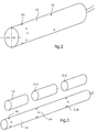
- Fig. 2 shows one of the blanket cylinders 10 with a plurality of openings in the form of air holes or nozzles 14 on the operator side of the blanket cylinder 10. If the blanket 12 is removed from or applied to the cylinder, are the Holes 14 are normally covered unless the blanket is completely removed. To remove and apply the rubber blanket 12 from or to the Supporting blanket cylinders 10 is an additional series of flow-limited openings in the form of holes or nozzles 16 are provided.
- the Holes 16 are axial between the first row of operator side holes 14 and the Drive side of the cylinder arranged.
- the additional holes 16 include at least a hole that is located closer to the drive side of the cylinder than to the operator side is.
- the flow-restricted holes 16 have a supply line or an inlet 70 with a flow limiter 78 in the supply line 70.
- the flow restrictor 78 can be part of the cylinder 10 or be removable from it.
- the flow limiter 78 in this embodiment comprises a plurality of opposing fins 76, the tips of which form a free or open channel d, ie a free flow channel, if there are no eddies.
- All holes that are not located near the operator-side holes can Have flow limiter 78.
- the operator-side holes 14 can also Have flow restrictors or not.
- FIG. 3 shows a blanket cylinder 10 for a plurality of sleeve-shaped blankets 12, 212, 312, which are shown schematically above the cylinder 10.
- Applying blankets 12, 212, 312 to the cylinder 10 slides the blanket 312 over the operator side holes 14, then over a second row of holes 114 and comes to a standstill so that the operator-side end of the rubber blanket 312 over one third row of holes 214 is arranged.
- the rubber blanket 212 is arranged so that it is next to the rubber blanket 312, the operator end of the Blanket 212 lies over the second row of holes 114.
- the rubber blanket 12 lies on the operator end above the holes 14. All holes in this Embodiment can have flow restrictors. Additional holes with Flow restrictors could also be between rows 14, 114, 214 of holes be arranged.
- FIG. 5 to 9 show further embodiments of a flow limiter 60, which in the Space 50 between the outer surface of cylinder 10 and a second inner one Layer 65 of the cylinder 10 is arranged.
- the flow restrictor 60 in the embodiment of FIG. 5 includes before Exit hole 16 flow obstructing objects 63 in an air or fluid supply 70.
- Fig. 6 shows another embodiment with a textile flow restrictor 60, e.g. made of fleece or a textile or fibrous material.
- a textile flow restrictor 60 e.g. made of fleece or a textile or fibrous material.
- FIG. 7a and 7b show a top view and a side view of a labyrinth-shaped Flow limiter 60 in room 50.
- a labyrinth-shaped Flow limiter 60 in room 50.
- Figures 8a and 8b show a top view and a side view of another labyrinth-shaped flow limiter 60, which is arranged in space 50.
- FIG. 9 shows a sandwich-shaped flow restrictor 60 in space 50, wherein alternately holes are arranged on the different sides of the sandwich layers.
- FIG. 10 shows a further embodiment of the printing cylinder 10 according to the invention, a flow limiter 78 in the form of a with a ball 400 in the pressure cylinder Ball valve provided.
- the ball 400 is within the Flow limiter 78 is movably arranged so that it depends on the Position of a pressure sleeve 12 throttle the fluid flow through the flow restrictor 78 can.
- the fluid is supplied via a supply line or an inlet 70 Flow limiter 78 is supplied and flows around the ball 400.
- the pressure sleeve 12 is in a position such that the opening 60 through the Pressure sleeve 12 is covered, so it occurs in the space between the pressure sleeve 12 and the pressure cylinder 10 to build up a compressed air cushion and thus one Pressure increase, so that the ball 400, which is to be regarded as a valve element, at least is moved slightly into the interior of the compressed air limiter 78. As a result, can the fluid flow, e.g. an air stream, wash around the ball 400 and out of the opening 16 escape.
- the fluid flow e.g. an air stream
- the pressure sleeve 12 is moved into a position so that it No longer covers opening 16, the valve element 400 is only from the inlet side 70 pressurized with a fluid pressure so that it is in relation to the pressure cylinder 10 moved outwards and at least largely closes the opening 16.
- a channel 402 can be provided in the valve element or in the ball 400 form, through which even in the closed state of the valve element Fluid flow reaches the outside area, which means that when it covers the opening 16 a pressure sleeve 12 in turn for building an air cushion and thereby for Pushing down the ball 400 comes.
- the valve element 400 can deviate from the spherical shape shown in FIG. 10 also take any other form that allows the valve element to move within the flow restrictor 78, e.g. also an elongated shape or conical shape conceivable.
- the additional supply channel 42 can take place in the valve element 400 also formed as a bypass to the valve element 400 in the flow limiter 78 his.
- the flow restrictors can form a part with the cylinder or can be used as Insertion elements can be formed in the existing holes in a cylinder be pressed or screwed. This makes it easier to manufacture new ones Cylinders and also easier conversion or retrofitting of existing cylinders.
- the Flow restrictors can be made of plastic or a metal. flow of another form, e.g. slats 76 of square or triangular design in FIG. 4, can also be used.
- the present invention has particular advantages when used in a printing press with a variety of pressure cylinders powered by a single pressure source be used.
- the pressure from the pressure source can thus be on a sufficient level is maintained even if different blankets or other sleeves are removed. Even if several sleeves from different cylinders, e.g. even cylinders of different printing units are removed, there is no uncontrolled outflow of fluid.
Landscapes
- Rotary Presses (AREA)
- Rolls And Other Rotary Bodies (AREA)
- Supply, Installation And Extraction Of Printed Sheets Or Plates (AREA)
- Printing Plates And Materials Therefor (AREA)
- Pens And Brushes (AREA)
- Diaphragms For Electromechanical Transducers (AREA)
Abstract
Description
- Fig. 1
- eine schematische Ansicht einer erfindungsgemäßen Offsetdruckmaschine, in der eine einzelne Luftquelle, z.B. ein Kompressor, vier verschiedene Gummituchzylinder versorgt,
- Fig. 2
- einen erfindungsgemäßen Gummituchzylinder für ein einzelnes Gummituch,
- Fig. 3
- einen erfindungsgemäßen Gummituchzylinder für mehrere Gummitücher,
- Fig. 4a und 4b
- eine erste Ausführungsform eines erfindungsgemäßen Durchflussbegrenzers für die durchflussbegrenzten Öffnungen bzw. Luftlöcher des Zylinders, wobei in Fig. 4a ein Gummituch über dem Loch angeordnet ist, und in Fig. 4b das Gummituch nicht über dem Loch angeordnet ist,
- Fig. 5
- eine weitere Ausführungsform des erfindungsgemäßen Durchflussbegrenzers des Zylinders,
- Fig. 6
- eine weitere Ausführungsform des erfindungsgemäßen Durchflussbegrenzers des Zylinders,
- Fig. 7a und 7b
- eine Draufsicht und eine Seitenansicht einer weiteren Ausführungsform des erfindungsgemäßen Durchflussbegrenzers des Zylinders, wobei Fig. 7a die Ansicht durch den Schnitt VI a - VI a von Fig. 7b und Fig. 7b die Ansicht durch den Schnitt VI b - VI b aus Fig. 7a zeigt,
- Fig. 8a und 8b
- eine Draufsicht und eine Seitenansicht einer weiteren Ausführungsform des erfindungsgemäßen Durchflussbegrenzers des Zylinders, wobei Fig. 8a die Ansicht durch den Schnitt VII a - VII a von Fig. 8b und Fig. 8a die Ansicht durch den Schnitt VII b - VII b von Fig. 8a zeigt,
- Fig. 9
- eine weitere Ausführungsform des erfindungsgemäßen Durchflussbegrenzers des Zylinders, und
- Fig. 10
- eine weitere Ausführungsform eines erfindungsgemäßen Durchflussbegrenzers in Form eines Kugelventils.
- 1
- Druckmaschine
- 2
- Bewegungsrichtung
- 5
- Bahn
- 8
- Plattenzylinder
- 10
- Gummituchzylinder
- 12
- erstes hülsenförmiges Gummituch
- 14
- Luftlöcher oder -düsen / Öffnungen
- 16
- Luftlöcher oder -düsen / Öffnungen
- 50
- Raum
- 58
- Plattenzylinder
- 59
- Gummituchzylinder
- 60
- Durchflussbegrenzer
- 62
- zweites hülsenförmiges Gummituch
- 63
- strömungsbehindernde Objekte
- 65
- zweite innere Schicht
- 70
- Versorgungsleitung / Einlass
- 76
- Lamellen
- 78
- Durchflussbegrenzer
- 80
- Kompressor
- 90
- Zuführleitung / Zuführung
- 110
- Gummituchzylinder
- 114
- zweite Reihe von Löchern / Öffnungen
- 112
- drittes hülsenförmiges Gummituch
- 160
- Gummituchzylinder
- 162
- viertes hülsenförmiges Gummituch
- 212
- hülsenförmiges Drucktuch
- 214
- dritte Reihe von Löchern /Öffnungen
- 312
- hülsenförmiges Drucktuch
- 400
- Kugel/Ventilelement
- 402
- Kanal
- d
- Öffnung / freier Kanal
Claims (16)
- Druckzylinder, insbesondere Gummituchzylinder (10), zum Aufnehmen einer axial positionierbaren und/oder axial verschiebbaren Druckhülse, insbesondere Gummituchhülse (12), mit einem eine äußere Oberfläche aufweisenden Zylinderkörper, wobei die äußere Oberfläche mindestens eine Öffnung (14) umfasst, und mit einer Zuführung (90), insbesondere einer Versorgungsleitung (70), zum Zuführen von Fluid, insbesondere Luft, zu der mindestens einen Öffnung (14),
dadurch gekennzeichnet, dass die Zuführung (70, 90) mindestens einen Durchflussbegrenzer (60, 78) aufweist, welcher den Fluidfluss in Abhängigkeit von der axialen Position der Druckhülse (12) verändert. - Druckzylinder nach Anspruch 1,
dadurch gekennzeichnet, dass der Durchflussbegrenzer (60, 78) Wirbel erzeugt, wenn die mindestens eine Öffnung (14) zumindest teilweise nicht durch die Druckhülse (12) bedeckt ist. - Druckzylinder nach Anspruch 1 oder 2,
dadurch gekennzeichnet, dass der Durchflussbegrenzer (60, 78) eine Vielzahl von Lamellen (76) aufweist. - Druckzylinder nach einem der Ansprüche 1 bis 3,
dadurch gekennzeichnet, dass die Enden einander gegenüberliegender Lamellen (76) derart beabstandet sind, dass sie einen freien Kanal (d) für den Fluidfluss bilden. - Druckzylinder nach Anspruch 1 oder 2,
dadurch gekennzeichnet, dass der Durchflussbegrenzer (60, 78) strömungsbehindernde Objekte und/oder textiles Material und/oder Fasermaterial umfasst. - Druckzylinder nach Anspruch 1,
dadurch gekennzeichnet, dass der Durchflussbegrenzer (60, 78) ein Ventil umfasst, welches in Abhängigkeit von der axialen Position der Druckhülse (12) geöffnet oder zumindest weitgehend geschlossen ist. - Druckzylinder nach einem der vorhergehenden Ansprüche,
dadurch gekennzeichnet, dass die mindestens eine Öffnung eine Vielzahl von Öffnungen (14) umfasst, welche in Umfangsrichtung versetzt auf der äußeren Oberfläche des Zylinderkörpers angeordnet sind. - Druckzylinder nach Anspruch 7,
dadurch gekennzeichnet, dass die Vielzahl von Öffnungen (14) einer Druckhülse (12) zugeordnet ist. - Druckzylinder nach einem der vorhergehenden Ansprüche,
dadurch gekennzeichnet, dass die mindestens eine Öffnung eine Vielzahl von Öffnungen (14, 16, 114, 214) umfasst, welche in axialer Richtung versetzt auf der äußeren Oberfläche des Zylinderkörpers angeordnet sind. - Druckzylinder nach Anspruch 9,
dadurch gekennzeichnet, dass die Vielzahl von Öffnungen (14, 16, 114, 214) verschiedenen Druckhülsen (12, 212, 312) zugeordnet ist. - Druckzylinder nach einem der vorhergehenden Ansprüche,
dadurch gekennzeichnet, dass mindestens eine der Vielzahl von Öffnungen (14) einer ersten Druckhülse (12) zugeordnet ist und dass mindestens eine weitere der Vielzahl von Öffnungen (114) einer weiteren Druckhülse (212) zugeordnet ist, wobei die Druckhülsen axial versetzt auf dem Druckzylinder positionierbar sind. - Druckzylinder nach einem der vorhergehenden Ansprüche,
dadurch gekennzeichnet, dass die mindestens eine Öffnung (16) im Bereich des antriebsseitigen Endabschnitts des Druckzylinders angeordnet ist und dass im Bereich des bedienerseitigen Endabschnitts des Druckzylinders weitere Öffnungen vorgesehen sind. - Druckmaschine, insbesondere Offsetdruckmaschine oder Rollenrotationsoffsetdruckmaschine, mit einer Druckluftversorgung (80, 90),
gekennzeichnet durch
einen ersten Druckzylinder (10, 59) nach einem der vohergehenden Ansprüche und mindestens einen zweiten Druckzylinder (110, 160) nach einem der vorhergehenden Ansprüche. - Verfahren zum axialen Positionieren und/oder Verschieben einer Druckhülse, insbesondere Gummituchhülse (12), auf einem Druckzylinder, insbesondere Gummituchzylinder (10), wobei der Druckzylinder einen eine äußere Oberfläche mit mindestens einer Öffnung (14) aufweisenden Zylinderkörper umfasst, und wobei eine Zuführung (90), insbesondere eine Versorgungsleitung (70), zum Zuführen von Fluid, insbesondere Luft, zu der mindestens einen Öffnung (14) vorgesehen ist,
gekennzeichnet durch:Vorsehen von Fluiddruck auf einer Innenseite der Druckhülse (12) mittels der mindestens einen Öffnung (14);Axiales Verschieben oder Positionieren der Druckhülse (12); undSelbsttätiges Begrenzen des Durchflusses durch die mindestens eine Öffnung (14) mittels eines Durchflussbegrenzer (60, 78), welcher den Fluidfluss in Abhängigkeit von der axialen Position der Druckhülse (12) verändert. - Verfahren nach Anspruch 12,
dadurch gekennzeichnet, dass der Schritt des selbsttätigen Begrenzens des Durchflusses das Bilden von Fluidwirbeln umfasst. - Verfahren nach Anspruch 12,
dadurch gekennzeichnet, dass der Schritt des selbsttätigen Begrenzens des Durchflusses das zumindest weitgehende Schließen eines Ventils umfasst.
Applications Claiming Priority (2)
| Application Number | Priority Date | Filing Date | Title |
|---|---|---|---|
| US767108 | 2001-01-22 | ||
| US09/767,108 US7107907B2 (en) | 2001-01-22 | 2001-01-22 | Flow-restricted printing cylinder for a removable printing sleeve |
Publications (2)
| Publication Number | Publication Date |
|---|---|
| EP1225046A1 true EP1225046A1 (de) | 2002-07-24 |
| EP1225046B1 EP1225046B1 (de) | 2010-08-18 |
Family
ID=25078499
Family Applications (1)
| Application Number | Title | Priority Date | Filing Date |
|---|---|---|---|
| EP02001411A Expired - Lifetime EP1225046B1 (de) | 2001-01-22 | 2002-01-21 | Druckzylinder zum Aufnehmen einer Druckhülse |
Country Status (5)
| Country | Link |
|---|---|
| US (2) | US7107907B2 (de) |
| EP (1) | EP1225046B1 (de) |
| JP (1) | JP4272836B2 (de) |
| AT (1) | ATE477928T1 (de) |
| DE (2) | DE10202254A1 (de) |
Cited By (1)
| Publication number | Priority date | Publication date | Assignee | Title |
|---|---|---|---|---|
| EP1636033B1 (de) * | 2002-12-13 | 2011-08-24 | Laurent De Volder | Rotationstampondruckmaschine zum bedrucken von gegenständen mit begrenzter flexibilität |
Families Citing this family (15)
| Publication number | Priority date | Publication date | Assignee | Title |
|---|---|---|---|---|
| FR2843071B1 (fr) * | 2002-08-02 | 2005-02-18 | Komori Chambon | Perfectionnements aux machines d'impression |
| DE102004004396A1 (de) * | 2004-01-29 | 2005-08-11 | Heidelberger Druckmaschinen Ag | Vorrichtung zur Erzeugung gedrosselter Blas- oder Saugluft |
| EP1990191A3 (de) * | 2007-05-08 | 2010-12-01 | manroland AG | Rollendruckmaschine |
| DE102007047781A1 (de) * | 2007-05-08 | 2008-11-13 | Manroland Ag | Rollendruckmaschine |
| US20090211475A1 (en) | 2008-02-21 | 2009-08-27 | Taylor Bradley K | Extended print sleeve and method for preparing a printing form from the sleeve |
| DE102008022635A1 (de) * | 2008-05-08 | 2009-11-12 | Manroland Ag | Rollendruckmaschine |
| EP2191969B1 (de) | 2008-11-26 | 2012-09-19 | Agfa Graphics N.V. | Hülsen und Hülsensegmente für die Flexografie |
| US8307764B2 (en) * | 2009-02-17 | 2012-11-13 | Luminite Products Corporation | Printing sleeve |
| DE102009002691B4 (de) * | 2009-04-28 | 2013-03-21 | Isimat Gmbh Siebdruckmaschinen | Haltedorn für zu bedruckende Gegenstände |
| TW201129478A (en) * | 2009-12-21 | 2011-09-01 | Sakamoto Jun | Offset roll, method for producing offset roll, and gravure offset printing device |
| US9120302B2 (en) | 2012-04-30 | 2015-09-01 | Rossini S.P.A. | Bridge sleeves with diametrically expandable stabilizers |
| US9126395B2 (en) | 2012-04-30 | 2015-09-08 | Rossini S.P.A. | Bridge sleeves with diametrically expandable stabilizers |
| JP5896972B2 (ja) * | 2013-10-25 | 2016-03-30 | シコー株式会社 | 印刷機構 |
| EP3792061A1 (de) * | 2019-09-11 | 2021-03-17 | Flint Group Germany GmbH | Verfahren zur montage bzw. demontage eines holzylinders auf bzw. aus einem weiteren zylinder und montagehilfe |
| US12344493B2 (en) * | 2019-11-11 | 2025-07-01 | Hewlett-Packard Development Company, L.P. | Primer apparatus |
Citations (4)
| Publication number | Priority date | Publication date | Assignee | Title |
|---|---|---|---|---|
| WO1991004155A1 (en) * | 1989-09-13 | 1991-04-04 | Miller Graphics Aktiebolag | Printing roll core |
| EP0510744A1 (de) * | 1991-04-23 | 1992-10-28 | Miller Graphics Aktiebolag | Vorrichtung für eine Druckeinheit |
| US5215013A (en) | 1992-07-07 | 1993-06-01 | Heidelberg Harris Inc. | Printing blanket with noise attenuation |
| EP0987109A1 (de) * | 1998-09-15 | 2000-03-22 | Jean Francille | Automatische Dichtungsvorrichtung für Luftdurchgangslöchern in einem Zylinder, insbesondere für Trägerzylindern und Kompensationshülse |
Family Cites Families (24)
| Publication number | Priority date | Publication date | Assignee | Title |
|---|---|---|---|---|
| US2828553A (en) | 1953-12-14 | 1958-04-01 | Harry J Jarosz | Apparatus for conditioning webs |
| US3674052A (en) * | 1970-01-12 | 1972-07-04 | Stile Craft Mfg Inc | Ball valve |
| US3786531A (en) * | 1972-07-07 | 1974-01-22 | J Borg | Portable self-cleaning door mat |
| GB1483371A (en) * | 1974-09-26 | 1977-08-17 | Buckley Ltd M | Printing processes and apparatus |
| US3986401A (en) * | 1975-10-14 | 1976-10-19 | The United States Of America As Represented By The Secretary Of The Interior | Composite sampling method and system |
| US4150622A (en) * | 1976-09-13 | 1979-04-24 | Reinhard Muhs | Printing roller |
| US4398563A (en) * | 1981-09-28 | 1983-08-16 | Vacco Industries | Multi-tube flow restrictor |
| US4903597A (en) * | 1988-10-24 | 1990-02-27 | Lavalley Industries, Inc. | Printing sleeves and methods for mounting and dismounting |
| DE3838741A1 (de) * | 1988-11-15 | 1990-05-17 | Graf & Co Gmbh Walter | Volumenmessgeraet mit hubkolben zur abgabe definierter fluessigkeitsmengen |
| US5109887A (en) * | 1989-05-30 | 1992-05-05 | Inax Corporation | Multiway valve |
| US5119989A (en) * | 1991-02-15 | 1992-06-09 | Lubriquip, Inc. | Dripless spray nozzle |
| DE4340915A1 (de) * | 1993-02-23 | 1994-08-25 | Heidelberger Druckmasch Ag | Auswechselbare Andrückhülse |
| EP0652104B1 (de) * | 1993-11-05 | 2002-04-10 | MAN Roland Druckmaschinen AG | Druckwerk für wasserlosen Offsetdruck |
| US5544584A (en) * | 1994-12-09 | 1996-08-13 | Thompson Urethane Products | Process for producing polymer-covered flexographic printing sleeves |
| IT1277167B1 (it) * | 1995-03-20 | 1997-11-05 | Rossini Erminio Spa | Perfezionamenti ai mandrini deformabili per cilindri da stampa rotativa |
| FR2740070B1 (fr) | 1995-10-24 | 1998-01-09 | Heidelberg Harris Sa | Systeme de barre de retournement a pression differentielle |
| US5819657A (en) * | 1996-03-11 | 1998-10-13 | Ermino Rossini, Spa | Air carrier spacer sleeve for a printing cylinder |
| US5860360A (en) * | 1996-12-04 | 1999-01-19 | Day International, Inc. | Replaceable printing sleeve |
| DE19845214A1 (de) * | 1998-10-01 | 2000-04-06 | Heidelberger Druckmasch Ag | Druckmaschinenzylinder, insbesondere Gegendruckzylinder für eine Bogenrotationsmaschine |
| US6283026B1 (en) * | 1998-11-02 | 2001-09-04 | Polybribron Technologies S.A. | Device for automatically blocking air passages in cylinder, specifically for support cylinders and compensation mantles |
| US6186068B1 (en) * | 1999-05-18 | 2001-02-13 | Creo Srl | Method for holding printing sleeves in an imaging device |
| US6360662B1 (en) * | 2000-03-17 | 2002-03-26 | Day International, Inc. | Bridge mandrel for flexographic printing systems |
| US6347586B1 (en) * | 2000-04-19 | 2002-02-19 | Heidelberger Druckmaschinen Ag | Method and device for reducing printing sleeve noise |
| US6401613B1 (en) * | 2000-05-23 | 2002-06-11 | Xymid, Llc | Printing cylinder sleeve assembly |
-
2001
- 2001-01-22 US US09/767,108 patent/US7107907B2/en not_active Expired - Fee Related
-
2002
- 2002-01-21 EP EP02001411A patent/EP1225046B1/de not_active Expired - Lifetime
- 2002-01-21 AT AT02001411T patent/ATE477928T1/de not_active IP Right Cessation
- 2002-01-21 DE DE10202254A patent/DE10202254A1/de not_active Withdrawn
- 2002-01-21 DE DE50214586T patent/DE50214586D1/de not_active Expired - Lifetime
- 2002-01-22 JP JP2002013316A patent/JP4272836B2/ja not_active Expired - Fee Related
- 2002-04-25 US US10/132,651 patent/US6725775B2/en not_active Expired - Fee Related
Patent Citations (4)
| Publication number | Priority date | Publication date | Assignee | Title |
|---|---|---|---|---|
| WO1991004155A1 (en) * | 1989-09-13 | 1991-04-04 | Miller Graphics Aktiebolag | Printing roll core |
| EP0510744A1 (de) * | 1991-04-23 | 1992-10-28 | Miller Graphics Aktiebolag | Vorrichtung für eine Druckeinheit |
| US5215013A (en) | 1992-07-07 | 1993-06-01 | Heidelberg Harris Inc. | Printing blanket with noise attenuation |
| EP0987109A1 (de) * | 1998-09-15 | 2000-03-22 | Jean Francille | Automatische Dichtungsvorrichtung für Luftdurchgangslöchern in einem Zylinder, insbesondere für Trägerzylindern und Kompensationshülse |
Cited By (1)
| Publication number | Priority date | Publication date | Assignee | Title |
|---|---|---|---|---|
| EP1636033B1 (de) * | 2002-12-13 | 2011-08-24 | Laurent De Volder | Rotationstampondruckmaschine zum bedrucken von gegenständen mit begrenzter flexibilität |
Also Published As
| Publication number | Publication date |
|---|---|
| DE50214586D1 (de) | 2010-09-30 |
| US20020162467A1 (en) | 2002-11-07 |
| JP4272836B2 (ja) | 2009-06-03 |
| US7107907B2 (en) | 2006-09-19 |
| US20020096073A1 (en) | 2002-07-25 |
| DE10202254A1 (de) | 2002-08-01 |
| JP2002283540A (ja) | 2002-10-03 |
| EP1225046B1 (de) | 2010-08-18 |
| ATE477928T1 (de) | 2010-09-15 |
| US6725775B2 (en) | 2004-04-27 |
Similar Documents
| Publication | Publication Date | Title |
|---|---|---|
| EP1225046B1 (de) | Druckzylinder zum Aufnehmen einer Druckhülse | |
| EP1106554A2 (de) | Bewegbarer Falzapparat und Falzrichteranordnung | |
| DE4335051C2 (de) | Wendestange für eine Papierbahn mit einer Verschlußvorrichtung für Luftauslaßlöcher | |
| DE60215526T2 (de) | Gerät zum Führen eines Bahnaufführendstückes über einen leeren Raum | |
| DE4139708A1 (de) | Blas- und lueftungsvorrichtung fuer eine umgekehrte zylindergruppe einer papiermaschinentrockenpartie | |
| DE102007047554B3 (de) | Verfahren zur Reinigung der Aperturen von Druckmasken sowie Düsenkopf zur Durchführung dieses Verfahrens | |
| DE19904180C1 (de) | Kalander | |
| DE60307697T2 (de) | Verfahren und Vorrichtung zum Führen der Einfädelstreifen einer Bahn, insbesondere in einer Papiermaschine | |
| DE19504652A1 (de) | Vorrichtung zur Erzeugung eines Flüssigkeitsstrahls | |
| DE60306362T2 (de) | Düsen für eine reinigungsanlage einer druckmaschine | |
| EP1156154A2 (de) | Maschine zur Herstellung einer Materialbahn | |
| DE102009060276A1 (de) | Vorrichtung zum Wenden von bahnförmigen Substraten | |
| DE102019213305A1 (de) | Bedruckstoff-Transportvorrichtung und Druckmaschine | |
| DE102006013659A1 (de) | Wendestange für Rotationsdruckmaschinen | |
| DE10137725C2 (de) | Umlenkstange | |
| DE19983340B4 (de) | Vorrichtung zum Ausgleich einer Fehlpassung infolge einer Papierverwindung bei Offsetdruckpressen | |
| EP0936307A2 (de) | Trockenpartie sowie Verfahren zum Betreiben einer solchen Trockenpartie | |
| DE19815794A1 (de) | Vorrichtung zum Halten von Bogen | |
| DE8713787U1 (de) | Einrichtung zum Auftragen fließfähiger Substanzen in Druck- und Beschichtungsmaschinen | |
| EP1717032B1 (de) | Druckwerk mit einer Schmiermittelauftragseinrichtung | |
| DE102008006643A1 (de) | Mit einer Anordnung zum Einbau oder Auswechseln einer Schaberklinge ausgerüstete Materialbahn-Herstellungsmaschine sowie Verfahren und Vorrichtung zum Einbau oder Auswechseln der Schaberklinge in einer Materialbahn-Herstellungsmaschine | |
| DE102008042741B4 (de) | Reinigungsvorrichtung für einen Zylinder oder eine Walze einer Druckmaschine | |
| DE102007059656A1 (de) | Saugwalze einer Faserstoffbahn-Herstellungsmaschine und Verfahren in Verbindung mit der Saugwalze einer Faserstoffbahn-Herstellungsmaschine | |
| DE10332213B3 (de) | Bogendruckmaschine | |
| DE8914679U1 (de) | Führungsplatte zum Einfädeln einer Bahn |
Legal Events
| Date | Code | Title | Description |
|---|---|---|---|
| PUAI | Public reference made under article 153(3) epc to a published international application that has entered the european phase |
Free format text: ORIGINAL CODE: 0009012 |
|
| 17P | Request for examination filed |
Effective date: 20020521 |
|
| AK | Designated contracting states |
Kind code of ref document: A1 Designated state(s): AT BE CH CY DE DK ES FI FR GB GR IE IT LI LU MC NL PT SE TR |
|
| AX | Request for extension of the european patent |
Free format text: AL;LT;LV;MK;RO;SI |
|
| AKX | Designation fees paid |
Designated state(s): AT BE CH CY DE DK ES FI FR GB GR IE IT LI LU MC NL PT SE TR |
|
| RAP1 | Party data changed (applicant data changed or rights of an application transferred) |
Owner name: GOSS INTERNATIONAL AMERICAS, INC. |
|
| 17Q | First examination report despatched |
Effective date: 20090327 |
|
| 111Z | Information provided on other rights and legal means of execution |
Free format text: AT BE CH CY DE DK ES FI FR GB GR IE IT LU MC NL PT SE TR Effective date: 20091012 |
|
| GRAP | Despatch of communication of intention to grant a patent |
Free format text: ORIGINAL CODE: EPIDOSNIGR1 |
|
| GRAC | Information related to communication of intention to grant a patent modified |
Free format text: ORIGINAL CODE: EPIDOSCIGR1 |
|
| GRAS | Grant fee paid |
Free format text: ORIGINAL CODE: EPIDOSNIGR3 |
|
| GRAA | (expected) grant |
Free format text: ORIGINAL CODE: 0009210 |
|
| AK | Designated contracting states |
Kind code of ref document: B1 Designated state(s): AT BE CH CY DE DK ES FI FR GB GR IE IT LI LU MC NL PT SE TR |
|
| REG | Reference to a national code |
Ref country code: GB Ref legal event code: FG4D Free format text: NOT ENGLISH |
|
| REG | Reference to a national code |
Ref country code: CH Ref legal event code: EP |
|
| REG | Reference to a national code |
Ref country code: IE Ref legal event code: FG4D Free format text: LANGUAGE OF EP DOCUMENT: GERMAN |
|
| REF | Corresponds to: |
Ref document number: 50214586 Country of ref document: DE Date of ref document: 20100930 Kind code of ref document: P |
|
| REG | Reference to a national code |
Ref country code: NL Ref legal event code: VDEP Effective date: 20100818 |
|
| PG25 | Lapsed in a contracting state [announced via postgrant information from national office to epo] |
Ref country code: FI Free format text: LAPSE BECAUSE OF FAILURE TO SUBMIT A TRANSLATION OF THE DESCRIPTION OR TO PAY THE FEE WITHIN THE PRESCRIBED TIME-LIMIT Effective date: 20100818 |
|
| PG25 | Lapsed in a contracting state [announced via postgrant information from national office to epo] |
Ref country code: PT Free format text: LAPSE BECAUSE OF FAILURE TO SUBMIT A TRANSLATION OF THE DESCRIPTION OR TO PAY THE FEE WITHIN THE PRESCRIBED TIME-LIMIT Effective date: 20101220 Ref country code: CY Free format text: LAPSE BECAUSE OF FAILURE TO SUBMIT A TRANSLATION OF THE DESCRIPTION OR TO PAY THE FEE WITHIN THE PRESCRIBED TIME-LIMIT Effective date: 20100818 |
|
| REG | Reference to a national code |
Ref country code: IE Ref legal event code: FD4D |
|
| PG25 | Lapsed in a contracting state [announced via postgrant information from national office to epo] |
Ref country code: GR Free format text: LAPSE BECAUSE OF FAILURE TO SUBMIT A TRANSLATION OF THE DESCRIPTION OR TO PAY THE FEE WITHIN THE PRESCRIBED TIME-LIMIT Effective date: 20101119 Ref country code: SE Free format text: LAPSE BECAUSE OF FAILURE TO SUBMIT A TRANSLATION OF THE DESCRIPTION OR TO PAY THE FEE WITHIN THE PRESCRIBED TIME-LIMIT Effective date: 20100818 Ref country code: NL Free format text: LAPSE BECAUSE OF FAILURE TO SUBMIT A TRANSLATION OF THE DESCRIPTION OR TO PAY THE FEE WITHIN THE PRESCRIBED TIME-LIMIT Effective date: 20100818 |
|
| PGFP | Annual fee paid to national office [announced via postgrant information from national office to epo] |
Ref country code: GB Payment date: 20101223 Year of fee payment: 10 |
|
| PG25 | Lapsed in a contracting state [announced via postgrant information from national office to epo] |
Ref country code: IE Free format text: LAPSE BECAUSE OF FAILURE TO SUBMIT A TRANSLATION OF THE DESCRIPTION OR TO PAY THE FEE WITHIN THE PRESCRIBED TIME-LIMIT Effective date: 20100818 Ref country code: DK Free format text: LAPSE BECAUSE OF FAILURE TO SUBMIT A TRANSLATION OF THE DESCRIPTION OR TO PAY THE FEE WITHIN THE PRESCRIBED TIME-LIMIT Effective date: 20100818 |
|
| PG25 | Lapsed in a contracting state [announced via postgrant information from national office to epo] |
Ref country code: IT Free format text: LAPSE BECAUSE OF FAILURE TO SUBMIT A TRANSLATION OF THE DESCRIPTION OR TO PAY THE FEE WITHIN THE PRESCRIBED TIME-LIMIT Effective date: 20100818 |
|
| PGFP | Annual fee paid to national office [announced via postgrant information from national office to epo] |
Ref country code: FR Payment date: 20110125 Year of fee payment: 10 Ref country code: CH Payment date: 20110113 Year of fee payment: 10 Ref country code: DE Payment date: 20110111 Year of fee payment: 10 |
|
| PLBE | No opposition filed within time limit |
Free format text: ORIGINAL CODE: 0009261 |
|
| STAA | Information on the status of an ep patent application or granted ep patent |
Free format text: STATUS: NO OPPOSITION FILED WITHIN TIME LIMIT |
|
| PG25 | Lapsed in a contracting state [announced via postgrant information from national office to epo] |
Ref country code: ES Free format text: LAPSE BECAUSE OF FAILURE TO SUBMIT A TRANSLATION OF THE DESCRIPTION OR TO PAY THE FEE WITHIN THE PRESCRIBED TIME-LIMIT Effective date: 20101129 |
|
| 26N | No opposition filed |
Effective date: 20110519 |
|
| BERE | Be: lapsed |
Owner name: GOSS INTERNATIONAL AMERICAS, INC. Effective date: 20110131 |
|
| PG25 | Lapsed in a contracting state [announced via postgrant information from national office to epo] |
Ref country code: MC Free format text: LAPSE BECAUSE OF NON-PAYMENT OF DUE FEES Effective date: 20110131 |
|
| REG | Reference to a national code |
Ref country code: DE Ref legal event code: R097 Ref document number: 50214586 Country of ref document: DE Effective date: 20110519 |
|
| PG25 | Lapsed in a contracting state [announced via postgrant information from national office to epo] |
Ref country code: BE Free format text: LAPSE BECAUSE OF NON-PAYMENT OF DUE FEES Effective date: 20110131 |
|
| REG | Reference to a national code |
Ref country code: AT Ref legal event code: MM01 Ref document number: 477928 Country of ref document: AT Kind code of ref document: T Effective date: 20110121 |
|
| REG | Reference to a national code |
Ref country code: CH Ref legal event code: PL |
|
| GBPC | Gb: european patent ceased through non-payment of renewal fee |
Effective date: 20120121 |
|
| REG | Reference to a national code |
Ref country code: FR Ref legal event code: ST Effective date: 20120928 |
|
| PG25 | Lapsed in a contracting state [announced via postgrant information from national office to epo] |
Ref country code: GB Free format text: LAPSE BECAUSE OF NON-PAYMENT OF DUE FEES Effective date: 20120121 Ref country code: DE Free format text: LAPSE BECAUSE OF NON-PAYMENT OF DUE FEES Effective date: 20120801 Ref country code: CH Free format text: LAPSE BECAUSE OF NON-PAYMENT OF DUE FEES Effective date: 20120131 Ref country code: LI Free format text: LAPSE BECAUSE OF NON-PAYMENT OF DUE FEES Effective date: 20120131 |
|
| REG | Reference to a national code |
Ref country code: DE Ref legal event code: R119 Ref document number: 50214586 Country of ref document: DE Effective date: 20120801 |
|
| PG25 | Lapsed in a contracting state [announced via postgrant information from national office to epo] |
Ref country code: FR Free format text: LAPSE BECAUSE OF NON-PAYMENT OF DUE FEES Effective date: 20120131 |
|
| PG25 | Lapsed in a contracting state [announced via postgrant information from national office to epo] |
Ref country code: AT Free format text: LAPSE BECAUSE OF NON-PAYMENT OF DUE FEES Effective date: 20110121 |
|
| PG25 | Lapsed in a contracting state [announced via postgrant information from national office to epo] |
Ref country code: LU Free format text: LAPSE BECAUSE OF NON-PAYMENT OF DUE FEES Effective date: 20110121 |
|
| PG25 | Lapsed in a contracting state [announced via postgrant information from national office to epo] |
Ref country code: TR Free format text: LAPSE BECAUSE OF FAILURE TO SUBMIT A TRANSLATION OF THE DESCRIPTION OR TO PAY THE FEE WITHIN THE PRESCRIBED TIME-LIMIT Effective date: 20100818 |