EP1220332A2 - Couvercle fluorescent perméable à la lumière pour diode électroluminescente - Google Patents
Couvercle fluorescent perméable à la lumière pour diode électroluminescente Download PDFInfo
- Publication number
- EP1220332A2 EP1220332A2 EP01130432A EP01130432A EP1220332A2 EP 1220332 A2 EP1220332 A2 EP 1220332A2 EP 01130432 A EP01130432 A EP 01130432A EP 01130432 A EP01130432 A EP 01130432A EP 1220332 A2 EP1220332 A2 EP 1220332A2
- Authority
- EP
- European Patent Office
- Prior art keywords
- light
- cover
- fluorescent
- lights
- light emitting
- Prior art date
- Legal status (The legal status is an assumption and is not a legal conclusion. Google has not performed a legal analysis and makes no representation as to the accuracy of the status listed.)
- Withdrawn
Links
Images


Classifications
-
- H—ELECTRICITY
- H01—ELECTRIC ELEMENTS
- H01L—SEMICONDUCTOR DEVICES NOT COVERED BY CLASS H10
- H01L33/00—Semiconductor devices with at least one potential-jump barrier or surface barrier specially adapted for light emission; Processes or apparatus specially adapted for the manufacture or treatment thereof or of parts thereof; Details thereof
- H01L33/48—Semiconductor devices with at least one potential-jump barrier or surface barrier specially adapted for light emission; Processes or apparatus specially adapted for the manufacture or treatment thereof or of parts thereof; Details thereof characterised by the semiconductor body packages
- H01L33/50—Wavelength conversion elements
- H01L33/501—Wavelength conversion elements characterised by the materials, e.g. binder
- H01L33/502—Wavelength conversion materials
- H01L33/504—Elements with two or more wavelength conversion materials
-
- C—CHEMISTRY; METALLURGY
- C09—DYES; PAINTS; POLISHES; NATURAL RESINS; ADHESIVES; COMPOSITIONS NOT OTHERWISE PROVIDED FOR; APPLICATIONS OF MATERIALS NOT OTHERWISE PROVIDED FOR
- C09K—MATERIALS FOR MISCELLANEOUS APPLICATIONS, NOT PROVIDED FOR ELSEWHERE
- C09K11/00—Luminescent, e.g. electroluminescent, chemiluminescent materials
- C09K11/08—Luminescent, e.g. electroluminescent, chemiluminescent materials containing inorganic luminescent materials
- C09K11/77—Luminescent, e.g. electroluminescent, chemiluminescent materials containing inorganic luminescent materials containing rare earth metals
- C09K11/7766—Luminescent, e.g. electroluminescent, chemiluminescent materials containing inorganic luminescent materials containing rare earth metals containing two or more rare earth metals
- C09K11/7774—Aluminates
-
- C—CHEMISTRY; METALLURGY
- C09—DYES; PAINTS; POLISHES; NATURAL RESINS; ADHESIVES; COMPOSITIONS NOT OTHERWISE PROVIDED FOR; APPLICATIONS OF MATERIALS NOT OTHERWISE PROVIDED FOR
- C09K—MATERIALS FOR MISCELLANEOUS APPLICATIONS, NOT PROVIDED FOR ELSEWHERE
- C09K11/00—Luminescent, e.g. electroluminescent, chemiluminescent materials
- C09K11/08—Luminescent, e.g. electroluminescent, chemiluminescent materials containing inorganic luminescent materials
- C09K11/77—Luminescent, e.g. electroluminescent, chemiluminescent materials containing inorganic luminescent materials containing rare earth metals
- C09K11/7783—Luminescent, e.g. electroluminescent, chemiluminescent materials containing inorganic luminescent materials containing rare earth metals containing two or more rare earth metals one of which being europium
- C09K11/7792—Aluminates
-
- H—ELECTRICITY
- H01—ELECTRIC ELEMENTS
- H01L—SEMICONDUCTOR DEVICES NOT COVERED BY CLASS H10
- H01L2224/00—Indexing scheme for arrangements for connecting or disconnecting semiconductor or solid-state bodies and methods related thereto as covered by H01L24/00
- H01L2224/01—Means for bonding being attached to, or being formed on, the surface to be connected, e.g. chip-to-package, die-attach, "first-level" interconnects; Manufacturing methods related thereto
- H01L2224/42—Wire connectors; Manufacturing methods related thereto
- H01L2224/47—Structure, shape, material or disposition of the wire connectors after the connecting process
- H01L2224/48—Structure, shape, material or disposition of the wire connectors after the connecting process of an individual wire connector
- H01L2224/4805—Shape
- H01L2224/4809—Loop shape
- H01L2224/48091—Arched
-
- H—ELECTRICITY
- H01—ELECTRIC ELEMENTS
- H01L—SEMICONDUCTOR DEVICES NOT COVERED BY CLASS H10
- H01L2224/00—Indexing scheme for arrangements for connecting or disconnecting semiconductor or solid-state bodies and methods related thereto as covered by H01L24/00
- H01L2224/01—Means for bonding being attached to, or being formed on, the surface to be connected, e.g. chip-to-package, die-attach, "first-level" interconnects; Manufacturing methods related thereto
- H01L2224/42—Wire connectors; Manufacturing methods related thereto
- H01L2224/47—Structure, shape, material or disposition of the wire connectors after the connecting process
- H01L2224/48—Structure, shape, material or disposition of the wire connectors after the connecting process of an individual wire connector
- H01L2224/481—Disposition
- H01L2224/48151—Connecting between a semiconductor or solid-state body and an item not being a semiconductor or solid-state body, e.g. chip-to-substrate, chip-to-passive
- H01L2224/48221—Connecting between a semiconductor or solid-state body and an item not being a semiconductor or solid-state body, e.g. chip-to-substrate, chip-to-passive the body and the item being stacked
- H01L2224/48245—Connecting between a semiconductor or solid-state body and an item not being a semiconductor or solid-state body, e.g. chip-to-substrate, chip-to-passive the body and the item being stacked the item being metallic
- H01L2224/48247—Connecting between a semiconductor or solid-state body and an item not being a semiconductor or solid-state body, e.g. chip-to-substrate, chip-to-passive the body and the item being stacked the item being metallic connecting the wire to a bond pad of the item
-
- H—ELECTRICITY
- H01—ELECTRIC ELEMENTS
- H01L—SEMICONDUCTOR DEVICES NOT COVERED BY CLASS H10
- H01L33/00—Semiconductor devices with at least one potential-jump barrier or surface barrier specially adapted for light emission; Processes or apparatus specially adapted for the manufacture or treatment thereof or of parts thereof; Details thereof
- H01L33/48—Semiconductor devices with at least one potential-jump barrier or surface barrier specially adapted for light emission; Processes or apparatus specially adapted for the manufacture or treatment thereof or of parts thereof; Details thereof characterised by the semiconductor body packages
- H01L33/50—Wavelength conversion elements
- H01L33/505—Wavelength conversion elements characterised by the shape, e.g. plate or foil
Definitions
- the present invention relates to a fluorescent cover, in particular a light permeable fluorescent cover attached on a light emitting diode for irradiating out of the cover lights of different wavelengths from wavelength of light emitted from the diode.
- U.S. Patent Application Serial No. 09/597,038 discloses a plastic encapsulated semiconductor light emitting device which comprises a plurality of leads, one of which is formed with a dished portion; a semiconductor light emitting element attached on a bottom surface of the dished portion for electrical connection of the light emitting element across the leads; a plastic encapsulant for sealing each end of the leads and semiconductor light emitting element; a light-permeating cover attached to an outer surface of the plastic encapsulant; and fluorescent particles contained in the cover.
- the semiconductor light emitting element produces a blue light that is emanated through the plastic encapsulant and reaches the fluorescent particles in the cover to activate or excite the fluorescent particles for wavelength-conversion of light emitted from the semiconductor light emitting element.
- the fluorescent particles generate from the cover a white light with its wavelength different from that of light from the semiconductor light emitting element.
- this light emitting device is defective in that it cannot produce a light of the satisfactory coloring balance with less amount of red component in the light.
- a still another object of the present invention is to provide a light permeable fluorescent cover attached on a light emitting diode for producing an eye-friendly light conformable to human physiology.
- a further object of the present invention is to provide a light permeable fluorescent cover attached on a light emitting diode for producing a light with the colorific tone for covering a wider chromatic area.
- a still further object of the present invention is to provide a light permeable fluorescent cover made at reduced cost with good quality for a light emitting diode.
- a light permeable fluorescent cover according to the present invention is attached on a light emitting diode (LED) which emits a first light having a first peak in a first wavelength range.
- the cover comprises a fluorescent material for producing second and third lights upon excitation by the first light from the LED.
- the second light has a second peak in a second wavelength range away from the first peak
- the third light has a third peak in a third wavelength range away from the first and second peaks to mix the first, second and third lights into a synthesized new light in a wide chromatic area or with colorific tone or balance similar to sunlight.
- Fig. 9 shows a sectional view of a prior art light permeable fluorescent cover attached on an LED for light wavelength conversion.
- the light permeable fluorescent cover 6 comprises a light permeable base material selected from epoxy resin, urea resin or silicone, and a fluorescent powdery material contained in the base material.
- fluorescent material is blended in silicone resin gel to prepare a plastic melt mixture that is injected into a metallic mold cavity of complementary shape to profile of LED to form fluorescent cover 6.
- the fluorescent material blended in cover 6 includes organic or inorganic fluorescent substance such as organic fluorescent pigment, and LED capped with cover 6 may be of a gallium nitride semiconductor capable of giving off a blue light effective in optical excitation of fluorescent material for wavelength conversion.
- fluorescent material When LED generates a blue light or ultraviolet rays to fluorescent cover 6, organic fluorescent material deteriorates in a shoe period of time by emitted light, and therefore preferable fluorescent materials should be inorganic substances such as yttrium aluminum garnet (YAG) fluorescent material 7 activated by cerium (Ce) (hereinafter referred to as "YAG:Ce fluorescent material").
- YAG yttrium aluminum garnet
- Ce cerium
- a prior art LED shown in Fig. 10 comprises a first conductor 1 as a cathode lead; a second conductor 2 as an anode lead; an LED chip 3 of gallium nitride compound mounted on a dished portion or concavity 1a at a top of first conductor 1; a lead wire 4 electrically connected between an electrode not shown in Fig. 10 of LED chip 3 and a top of second conductor 2; a light permeable encapsulant 5 for sealing an upper parts of first and second conductors 1, 2, LED chip 3 and lead wire 4; and a fluorescent cover 6 attached on encapsulant 5.
- the encapsulant 5 comprises a lower cylindrical potion 5a and an upper spherical potion 5b integrally formed on cylindrical potion 5a.
- the fluorescent cover 6 comprises a cylindrical potion 6a for defining a cavity of its shape complementary to cylindrical potion 5a of encapsulant 5, and a spherical potion 6b for defining a cavity of its shape complementary to spherical potion 5b of encapsulant 5 above cylindrical potion 6a.
- the encapsulant 5 can be inserted from an opening 6c formed at bottom of cover 6 into cylindrical and spherical cavities of cover 6 to attach it on external surface of encapsulant 5 so that cover 6 is attached in tight and clinging relation to encapsulant 5 to prevent easy detachment of cover 6 from encapsulant 5 under external force such as vibration applied to cover 6.
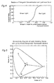
- Figs. 11 and 12 respectively show excitation and emission spectra of YAG:Ce fluorescent material
- Fig. 13 shows an emission spectrum of blue LED covered with a prior art light permeable fluorescent cover with YAG:Ce fluorescent material.
- chip 3 radiates blue light, a part of blue light passes through base material of fluorescent cover 6 to outside without impingement to fluorescent material 7 contained in cover 6, however, another part of blue light hits and excites fluorescent material 7 to emit yellow light after wavelength conversion by fluorescent material 7.
- the blue and yellow lights are optically complementary colors that when mixed are converted into a white light emitted to outside of cover 6.
- This prior art LED for emitting white light has a superior feature of higher mechanical shock resistance, and is advantageous in that it can be operated under less applied voltage, less power consumption, less amount of generated heat, and is eco-friendly without incidental high frequency noise and use of mercury as compared with incandescent lamps, and hot and cold cathode fluorescent tubes of prior art bulb type white light sources.
- a first problem of the device is that it cannot generate a bright luminescent color with degraded chromatic purity when it is used as a white backlighting source for a display, such as a transmission color liquid crystal display which requires sharp emission spectrum.
- a typical backlighting means of a transmission color liquid crystal display includes a cold cathode fluorescent tube of three light wavelengths provided with three light sources disposed away from each other to produce blue, green and red lights with three light emission spectra.
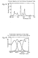
- Fig. 14 shows an example of sharp blue, green and red peaks in emission spectra produced by a typical cold cathode fluorescent tube of three light wavelengths.
- Fig. 15 shows transmission spectra of wide bands through blue, green and red filters to form three primary color pixels in transmission color liquid crystal display.
- transmission spectra of each pixel are essentially determined by corresponding emission spectra of cold cathode fluorescent tube of three wavelengths so that the display can hardly indicate optical colors with high chromatic purity only by transmission property through color filters since the filters merely serve to filter lights in undefined and rough ranges in order to prevent mixture of transmission spectra amoug primary color components, namely, red, green and blue .
- a second problem of the light emitting device is that it produces a light with less amount of red component, and therefore, it cannot perform color indication with satisfactory coloring balance for example in a supplementary light source of reflection color liquid crystal display.
- reflection color liquid crystal indicators in mobile devices such as mobile phones, personal handy phone systems, personal digital assistants and notebook personal computers.
- reflection color liquid crystal display performs coloring indication, utilizing external reflected light such as sunlight irradiated on a surface of the display, however it is disadvantageous in that it cannot be operated in dark area without external light. Therefore, reflection color liquid crystal display requires a supplementary light source (a front light) provided therein for producing a white light to operate it in dark area.
- the light source will produce a light with less amount of red component as shown in Fig. 13, because the light emitting device originally produces an emission spectrum of wider wavelength with less amount of red component as shown in Fig. 12.
- Balance of colorific tone in reflection color liquid crystal display is generally designed based on sunlight spectra obtained as a typical external light source so that the display provides a substantially homogenized color tone on whole display screen under sunlight with much amount of red component.
- prior art light emitting device cannot be used as supplementary light source for the display, because light generated from the device includes less amount of red component, and therefore, when supplementary light source is turned on in dark place, it disadvantageously exhibits reddish color in dark tone with unbalanced color tone on whole display screen compared to external light.
- a third problem of prior art light emitting device is that it makes watcher's eyes tired when he or she keeps watching a display screen of the device because it generates two lights in an optically complementary color relation, specifically blue light given off from LED chip and a yellow light sent out from YAG:Ce fluorescent material 7.
- a report of study on cerebrum physiology indicates that lights in optically complementary color relation, for example a combination of blue and yellow lights form a strong afterimage on viewer's optic nerve and promote asthenopia of his or her eyes when he or she continues watching display screen. Accordingly, it is apparent that eyes would be exhausted by visual activity such as reading for a long time under lights in optically complementary color relation of prior art light emitting device. Then, the third problem would be unavoidable if optically complementary color lights are mixed into a white light as in prior art light emitting device.
- a forth problem of the device arises that it cannot synthesize lights in various color tones by mixing blue and yellow lights from LED chip and YAG:Ce fluorescent material 7 because it generates synthesized lights only in an extremely narrower chromatic range.
- two lights a and h of different wavelengths are indicated respectively as points (xa, ya) and (xb, yb) in a chromaticity diagram.
- a synthesized light is indicated as a point (xm, ym) that lies in a straight line connecting between two points (xa, ya) and (xb, yb)
- position (xm, ym) of synthesized light in chromaticity diagram is determined by relative intensity of two lights a and b .
- position (xm, ym) is plotted in diagram near point (xa, ya) or (xb, yb) depending on whether light a or b is more intensive.
- Fig. 16 shows a locus in standard diagram of a synthesized color provided by prior art light emitting device wherein points P, Q and R represent respectively chromatic locations of blue LED light, a fluorescent light from YAG:Ce and a mixed light.
- This diagram can be directly applied to prior art light emitting device which comprises an LED for producing blue light; and YAG:Ce fluorescent material for converting blue light from LED into yellow light of different wavelength to irradiate a mixed light of blue and yellow lights outside of the device.
- the mixed light is represented by point R that should lie only on a straight line connecting between points P and Q so that the mixed light is restricted in an extremely narrower chromatic range.
- gallium or gadolinium can be doped in fluorescent material 7 to shift output light to a shorter or longer wavelength side.
- an excessive amount or high concentration of doped gallium causes reduction in light emitting efficiency, and an excessive amount or high concentration of doped gadolinium results in promotion of "temperature quenching" that decreases light emitting efficiency with temperature elevation.
- YAG components can be adjusted only in a practically restricted range as the foregoing attempts may bring about deterioration of the important optical features in the device.
- Fig. 17 illustrates a light-emittable chromatic area surrounded by a substantially triangular profile or sector "P-Q 1 -Q 2 -Q-Q 3 -Q 4 -Q 5 -P" that is attained by addition of gallium and gadolinium to YAG components in prior art light emitting device.
- "I” indicates an increase direction of gallium additive amount
- “II” refers to an increase direction of gadolinium additive amount
- a point "C” represents a locus of pure white. In this way, light-emittable chromatic area of prior art device is restricted in narrow sector although specific additives are doped in fluorescent material 7.
- the light permeable fluorescent cover according to the present invention may have the shape in section similar to that of prior art fluorescent cover shown in Figs. 9 and 10.
- LED chip 3 produces blue light with a first peak in a wavelength band of 420 nm to 480 nm.
- Contained in cover 6 according to the present invention is lanthanoid aluminate-manganese fluorescent material 7 excited by blue light from LED chip 3 to emit green and red lights as second and third lights with respectively second and third peaks in wavelength bands 480 nm to 580 nm and 580 nm to 750 nm.
- the fluorescent material 7 contains lanthanoid aluminate-manganese activated by manganese shown by for example one selected from chemical formulae: LaAl 11 O 18 :Mn 2+ and La 2 O 3 11Al 2 O 3 :Mn 2+ .
- the fluorescent cover according to the present invention is characterized by producing blue, green and red lights of independent three primary color emission spectra like a cold cathode fluorescent tube.
- the device according to the present invention indicates three emission spectra in three different emission wavelength bands which comprises blue light of central peak 450 nm irradiated from blue LED, green and red lights of respectively 517 nm and 690 nm converted in wavelength from blue light at and emitted from lanthanoid aluminate-manganese fluorescent material 7.
- Fig. 1 demonstrates emission spectra similar to those of cold cathode fluorescent tube shown in Fig. 14 well in harmonization with transmission spectra of transmission color liquid crystal display shown in Fig. 15.
- Fluorescent material 7 preferably comprises at least one of fluorescent lanthanoid aluminates activated with manganese as shown by at least one selected from chemical formulae: LaAl 11 O 18 :Mn 2+ ; La 2 O 3 11Al 2 O 3 :Mn 2+ ; La 1-x Al 11(2/3)+X O 19 :Mn 2+ X (0.1 ⁇ x ⁇ 0.99); (La, Ce)Al 11 O 19 :Mn 2+ ; and (La, Ce)MgAl 11 O 19 :Mn 2+ .
- Fluorescent cover 6 comprises a base material formed of a plastic material and fluorescent lanthanoid aluminate-manganese powder contained therein.
- plastic material for base material may include one or more resins selected from the group consisting of silicone, polyester, acrylic, epoxy, urethane, nylon, polyamide, polyimide, vinyl chloride, polycarbonate, polyethylene, Teflon, polystyrene, polypropylene and polyolefin.
- fluorescent powder is blended in a plastic melt which is then formed or injected into a shape to attach cover 6 on an encapsulant 5 of an LED by a molding process such as transfer molding or a potting process.
- fluorescent cover 6 may have a suitable elasticity to easily attach it on encapsulant 5, and is effective to keep cover 6 in close and clinging contact to encapsulant 5, preventing cover 6 from coming off encapsulant 5 under external force or vibration applied to cover 6.
- fluorescent cover 6 may be bonded to encapsulant 5 with a light permeable adhesive agent.
- base material may be formed of a thermally shrinkable plastic material to firmly attach cover 6 on encapsulant 5 by thermal shrinkage after heating and cooling cover 6.
- fluorescent cover 6 may be directly formed on encapsulant 5 by spraying plastic melt or dipping LED in plastic melt.
- the fluorescent cover 6 may be formed with entirely flat thickness or partially varied thickness.
- LED chip 3 comprises a substrate or ceramic base plate such as silicon carbide (SiC) or sapphire, and a semiconductor layer of gallium nitride such as GaN, InGaN and InGaAlN formed on substrate by a single crystal or epitaxial growth process.
- the chip 3 is secured on a bottom surface of concavity 1a formed on first conductor 1 by an electrically conductive adhesive, and an electrode on chip 3 is electrically connected through a lead wire 4 to a top of second conductor 2 by a wire bonding process.
- each upper portion of conductors 1 and 2, chip 3 and lead wire 4 are encapsulated or sealed by a light permeable organic resin such as epoxy resin to form a plastic encapsulant 5 of generally cannonball-shape so that chip 3 produces blue light with peak wavelength between 420 nm and 480 nm to outside of encapsulant 5.
- a light permeable organic resin such as epoxy resin
- divalent europium ion Eu 2+ is excited by ultraviolet light to supply excited energy to manganic ion Mn 2+ that irradiates a light
- the inventors have found that, when efficiently excited by irradiation of blue light, La 2 O 2 11Al 2 O 3 :Mn 2+ fluorescent material without europium generates green and red lights in two different emission wavelength bands or ranges by adjusting manganic content.
- Divalent manganic ion (Mn 2+ ) serves as an activator for lanthanoid aluminate-manganese fluorescent material and has property to generate a plurality of emission wavelength bands when a matrix of fluorescent material includes different locations of divalent manganic ion (Mn 2+ ) because emission wavelength of divalent manganic ion (Mn 2+ ) is very susceptible to crystal field size of matrix.
- Lanthanoid aluminate forms a matrix in spinel structure wherein divalent manganic ion (Mn 2+ ) bears four and six coordinations to respectively generate green and red lights with wavelength peaks of 517nm and 690 nm while lanthanoid aluminate is efficiently excited in blue range around 450 nm.
- Figs. 2 and 3 show respectively excitation and emission spectra of lanthanoid aluminate-manganese fluorescent material.
- Emission proportion of green and red lights is determined depending on manganic content.
- Fig. 4 shows emission ratio of green and red lights with varied manganic content ratio in fluorescent material wherein it generates only green light with less than 0.4 manganic content ratio, green and red lights with 0.4 to 0.8 manganic content ratio in transition range and only red light with more than 0.8 manganic content ratio. Accordingly, lights of various luminous colors can selectively be produced in a wider light-emittable green and red areas by adjusting manganic concentration in fluorescent material of lanthanoid aluminate-manganese.
- the fluorescent material 7 includes fluorescent lanthanoid aluminates activated by manganese to produce green and red lights with different manganic concentrations of same components.
- combination of blue LED and lanthanoid aluminate-manganese can attain a light emitting device that produces blue, green and red lights of optical three primary colors in respectively different wavelengths with an adjustable colorific tone, when blue light excites lanthanoid aluminate-manganese to generate green and red lights in simple optical mechanism.
- lanthanoid aluminate means aluminate of lanthanoids i.e. oxides of lanthanoid and aluminum for forming a matrix for fluorescent material.
- LED elements available lanthanoids known as "rare earth elements” contain lantern (La), cerium (Ce), praseodymium (Pr), neodymium (Nd), promethium (Pm), samarium (Sm), europium (Eu), gadolinium (Gd), terbium (Tb), dysprosium (Dy), holmium (Ho), erbium (Er), thulium (Tm), ytterbium (Yb) and lutetium (Lu).
- La litium
- Ce cerium
- Pr praseodymium
- Nd neodymium
- Pm promethium
- Sm samarium
- Eu europium
- Gd gadolinium
- Tb terbium
- Dy dysprosium
- Ho holmium
- Er erbium
- Tm thulium
- Yb ytterbium
- Lu lutetium
- fluorescent matrix may contain an aluminate or aluminates of a single lanthaniod element or plural lanthanoid elements as well as lantern (La) to regulate emission wavelength of green and red lights under controlled wavelength of excitation light for fluorescent material, thereby causing a wide variation of colorific tone in light sent off from LED in embodiments of the present invention.
- activators other than manganese can be added to fluorescent material to improve property to temperature and emission efficiency of LED.
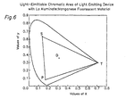
- Fig. 4 shows a chromaticity diagram of lights irradiated from light permeable fluorescent cover according to the present invention when it is attached on LED wherein a synthesized light is contained in an extended area P-T-S-P.
- fluorescent cover according to the present invention is featured that LED capped with the cover can provide a display screen with colorific tone or balance similar to external light by adjusting content ratio of components in fluorescent material 7.
- Lanthanoid aluminate-manganese contained in cover according to the instant invention produces emission spectra that extend over deep red area above 690 nm wavelength as shown in Fig. 3 unlike emission spectra of prior art YAG:Ce fluorescent material as shown in Fig. 12.
- content ratio of emitted green and red lights can be adjusted as required by controlling manganic concentration in lanthanoid aluminate-manganese fluorescent material so that LED can be preferably used as a supplementary light source for reflection color liquid crystal display because it can provide colorific tone or balance similar to external light as sunlight.
- the cover according to the present invention is advantageous in that it does not exhaust watcher's eyes through his or her visual activity for a long time because emission spectra of LED with the cover according to the present invention contain spectra of blue, green and red lights in no optically complementary color relation to each other.
- prior art light emitting device shown in Fig. 13 produces blue and yellow lights in optically complementary color relation to each other that makes watcher's eyes tired.
- a forth feature of LED with the cover according to the present invention is that it can produce mixed color lights in an extremely large area in chromaticity diagram as shown in Fig. 6 with various color tones from combination of blue, green and red lights. It is understood that light-emittable chromatic area P-T-S-P shown in Fig. 6 is much greater than that P-Q 1 to Q 5 -P of prior art light emitting device shown in Fig. 17. Accordingly, the cover of the invention can be preferably applied to show colorful expressions with various colorific tones.
- LED has its directivity of emitted light wherein light intensity is varied depending on a beam spread angle, and in some case, luminous color is disadvantageously irregular between high and low light intensity directions when a light permeable fluorescent cover with an entirely same thickness is attached on LED.
- thickness of cover may be varied along light intensity distribution of LED such that cover is thicker with stronger light intensity area and thinner with weaker light intensity area to provide uniform light color throughout whole irradiation angle.
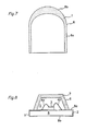
- FIG. 7 shows a second embodiment of light permeable fluorescent cover according to the present invention wherein the cover is applied to LED of cannonball-shaped encapsulant 5 that has a varied light intensity with the strongest light intensity at a top of lens-shaped spherical portion 5b of encapsulant 5 and with continuously decreased light intensity toward cylindrical portion 5a of encapsulant 5.
- the cover has its varied thickness in accordance with change in light intensity of cannonboll-shaped LED such that the cover is thickest at the top portion and continuously thinner toward cylindrical portion 5a of encapsulant 5 to provide uniform light color throughout the irradiation angle.
- Fig. 8 shows a third embodiment of a light permeable fluorescent cover according to the present invention applied to a super small LED for surface-mounted type referred to as a chip LED.
- LED shown in Fig. 8 comprises an insulating base plate 8; a pair of conductors 1, 2 attached to base plate 8 and extending from an upper side 8a to a bottom side 8b of base plate 8; an LED chip 3 as blue LED bonded on an end of conductor 1 by adhesive; a pair of lead wires 4a, 4b connected between electrodes of LED chip 3 and conductors 1, 2; and an encapsulant 5 formed of for example, epoxy resin on the one side 8a of base plate 8 by injection molding for encapsulating LED chip 3, lead wires 4a, 4b and inner ends of conductors 1, 2.
- light permeable cover 6 is bonded on encapsulant 5 by light permeable adhesive because cover 6 does not have the configuration capable of clinging on encapsulant 5 itself.
- the cover 6 may directly be formed on encapsulant 5 by spraying or dipping in plastic melt.
- the light permeable fluorescent cover 6 may be applied to an LED with an LED chip of a light emitting gallium nitride layer on an electrically conductive SiC substrate as shown in Fig. 10 or on an insulating sapphire substrate as shown in Fig. 8.
- the present invention is not limited to the above mentioned materials and structures, and is applicable to LED chips of any structure if light generated from the chip can be converted into two different wavelength areas.
- the cover according to the present invention has the superior functions that can overcome many problems arising in prior art light emitting device with blue LED and YAG:Ce fluorescent material 7.
- the cover of the present invention can be applied to a semiconductor light emitting device, in particular, for emitting white light that has various superior features: higher mechanical shock resistance, operability without high voltage to be applied, less power consumption, less amount of generated heat.
- the cover is very advantageous in that it is eco-friendly without producing incidental high frequency noise or use of mercury as compared with incandescent lamps, and hot and cold cathode fluorescent tubes of prior art bulb type white light sources.
- the light emitting device with the light permeable fluorescent cover according to the present invention is very advantageous since it can adjust at will combined colorific tone of blue light from blue LED, green and red lights from the fluorescent material, keeping a predetermined desired chromatic balance close to external light on display screen.
- the light emitting device can mix three color lights into a white light to be irradiated to outside, it can be preferably used as backlight for transmission color liquid crystal display.
- the light emitting device is very advantageous since it can synthesize lights in a wide chromaticity area by mixing three primary blue, green and red lights to irradiate them to outside in colorful expression.
- the light emitting device does not tire watcher's eyes through his or her visual activity for a long time because generated lights are in no optically complementary color relation to each other, and therefore, it may be preferably utilized as a general light source or supplementary light source for reflection color liquid crystal display, expected to be a solid-state white light source of next generation.
- the light permeable fluorescent cover can be made in simple structure at reduced cost for mass production with good quality.
- the cover may contain a fluorescent material or mixed fluorescent materials for converting red or green light shed from LED into blue and green lights or blue and red lights to provide a synthesized light from three primary color lights.
- the cover may contain a fluorescent material or mixed fluorescent materials for converting a selected first light shed from LED into more than three second, third and fourth lights wherein the first light has a first peak in a first wavelength range; the second light has a second peak in a second wavelength range away from the first peak, the third light has a third peak in a third wavelength range away from the first and second peaks and the fourth light has a fourth peak in a fourth wavelength range away from the first, second and third peaks to synthesize a new light by mixture of the first, second, third and fourth lights.
Applications Claiming Priority (2)
| Application Number | Priority Date | Filing Date | Title |
|---|---|---|---|
| JP2000391457A JP2002190622A (ja) | 2000-12-22 | 2000-12-22 | 発光ダイオード用透光性蛍光カバー |
| JP2000391457 | 2000-12-22 |
Publications (2)
| Publication Number | Publication Date |
|---|---|
| EP1220332A2 true EP1220332A2 (fr) | 2002-07-03 |
| EP1220332A3 EP1220332A3 (fr) | 2005-10-12 |
Family
ID=18857591
Family Applications (1)
| Application Number | Title | Priority Date | Filing Date |
|---|---|---|---|
| EP01130432A Withdrawn EP1220332A3 (fr) | 2000-12-22 | 2001-12-20 | Couvercle fluorescent perméable à la lumière pour diode électroluminescente |
Country Status (5)
| Country | Link |
|---|---|
| US (1) | US7906904B2 (fr) |
| EP (1) | EP1220332A3 (fr) |
| JP (1) | JP2002190622A (fr) |
| KR (1) | KR100587126B1 (fr) |
| TW (1) | TW535304B (fr) |
Cited By (13)
| Publication number | Priority date | Publication date | Assignee | Title |
|---|---|---|---|---|
| EP1403934A2 (fr) * | 2002-09-27 | 2004-03-31 | LumiLeds Lighting U.S., LLC | LED avec un convertisseur de longueur d'onde optique et un filtre optique |
| WO2005062393A2 (fr) * | 2003-12-09 | 2005-07-07 | Cree, Inc. | Dispositifs electroluminescents a semi-conducteurs, embases et procedes de production correspondants |
| DE102005009066A1 (de) * | 2005-02-28 | 2006-09-07 | Osram Opto Semiconductors Gmbh | Verfahren zur Herstellung eines optischen und eines strahlungsemittierenden Bauelementes und optisches sowie strahlungsemittierendes Bauelement |
| US7224000B2 (en) | 2002-08-30 | 2007-05-29 | Lumination, Llc | Light emitting diode component |
| EP2007576A1 (fr) * | 2006-03-15 | 2008-12-31 | KDT Co.Ltd. | Feuille photoluminescente |
| WO2009119038A3 (fr) * | 2008-03-28 | 2009-12-10 | Panasonic Corporation | Produit en résine moulée, source électroluminescente à semi-conducteurs, dispositif d'éclairage et procédé permettant de fabriquer un produit en résine moulée |
| US7800121B2 (en) | 2002-08-30 | 2010-09-21 | Lumination Llc | Light emitting diode component |
| US7888691B2 (en) | 2008-08-29 | 2011-02-15 | Koninklijke Philips Electronics N.V. | Light source including a wavelength-converted semiconductor light emitting device and a filter |
| KR101065238B1 (ko) * | 2002-05-31 | 2011-09-16 | 스미또모 가가꾸 가부시끼가이샤 | 진공 자외선에 의해 여기되는 발광 소자용 형광체 |
| EP2518785A3 (fr) * | 2011-04-27 | 2014-11-05 | Panasonic Corporation | Dispositif électroluminescent et dispositif d'éclairage l'utilisant |
| CN105612240A (zh) * | 2013-10-11 | 2016-05-25 | 普印公司 | 用于ac led照明的平滑磷光体 |
| CN106103650A (zh) * | 2014-03-18 | 2016-11-09 | 宇部兴产株式会社 | 光转换用陶瓷复合材料、其制造方法、及具备其的发光装置 |
| US10340424B2 (en) | 2002-08-30 | 2019-07-02 | GE Lighting Solutions, LLC | Light emitting diode component |
Families Citing this family (49)
| Publication number | Priority date | Publication date | Assignee | Title |
|---|---|---|---|---|
| US7091656B2 (en) | 2001-04-20 | 2006-08-15 | Nichia Corporation | Light emitting device |
| JP4048954B2 (ja) | 2001-04-20 | 2008-02-20 | 日亜化学工業株式会社 | 発光デバイス |
| JP2002374007A (ja) * | 2001-06-15 | 2002-12-26 | Toyoda Gosei Co Ltd | 発光装置 |
| JP2003152227A (ja) * | 2001-11-14 | 2003-05-23 | Citizen Electronics Co Ltd | Ledの色補正手段および色補正方法 |
| KR100497339B1 (ko) * | 2002-01-08 | 2005-06-23 | 주식회사 이츠웰 | 발광 다이오드 장치 및 이를 이용한 조명 기구, 표시 장치그리고 백라이트 장치 |
| TW507853U (en) * | 2002-01-25 | 2002-10-21 | Shi-Huang Lin | Series type lamp |
| JP2004138958A (ja) * | 2002-10-21 | 2004-05-13 | Semiconductor Energy Lab Co Ltd | 表示装置 |
| US7015636B2 (en) * | 2002-10-23 | 2006-03-21 | Charles Bolta | Balanced blue spectrum therapy lighting |
| AU2002952652A0 (en) * | 2002-11-14 | 2002-11-28 | University Of Technology, Sydney | A hybrid lighting system |
| KR20040046516A (ko) * | 2002-11-27 | 2004-06-05 | 이경득 | 조명등 덮개 및 그 제조방법 |
| JP2004228065A (ja) * | 2002-11-29 | 2004-08-12 | Ngk Insulators Ltd | 電子パルス放出装置 |
| JP2004207341A (ja) * | 2002-12-24 | 2004-07-22 | Sanken Electric Co Ltd | 発光波長変換型半導体発光装置及びその製法 |
| JP2004296830A (ja) * | 2003-03-27 | 2004-10-21 | Solidlite Corp | 白色ledの製造方法 |
| US20050006659A1 (en) * | 2003-07-09 | 2005-01-13 | Ng Kee Yean | Light emitting diode utilizing a discrete wavelength-converting layer for color conversion |
| US7029935B2 (en) * | 2003-09-09 | 2006-04-18 | Cree, Inc. | Transmissive optical elements including transparent plastic shell having a phosphor dispersed therein, and methods of fabricating same |
| US20050099808A1 (en) * | 2003-11-12 | 2005-05-12 | Cheng Tzu C. | Light-emitting device |
| WO2005067064A1 (fr) * | 2003-11-25 | 2005-07-21 | Shichao Ge | Del et lampe a del |
| US20050227394A1 (en) * | 2004-04-03 | 2005-10-13 | Bor-Jen Wu | Method for forming die protecting layer |
| US7372198B2 (en) * | 2004-09-23 | 2008-05-13 | Cree, Inc. | Semiconductor light emitting devices including patternable films comprising transparent silicone and phosphor |
| DE102004047727B4 (de) * | 2004-09-30 | 2018-01-18 | Osram Opto Semiconductors Gmbh | Lumineszenzdiodenchip mit einer Konverterschicht und Verfahren zur Herstellung eines Lumineszenzdiodenchips mit einer Konverterschicht |
| ATE398836T1 (de) * | 2004-11-18 | 2008-07-15 | Koninkl Philips Electronics Nv | Lichtemittierende vorrichtung mit umwandlungsstruktur |
| KR100588209B1 (ko) | 2005-01-19 | 2006-06-08 | 엘지전자 주식회사 | 백색 발광 소자 및 그의 제조 방법 |
| US7501659B2 (en) * | 2005-04-12 | 2009-03-10 | Japan Cash Machine Co., Ltd. | LED device and optical detector therewith for bill validator |
| JP4799341B2 (ja) * | 2005-10-14 | 2011-10-26 | 株式会社東芝 | 照明装置 |
| US20070152309A1 (en) * | 2005-12-29 | 2007-07-05 | Para Light Electronics Co., Ltd. | Light emitting diode |
| CN101225931A (zh) * | 2007-01-19 | 2008-07-23 | 童国钧 | 各led灯体照射亮度大致相同的led灯串装置及其实现方法 |
| EP2240831B1 (fr) * | 2008-01-24 | 2015-03-25 | Quad/Graphics, Inc. | Impression a l'aide d'un materiau pouvant changer de couleur |
| US8900921B2 (en) | 2008-12-11 | 2014-12-02 | Stats Chippac, Ltd. | Semiconductor device and method of forming topside and bottom-side interconnect structures around core die with TSV |
| CN102020819A (zh) * | 2009-09-16 | 2011-04-20 | 大连路明发光科技股份有限公司 | 塑料光转换荧光粒料及其应用 |
| US8593040B2 (en) | 2009-10-02 | 2013-11-26 | Ge Lighting Solutions Llc | LED lamp with surface area enhancing fins |
| JP2011192598A (ja) * | 2010-03-16 | 2011-09-29 | Stanley Electric Co Ltd | 白色led光源モジュール |
| US8297767B2 (en) | 2010-09-07 | 2012-10-30 | Xicato, Inc. | LED-based illumination modules with PTFE color converting surfaces |
| TWI447969B (zh) * | 2010-10-20 | 2014-08-01 | Interlight Optotech Corp | 發光二極體封裝結構 |
| US20130228276A1 (en) * | 2010-11-10 | 2013-09-05 | Kuo-Kuang Chang | Method for manufacturing cover plate and method for manufacturing encapsulated light-emitting diode using the cover plate |
| US20120134161A1 (en) * | 2010-11-30 | 2012-05-31 | Nobuo Kawamura | Lighting apparatus |
| CN102544302A (zh) * | 2010-12-17 | 2012-07-04 | 郑榕彬 | 发光二极管液体直接冷却法和使用该方法的发光二极管封装件 |
| CN202371641U (zh) * | 2011-10-14 | 2012-08-08 | 郑榕彬 | 具有双层荧光粉的led灯 |
| JP5751154B2 (ja) * | 2011-12-14 | 2015-07-22 | 豊田合成株式会社 | 発光装置及びその製造方法 |
| US9500355B2 (en) | 2012-05-04 | 2016-11-22 | GE Lighting Solutions, LLC | Lamp with light emitting elements surrounding active cooling device |
| JP5945867B2 (ja) * | 2012-05-11 | 2016-07-05 | パナソニックIpマネジメント株式会社 | 照明装置 |
| JP6853614B2 (ja) * | 2013-03-29 | 2021-03-31 | 株式会社朝日ラバー | Led照明装置、その製造方法及びled照明方法 |
| USD747228S1 (en) * | 2013-11-04 | 2016-01-12 | Fibar Group S.A. | Door/window sensor |
| CA3028775C (fr) * | 2014-03-04 | 2020-01-07 | Novadaq Technologies Inc. | Ouvertures de filtrage spatial et spectral et systemes d'imagerie optique comportant lesdites ouvertures |
| JP6925100B2 (ja) * | 2015-05-21 | 2021-08-25 | 日亜化学工業株式会社 | 発光装置 |
| US10656316B2 (en) | 2015-08-31 | 2020-05-19 | Novadaq Technologies ULC | Polarization dependent filter, system using the same, and associated kits and methods |
| JP6698676B2 (ja) * | 2015-10-20 | 2020-05-27 | 京セラ株式会社 | 屋内用光源および照明装置 |
| CN109140252A (zh) * | 2018-08-27 | 2019-01-04 | 佛山市顺德区蚬华多媒体制品有限公司 | 灯具、led光源及其制造方法 |
| CN111638613A (zh) * | 2019-03-01 | 2020-09-08 | 鸿富锦精密工业(深圳)有限公司 | 显示装置 |
| KR102035972B1 (ko) * | 2019-04-29 | 2019-10-29 | 셀바이오코리아 주식회사 | 광테라피 기능을 갖는 마스크팩 |
Citations (6)
| Publication number | Priority date | Publication date | Assignee | Title |
|---|---|---|---|---|
| GB2039517A (en) * | 1978-11-21 | 1980-08-13 | Philips Nv | Luminescent materials |
| WO1998006793A1 (fr) * | 1996-08-08 | 1998-02-19 | Kabushiki Kaisha Tokyo Kagaku Kenkyusho | Procede de preparation de luminophore a base d'aluminate |
| JP2000022216A (ja) * | 1998-06-26 | 2000-01-21 | Sanken Electric Co Ltd | 蛍光カバーを有する樹脂封止型半導体発光装置 |
| US6066861A (en) * | 1996-09-20 | 2000-05-23 | Siemens Aktiengesellschaft | Wavelength-converting casting composition and its use |
| EP1013740A2 (fr) * | 1998-12-25 | 2000-06-28 | Konica Corporation | Matériau électroluminescent, dispositif électroluminescent et filtre coloré |
| EP1045458A2 (fr) * | 1996-07-29 | 2000-10-18 | Nichia Chemical Industries, Ltd. | Système de source de lumière et dispositif d'affichage |
Family Cites Families (15)
| Publication number | Priority date | Publication date | Assignee | Title |
|---|---|---|---|---|
| JPH04239588A (ja) * | 1991-01-22 | 1992-08-27 | Matsushita Electron Corp | アルミン酸塩蛍光体およびこれを用いた蛍光ランプ |
| SE506845C2 (sv) | 1996-06-28 | 1998-02-16 | Alfa Laval Ab | Plattvärmeväxlare med bälgförsett foder till anslutningsrör |
| JP3434658B2 (ja) * | 1997-01-14 | 2003-08-11 | サンケン電気株式会社 | 半導体発光装置 |
| US6414426B1 (en) * | 1997-02-13 | 2002-07-02 | Matsushita Electric Industrial Co., Ltd. | High-efficiency light source |
| JP2998696B2 (ja) * | 1997-05-17 | 2000-01-11 | 日亜化学工業株式会社 | 発光ダイオード |
| US5962971A (en) * | 1997-08-29 | 1999-10-05 | Chen; Hsing | LED structure with ultraviolet-light emission chip and multilayered resins to generate various colored lights |
| US6340824B1 (en) * | 1997-09-01 | 2002-01-22 | Kabushiki Kaisha Toshiba | Semiconductor light emitting device including a fluorescent material |
| US6252254B1 (en) * | 1998-02-06 | 2001-06-26 | General Electric Company | Light emitting device with phosphor composition |
| US5959316A (en) * | 1998-09-01 | 1999-09-28 | Hewlett-Packard Company | Multiple encapsulation of phosphor-LED devices |
| JP3424566B2 (ja) * | 1998-09-29 | 2003-07-07 | 松下電器産業株式会社 | 蛍光ランプおよび照明器具 |
| JP2000208822A (ja) * | 1999-01-11 | 2000-07-28 | Matsushita Electronics Industry Corp | 半導体発光装置 |
| KR200181326Y1 (ko) * | 1999-12-24 | 2000-05-15 | 서울반도체주식회사 | 색변환 발광다이오드 |
| KR100372834B1 (ko) * | 2000-05-25 | 2003-02-19 | 에이프로시스템즈 (주) | 형광 물질을 이용한 복합 파장의 광을 발생시키는 발광반도체 소자 |
| JP3609709B2 (ja) * | 2000-09-29 | 2005-01-12 | 株式会社シチズン電子 | 発光ダイオード |
| JP2002118292A (ja) | 2000-10-11 | 2002-04-19 | Sanken Electric Co Ltd | 半導体発光装置 |
-
2000
- 2000-12-22 JP JP2000391457A patent/JP2002190622A/ja active Pending
-
2001
- 2001-12-20 EP EP01130432A patent/EP1220332A3/fr not_active Withdrawn
- 2001-12-20 KR KR1020010081578A patent/KR100587126B1/ko not_active IP Right Cessation
- 2001-12-21 US US10/026,871 patent/US7906904B2/en not_active Expired - Fee Related
- 2001-12-21 TW TW090131893A patent/TW535304B/zh not_active IP Right Cessation
Patent Citations (6)
| Publication number | Priority date | Publication date | Assignee | Title |
|---|---|---|---|---|
| GB2039517A (en) * | 1978-11-21 | 1980-08-13 | Philips Nv | Luminescent materials |
| EP1045458A2 (fr) * | 1996-07-29 | 2000-10-18 | Nichia Chemical Industries, Ltd. | Système de source de lumière et dispositif d'affichage |
| WO1998006793A1 (fr) * | 1996-08-08 | 1998-02-19 | Kabushiki Kaisha Tokyo Kagaku Kenkyusho | Procede de preparation de luminophore a base d'aluminate |
| US6066861A (en) * | 1996-09-20 | 2000-05-23 | Siemens Aktiengesellschaft | Wavelength-converting casting composition and its use |
| JP2000022216A (ja) * | 1998-06-26 | 2000-01-21 | Sanken Electric Co Ltd | 蛍光カバーを有する樹脂封止型半導体発光装置 |
| EP1013740A2 (fr) * | 1998-12-25 | 2000-06-28 | Konica Corporation | Matériau électroluminescent, dispositif électroluminescent et filtre coloré |
Non-Patent Citations (1)
| Title |
|---|
| PATENT ABSTRACTS OF JAPAN vol. 2000, no. 04, 31 August 2000 (2000-08-31) & JP 2000 022216 A (SANKEN ELECTRIC CO LTD), 21 January 2000 (2000-01-21) & US 6 472 765 B1 (SANO TAKESHI ET AL) 29 October 2002 (2002-10-29) * |
Cited By (30)
| Publication number | Priority date | Publication date | Assignee | Title |
|---|---|---|---|---|
| KR101065238B1 (ko) * | 2002-05-31 | 2011-09-16 | 스미또모 가가꾸 가부시끼가이샤 | 진공 자외선에 의해 여기되는 발광 소자용 형광체 |
| US7224000B2 (en) | 2002-08-30 | 2007-05-29 | Lumination, Llc | Light emitting diode component |
| US10340424B2 (en) | 2002-08-30 | 2019-07-02 | GE Lighting Solutions, LLC | Light emitting diode component |
| US8436380B2 (en) | 2002-08-30 | 2013-05-07 | GE Lighting Solutions, LLC | Light emitting diode component |
| US8362695B2 (en) | 2002-08-30 | 2013-01-29 | GE Lighting Solutions, LLC | Light emitting diode component |
| US7800121B2 (en) | 2002-08-30 | 2010-09-21 | Lumination Llc | Light emitting diode component |
| US7402840B2 (en) | 2002-09-27 | 2008-07-22 | Philips Lumileds Lighting Company, Llc | Selective filtering of wavelength-converted semiconductor light emitting devices |
| US7026663B2 (en) | 2002-09-27 | 2006-04-11 | Lumileds Lighting U.S., Llc | Selective filtering of wavelength-converted semiconductor light emitting devices |
| EP1403934A3 (fr) * | 2002-09-27 | 2005-07-06 | LumiLeds Lighting U.S., LLC | LED avec un convertisseur de longueur d'onde optique et un filtre optique |
| EP1403934A2 (fr) * | 2002-09-27 | 2004-03-31 | LumiLeds Lighting U.S., LLC | LED avec un convertisseur de longueur d'onde optique et un filtre optique |
| WO2005062393A2 (fr) * | 2003-12-09 | 2005-07-07 | Cree, Inc. | Dispositifs electroluminescents a semi-conducteurs, embases et procedes de production correspondants |
| US8847257B2 (en) | 2003-12-09 | 2014-09-30 | Cree, Inc. | Semiconductor light emitting devices and submounts |
| US7518158B2 (en) | 2003-12-09 | 2009-04-14 | Cree, Inc. | Semiconductor light emitting devices and submounts |
| JP2011193030A (ja) * | 2003-12-09 | 2011-09-29 | Cree Inc | 半導体発光デバイスおよびサブマウント、ならびにそれを形成するための方法 |
| WO2005062393A3 (fr) * | 2003-12-09 | 2006-01-05 | Cree Inc | Dispositifs electroluminescents a semi-conducteurs, embases et procedes de production correspondants |
| US8138000B2 (en) | 2003-12-09 | 2012-03-20 | Cree, Inc. | Methods for forming semiconductor light emitting devices and submounts |
| US8247263B2 (en) | 2005-02-28 | 2012-08-21 | Osram Opto Semiconductors Gmbh | Method for producing an optical, radiation-emitting component and optical, radiation-emitting component |
| DE102005009066A1 (de) * | 2005-02-28 | 2006-09-07 | Osram Opto Semiconductors Gmbh | Verfahren zur Herstellung eines optischen und eines strahlungsemittierenden Bauelementes und optisches sowie strahlungsemittierendes Bauelement |
| EP2007576A4 (fr) * | 2006-03-15 | 2011-11-16 | Lg Innotek Co Ltd | Feuille photoluminescente |
| US8237352B2 (en) | 2006-03-15 | 2012-08-07 | Lg Innotek Co., Ltd. | Photoluminescent sheet |
| US8723411B2 (en) | 2006-03-15 | 2014-05-13 | Lg Innotek Co., Ltd. | Photoluminescent sheet |
| EP2007576A1 (fr) * | 2006-03-15 | 2008-12-31 | KDT Co.Ltd. | Feuille photoluminescente |
| CN101946337B (zh) * | 2008-03-28 | 2012-12-05 | 松下电器产业株式会社 | 模制树脂产品、半导体发光源、照明装置以及模制树脂产品制造方法 |
| WO2009119038A3 (fr) * | 2008-03-28 | 2009-12-10 | Panasonic Corporation | Produit en résine moulée, source électroluminescente à semi-conducteurs, dispositif d'éclairage et procédé permettant de fabriquer un produit en résine moulée |
| US8890186B2 (en) | 2008-03-28 | 2014-11-18 | Panasonic Corporation | Molded resin product, semiconductor light-emitting source, lighting device, and method for manufacturing molded resin product |
| US8114692B2 (en) | 2008-08-29 | 2012-02-14 | Philips Lumileds Lighting Company, Llc | Light source including a wavelength-converted semiconductor light emitting device and a filter |
| US7888691B2 (en) | 2008-08-29 | 2011-02-15 | Koninklijke Philips Electronics N.V. | Light source including a wavelength-converted semiconductor light emitting device and a filter |
| EP2518785A3 (fr) * | 2011-04-27 | 2014-11-05 | Panasonic Corporation | Dispositif électroluminescent et dispositif d'éclairage l'utilisant |
| CN105612240A (zh) * | 2013-10-11 | 2016-05-25 | 普印公司 | 用于ac led照明的平滑磷光体 |
| CN106103650A (zh) * | 2014-03-18 | 2016-11-09 | 宇部兴产株式会社 | 光转换用陶瓷复合材料、其制造方法、及具备其的发光装置 |
Also Published As
| Publication number | Publication date |
|---|---|
| US20020080501A1 (en) | 2002-06-27 |
| US7906904B2 (en) | 2011-03-15 |
| KR100587126B1 (ko) | 2006-06-07 |
| EP1220332A3 (fr) | 2005-10-12 |
| KR20020051845A (ko) | 2002-06-29 |
| JP2002190622A (ja) | 2002-07-05 |
| TW535304B (en) | 2003-06-01 |
Similar Documents
| Publication | Publication Date | Title |
|---|---|---|
| US7906904B2 (en) | Light permeable fluorescent cover for light emitting diode | |
| KR100645403B1 (ko) | 백색 발광 장치 | |
| US7531956B2 (en) | Light emitting device and phosphor for the same | |
| EP1802728B1 (fr) | Phosphore et dispositif d'emission de lumiere l'utilisant | |
| US6614170B2 (en) | Light emitting diode with light conversion using scattering optical media | |
| JP5177317B2 (ja) | 発光装置と表示装置 | |
| US7753553B2 (en) | Illumination system comprising color deficiency compensating luminescent material | |
| US7858997B2 (en) | Light emitting apparatus and light emitting method | |
| JP3246386B2 (ja) | 発光ダイオード及び発光ダイオード用の色変換モールド部材 | |
| US20030038295A1 (en) | Light emitting device with fluorescent member excited by semiconductor light emitting element | |
| JP2002141559A (ja) | 発光半導体チップ組立体及び発光半導体リードフレーム | |
| JP2003179259A6 (ja) | 発光装置と表示装置 | |
| JP2002134795A (ja) | 半導体発光装置及びその製法 | |
| KR20050089490A (ko) | 자색 발광 다이오드 광원을 이용한 백색 발광 다이오드 | |
| JP2007059667A (ja) | 発光装置 | |
| KR100605212B1 (ko) | 형광체 및 이를 이용한 백색 발광다이오드 | |
| KR100527921B1 (ko) | 백색 반도체 발광장치 | |
| KR100567550B1 (ko) | 핑크색 발광 다이오드 및 그 제조 방법 | |
| KR20030093369A (ko) | 백색 발광 다이오드 및 그 제작 방법 |
Legal Events
| Date | Code | Title | Description |
|---|---|---|---|
| PUAI | Public reference made under article 153(3) epc to a published international application that has entered the european phase |
Free format text: ORIGINAL CODE: 0009012 |
|
| AK | Designated contracting states |
Kind code of ref document: A2 Designated state(s): AT BE CH CY DE DK ES FI FR GB GR IE IT LI LU MC NL PT SE TR |
|
| AX | Request for extension of the european patent |
Free format text: AL;LT;LV;MK;RO;SI |
|
| PUAL | Search report despatched |
Free format text: ORIGINAL CODE: 0009013 |
|
| AK | Designated contracting states |
Kind code of ref document: A3 Designated state(s): AT BE CH CY DE DK ES FI FR GB GR IE IT LI LU MC NL PT SE TR |
|
| AX | Request for extension of the european patent |
Extension state: AL LT LV MK RO SI |
|
| AKX | Designation fees paid |
Designated state(s): DE NL SE |
|
| STAA | Information on the status of an ep patent application or granted ep patent |
Free format text: STATUS: THE APPLICATION IS DEEMED TO BE WITHDRAWN |
|
| 18D | Application deemed to be withdrawn |
Effective date: 20060413 |