EP1214902A2 - Düse für einen Staubsauger - Google Patents
Düse für einen Staubsauger Download PDFInfo
- Publication number
- EP1214902A2 EP1214902A2 EP01129197A EP01129197A EP1214902A2 EP 1214902 A2 EP1214902 A2 EP 1214902A2 EP 01129197 A EP01129197 A EP 01129197A EP 01129197 A EP01129197 A EP 01129197A EP 1214902 A2 EP1214902 A2 EP 1214902A2
- Authority
- EP
- European Patent Office
- Prior art keywords
- nozzle
- nozzle head
- head
- suction
- spring
- Prior art date
- Legal status (The legal status is an assumption and is not a legal conclusion. Google has not performed a legal analysis and makes no representation as to the accuracy of the status listed.)
- Granted
Links
Images


Classifications
-
- A—HUMAN NECESSITIES
- A47—FURNITURE; DOMESTIC ARTICLES OR APPLIANCES; COFFEE MILLS; SPICE MILLS; SUCTION CLEANERS IN GENERAL
- A47L—DOMESTIC WASHING OR CLEANING; SUCTION CLEANERS IN GENERAL
- A47L9/00—Details or accessories of suction cleaners, e.g. mechanical means for controlling the suction or for effecting pulsating action; Storing devices specially adapted to suction cleaners or parts thereof; Carrying-vehicles specially adapted for suction cleaners
- A47L9/02—Nozzles
Definitions
- the invention relates to a nozzle for a vacuum cleaner, especially hard floor nozzle, with one on the floor seated nozzle head and one with the nozzle head a vacuum cleaner connecting nozzle body, wherein a connector is formed on the nozzle body and the nozzle as a whole with rollers or over sliding surfaces is movable and a suction channel is provided is, that of the connecting piece through the Extending nozzle body, opens into the nozzle head.
- Nozzles for vacuum cleaners of the type in question are known.
- These known nozzles have been found to be particularly useful vacuuming in niches, vacuuming around objects, e.g. chair or table legs, as well as vacuuming along baseboards or the like as problematic. This is only a laborious one for the user Handling of the vacuum cleaner enables. So is a satisfactory suction along skirting boards usually only achievable if the Nozzle with its front edge across the usual, through the Castors predetermined suction direction along the baseboard is moved. This transverse movement is for the user associated with increased effort.
- Vacuuming niches whose opening dimensions are essential is smaller than the nozzle width, is with the known No nozzles possible. This may be a Exchange of the nozzle for a crevice nozzle or the like necessary.
- So pivots, for example, along the nozzle head for edge extraction of baseboards in a position in which the Front edge of the nozzle head parallel to the baseboard is aligned and at an angle, for example. perpendicular for the usual suction or displacement direction of the vacuum cleaner, runs along this skirting board.
- the nozzle body remains in its usual direction of suction or displacement, so that an edge suction by means of the swiveled nozzle head through the further in the direction of displacement aligned rollers of the nozzle body no additional effort for the user means. It is preferred here that the nozzle head automatically in the event of a collision with an object, such as a baseboard or a chair leg, relative pivoted to the nozzle body. So is in the simplest Wise suction around objects, such as.
- the pivotability over a Hinge is formed with a vertical hinge axis. This joint is penetrated by that, by that Connection piece extending through the nozzle body Suction channel, with further nozzle head side of the joint preferably the suction channel mouth is formed in the nozzle head is. In this regard, it is further proposed that that the nozzle head in a horizontal plane is pivotable.
- the nozzle head is in the pivoted state partially extends below the nozzle body. according to the nozzle head dips in the pivoted state at least with a partial area in one of the nozzle body covered area.
- the swiveling of the Nozzle under the nozzle body allowing free space is further selected so that at least one pivoting of the nozzle head to the original normal position is the largest width of the nozzle in the area of the fixed nozzle body by pivoting of the nozzle head is undershot.
- the nozzle head be in the normal position a larger width (i.e. extension across to Travel direction) as depth (extension in travel direction) having.
- a large width of the nozzle head is desired for vacuuming large areas.
- the shallow depth of the nozzle head creates a desire encountered what depth in a 90 ° pivoted State of the nozzle head the width of the same in this Position. So it is preferred that the width of the Nozzle head more than twice the greatest depth of the nozzle head.
- the depth of the nozzle head across the width of the nozzle head is. So it turns out to be particularly beneficial if the nozzle head has a circular segment-like layout having. Accordingly, a straight line, in Normal position extending transversely to the direction of travel Given leading edge, with a rear Edge through one, the ends of the straight front edge connecting circular arc line is formed. This Rounding the nozzle head proves to be handling-related advantageous, especially when unscrewing of the nozzle head from narrow niches, being further due to the narrow design viewed in the depth direction of the nozzle head also the suction depth in Niches is improved. It is advantageous further provided that the joint in the area of the largest Depth of the nozzle head is formed.
- the Nozzle head relative to the nozzle body by 360 ° and more is pivotable. Accordingly, the nozzle head is preferred can be rotated as required, even after a 360 ° rotation to return to its original normal position. It is further suggested that one or more Preferred swivel positions of the nozzle head locked are, for example. spring-supported locking lugs, sliding or Roll body in appropriately designed recesses can kick.
- the nozzle head in one, based on the normal position, at which the straight front edge perpendicular to the usual Direction of travel is aligned, 90 ° or 270 ° position locked in which locked position the Nozzle head is pivoted in such a way that it is related to the width - shallow depth in the direction of travel points, for example for vacuuming niches.
- the 0 ° and 180 ° positions are locked, in which positions the nozzle head is aligned so that its Width extension transverse to the direction of travel, d. H. is aligned in the normal position.
- more than two To design pivoted positions latched for example. four positions offset by 90 ° to each other.
- the nozzle head is preferred from each other intermediate position, i.e. also from the 90 ° to Normal position swiveled working position, always spring-assisted again automatically in the normal position moved back.
- the proposed spring support can also by an appropriate Material elasticity in the area of the joint his.
- a spring in Form of an elongated element is provided, which runs across the suction channel in the Nozzle head extends.
- an elongated one Spring steel can be arranged in the nozzle head, which acts on it in such a way that a deflection spring torque built up the reset the nozzle head in the normal position. This normal position of the nozzle head is defined due to the undeflected, elongated orientation of the Spring element.
- the intended spring is held in the nozzle head and on the one that penetrates the nozzle head Suction channel of the nozzle body acts. So it goes on suggested that the spring penetrate the suction channel.
- the suction channel wall is for this purpose with radially aligned openings for the throughput of the spring or with appropriately aligned Provide grooves for receiving spring sections, so that a deflection of the nozzle head relative to the nozzle body is bent out on both sides over the Extending suction channel wall and in the nozzle head held spring sections causes.
- the training can also be chosen in this way be that the spring is connected to the suction channel, wherein the spring further preferably the suction channel not enforced. Rather, there is a free end here the spring in the area of the suction channel wall, so For example, in an appropriately aligned hole or Groove. It is also conceivable that the free spring end in the course of Production around the suction channel wall. Also there is a possibility that the spring will wall the Suction channel interspersed secant, although conceivable is that the spring is on both sides of the secant Throughput through the suction channel wall or just extends unilaterally to this.
- the spring over part of the wall of the suction channel in the circumferential direction is adapted to this. So one can on the Suction channel wall acting spring section in a Insert the annular section-shaped groove of the wall.
- there is an alternative extrusion coating of the spring section in the course of the production of the suction channel wall conceivable.
- outside the Suction channel opposite abutment for the spring are formed in the nozzle head.
- guide pins arranged on both sides of the spring or the like may be provided.
- the spring in the area of an outer boundary Shaping for the spring in the deflected state Recess is held.
- the leaf spring has a curved cross section. So it can Leaf spring made from a profiled sheet of metal or steel be shaped. In this regard, one is preferred Leaf spring with a spherical bulge. So can such a leaf spring perpendicular to the longitudinal direction in be curved in the plane of the profile. Profiled by this -bombieri- leaf spring also turns the Nozzle head always back to an exact zero position and provides a stable zero position, similar to a detent As a result of the above solutions is at low number of parts a regressive torque generation given implicit zero position detent.
- the nozzle head on the bottom has one or more bristle sections which Bristle sections in particular to limit the suction space serve with hard floor nozzles.
- a Height of the nozzle head based on the free vertical extension a bristle of a bristle section, including the bristles two to five times that corresponds to the free vertical length of the bristle.
- the width of the nozzle body in the area of the nozzle head one third up to a fifth of the width of the nozzle head, for example with a nozzle head width of 300 mm about 60 mm. It is further preferred that the nozzle head in width towards the casters expanded, further proposed in this regard will that the width of the nozzle body in the range of Rollers or the sliding surfaces about half of the Corresponds to the width of the nozzle head. Also in this Roller area is the width of the nozzle body so chosen that an overall slim design in particular reached to allow suction in niches is.
- the width of the nozzle body in the area the rollers or the sliding surfaces about the corresponds to the greatest depth of the nozzle head.
- the nozzle body is between the nozzle head and the rollers or sliding surfaces like a bridge extends, here the height of the bridge section corresponds approximately to the height of the nozzle head.
- the bridge have a bridge clearance at the bottom leaves and that the length of the bridge clearance - viewed in the direction of displacement - more than that Half of the width of the nozzle head corresponds to what the desired pivotability by 360 ° and more Nozzle head is guaranteed.
- connection piece in a first swivel joint pivotable about an axis transverse to the direction of travel of the nozzle is.
- the over the connecting piece with the vacuum cleaner connected to the nozzle regardless of the swivel position of the nozzle head total flattened to about vacuum under furniture.
- the connecting piece continues a second Has swivel joint with a deviation from extending the central axis of the connecting piece Pivot axis.
- the first Swivel joint has a locked secure preferred position, the detent not by weight the nozzle can be lifted.
- a lift-off position of the nozzle by swinging it open given the same about the roller axis to larger To be able to record dirt particles, which otherwise would be pushed in front of the nozzle.
- this locking of the withdrawal position emphasized will canceled. All of the above features are both in Connection with hard floor nozzles as well as with nozzles Carpet extraction, if necessary with rotating brush rollers, significant.
- an auxiliary air path in a swivel position is open. It is further preferred that when the nozzle head is pivoted through an angle > 0 °, d. H. from the normal operating position of the Nozzle head transversely to the direction of travel, a secondary air path is opened.
- the latter can be in the range of Swivel joint or in the area of other components be trained. With a swivel angle of 0 ° (normal operating position) no secondary air flows in, so that the full suction power is available here stands.
- This solution is not only for passive carpet nozzles, but also with carpet nozzles with rotating Brush rollers applicable.
- the Opening the suction channel to the second corner area in Dependence on the swivel angle is reduced while the opening in relation to the first corner area is unaffected.
- the reduction of the suction channel opening the second corner area can be up to one Lead the suction channel to this corner area. After that, the full suction power is in the first Corner area.
- Closure of the suction channel in relation to a corner area by reducing the cross section between a front wall of the front edge corresponding to the Nozzle head and a vertical suction duct wall section he follows.
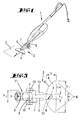
- a vacuum cleaner 1 with a nozzle 2 for processing a floor 3.
- the nozzle 2 is a hard floor nozzle.
- the features described below this nozzle 2 are, however, also in the case of nozzles with rotating Brushes for carpet cleaning conceivable.
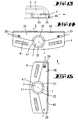
- the nozzle 2 essentially consists of one the bottom 3 seated nozzle head 4 and one Nozzle head 4 connecting with the vacuum cleaner 1 Nozzle body 5 together, being on the nozzle body 5
- Connection piece 6 is designed to connect the Nozzle 2 to the vacuum cleaner 1. Through the nozzle body 5 extends, starting from the connecting piece 6, a suction channel 7, which opens into the nozzle head 4.
- the suction mouth is provided with the reference number 8.
- the connector 6 is on the top in the area of a End of the nozzle body 5 arranged such that the Connection piece 6 in a first swivel joint 9 around an axis x transverse to the direction of travel r of the nozzle 2 is pivotable. On this pivot axis x are also Arranged rollers 10, over which the nozzle body 5 supported on the floor 3 at one end.
- connection piece 6 has a second one Swivel joint 11 on, with a different from the Center axis a of the connecting piece 6 extending Swivel axis y.
- the nozzle body 5 extends between the nozzle head 4 and the rollers 10 bridge-like, the Nozzle body 5 in its transverse direction r measured width - starting from the area of the rollers 10 tapers to the end facing away from it.
- the nozzle head 4 is vertical Axis z pivotable in a horizontal plane.
- the joint 12 is formed so that it can be pivoted the nozzle head 4 by 360 ° and more, d. H. a given complete free pivotability of the same is.
- the nozzle head 4 extends partially below of the boom 13 designed as a bridge Nozzle body 5. In the course of pivoting the Nozzle head 4 passes through this one under the Bridge 13 formed bridge clearance 29, the in Direction of travel r measured length 1 more than half corresponds to the width b1 of the nozzle head 4, whereby the nozzle head width b1 to the extent transverse to Direction of travel r in the normal position according to FIG. 3 refers.
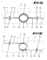
- the nozzle head 4 has a circular segment-like plan on, with a in the normal position according to FIG. 3 in Travel direction r front, transverse to travel direction r extending rectilinear end edge 14 and one rear, connecting the ends of the front edge 14, in the outline of a circular section edge 15.
- a circle diameter is selected, the Center point M lies outside the nozzle head 4.
- nozzle head width b1 is a ratio of nozzle head width b1 to maximum depth t of the nozzle head 4 selected from 3: 1. Accordingly, the nozzle head 4 in an exemplary Width b1 of 300 mm a greatest depth t of 100 mm.
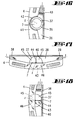
- the bottom of the nozzle head 4 is in a known manner several, four in the illustrated embodiment Bristle sections 16 to limit the suction space provided, the bristles of a free vertical extension h1 of 10 mm, for example (see FIG. 6).
- the height h2 of the nozzle head 4 including the bristle sections 16 corresponds in the illustrated embodiment about three times the free vertical extent h1 of the bristle sections 16.
- Nozzle body 5 points in the area of its bridge 13 a height h3, which is about two-thirds of the Height h2 of the nozzle head 4 corresponds.
- the joint is 12 between nozzle head 4 and nozzle body 5 in the area the greatest depth of the nozzle head 4, wherein the width b2 of the nozzle body 5 or its bridge 13 in the area of the nozzle head 4 or the joint 12, for example corresponds to a fifth of the width b1 of the nozzle head 4.
- the in the direction of the rollers 10th has widening nozzle body 5 in the area of Rollers 10 have a width b3, which is about a third corresponds to the width b1 of the nozzle head 4.
- this nozzle body width b3 corresponds approximately to that greatest depth t of the nozzle head 4, so accordingly also approx. 100 mm.
- the nozzle head 4 according to that in the representations 1 to 8
- the first embodiment shown is in four preferred pivot positions rested. On the one hand in the Fig. 4 shown normal position (0 ° position) Surface treatment. On the other hand in a 180 ° pivoted position, in which the in the floor plan Edge section 15 in the form of a circular section in the direction of travel is in front. The 90 ° and the 270 ° positions locked, in which the nozzle head 4 with its narrow depth t transverse to the direction of travel has.
- This locking is realized by the underside of the nozzle head 4 two in the direction of the vertical Joint axis z acting, supported by compression springs 17 Locking elements 18 on one, four at 90 ° angular intervals interlocking recesses 19 having locking plate 20 act.
- the latter is non-rotatably connected to the nozzle body 5.
- the locking plate 20 also has an elliptical floor plan on, according to which after swiveling the Nozzle head 4 spring-supported in an intermediate position a next home or rest position is found.
- the Allows nozzle head 4 for sucking around an object 30, which the latter is a swiveling of the nozzle head 4 causes about the pivot axis z. 5 is one such position of the nozzle head 4 pivoted through 90 ° shown, this position also secured is.
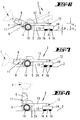
- FIG. 6 to 8 are also three pivot positions of the connecting piece 6 shown. That about this serving first swivel joint 9 has a non-detent 6 preferred position, which locking device not by the weight of the nozzle 2, but can only be overridden by the user. In in this preferred locked position is the nozzle 2, For example, to record larger, otherwise only before Nozzle 2 pushed dirt particles around the pivot axis or roller axle x can be raised (see dash-dot line Representation in Fig. 6).
- the connecting piece 6 also further can be pivoted downwards about the swivel axis x around the Push vacuum cleaner 1 as a whole flat can.
- two can be provided via compression springs 17 thrust pieces acting in the direction of the hinge axis z 21 act on the elliptical contour of the locking plate 20, whereupon by the elliptical shape of the Locking plate 20 automatically after the loss of support of the nozzle head 4 on an object 30 the normal position 9 is taken.
- These locking lugs 23 dive into correspondingly shaped recesses 19 of the locking plate 20, which is elliptically shaped in plan a, contrary to the illustrated embodiment with two, the normal position and the 180 ° position rest locking recesses 19 and more Locking recesses 19 for locking, for example the 90 ° and 270 ° position can be provided.
- tension springs 24, which are at one end on the locking plate 20 and at the other end on the underside of the nozzle head 4 are connected to obtain one automatic reset of the nozzle head 4 in the Serve normal position.
- Fig. 12 a solution is shown in which spring-elastic arms 25, which underside of the nozzle head 4 are connected with their free ends, which Form locking lugs 23, act on locking plate 20.
- the free ends of the resilient arms 25 also on Axle bodies 60 bear mounted roller body 61 for latching interaction with recesses 19 of the Rasttellers 20.
- the arrangement of is also conceivable Sliding bodies.
- the nozzle head 4 can be fastened to the bridge 13 so that it can be tilted by two horizontally oriented tilting axes h 1 and h 2 offset from one another by 90 °.
- the nozzle head 4 can therefore adapt to the unevenness of the floor via the two cardanically arranged axes h 1 and h 2 , which leads to an improved cleaning result.
- the illustrated and described embodiments with regard to securing the rest or resetting the Nozzle head 4 are preferably in a hidden position arranged within the nozzle head 4.
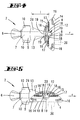
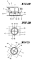
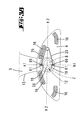
- FIG. 13 to 15 show in a further embodiment a nozzle 2 according to the invention, in which the Suction channel 7 with an approximately semicircular in cross section Suction channel end section 35 in the area of Suction mouth 36 of the nozzle head 4 protrudes.
- the suction mouth 36 extends symmetrically from the suction channel mouth 37 in both corner areas 38 and 39 of the nozzle head 4, the suction channel mouth 37 on the front by a along the front wall of the Nozzle head 4 extending bristle strip 40 and rearward is limited by the nozzle head housing 41.
- the suction channel 7 ends in the area of the suction channel end section 35 in the nozzle head 4 such that the suction mouth 36 flows symmetrically from the intake air 1 becomes.
- closed and open Suction mouth area is by the distance of the turning center, d. H. the z axis, from the front edge of the suction mouth (bristle strip 40) adjustable.
- each can part of the suction mouth 36 swiveled back, for example 50% be isolated from the volume flow.
- Suction channel end section 35 essentially from one closed, semicircular area 43 and two, through a right angle to the front edge of the nozzle head, d. H. perpendicular to the bristle strip 40, extending Partitions 44 penetrate areas 45 which quarter-circular open areas 45 in the suction mouth 36 flow out.
- a base plate 46 of the nozzle head 4 over the closed Area 43 of the suction channel end section 35.
- the open areas 45 of the suction channel end section 35 allow a symmetrical flow through the suction mouth 36 to, the latter through the partition 44 in two is divided into equal sections.
- FIG. 19 to 21 an alternative embodiment according to FIG. 19 to 21 are provided, in which means are provided are dependent on influencing the suction air flow from a pivoting position of the nozzle head 4.
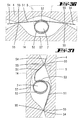
- the Nozzle head 4 in the joint area into the suction channel end section 35 of the nozzle body 5 projecting neck 47, which with one or two radially aligned holes 48 is provided.
- neck 47 Section of the suction channel end section 35 this is arranged with the bore 48 on both sides Elongated holes 49 provided.
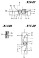
- a spring 51 shaped in this way extends in a straight line, parallel to the front edge 14 of the nozzle head 4 and passes through the suction channel 7.
- the suction channel wall 52 is diametrical with two opposite, radially aligned grooves 53 provided which in the basic position of the nozzle head 4th 22 aligned parallel to the end edge 14 are. In the area of these grooves 53 it asserts itself on both sides of the suction channel 7 extending uniformly Spring 51, wall 52 and suction channel 7.
- abutments 55 shaped in the form of guide pins, where specifically on both sides of the suction channel 7 each a pair of abutments 55 are arranged.
- the Distance between two abutments 55 of a pair here slightly larger than that measured in the same direction Thickness of the spring 51, so the latter in this regard is freely movable in the area of its free ends 54.
- the spring 51 in particular the leaf spring, from its elongated resting position, due to the lateral support of the free ends 54 on the abutments 55, deflected, with which a driving torque is achieved (see Fig. 24).
- the spring 51 By designing the spring 51 as a leaf spring with a curved cross-section is not just the hysteresis behavior improved by the basic position. moreover the nozzle head always turns to an exact one Zero position - basic position - back. This also means a, zero position similar to a detent reachable.
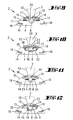
- FIGS. 25 and 26 Another embodiment with a in the basic position straight spring 51 is shown in FIGS. 25 and 26. Contrary to the previously described embodiment however, does not penetrate the spring 51 the suction channel 7, but penetrates the wall 52 of the Suction channel 7 secant in the area of a corresponding aligned groove 53. Alternatively, the Section 52 penetrating section of the spring 51 also in the Injection molded during the manufacture of the suction channel wall 52 his.
- FIG. 28 shows the deflected one Position of the nozzle head 4, in which the springs 51 outside the integration in the suction duct wall 52 restoring torque are deflected.
- the spring 51 protrudes at both ends of the loop with parallel to the front edge 14 of the nozzle head 4 extending free ends 54, which free Ends 54 here also between two abutments 55 are led.
- an arrangement of two springs 51 can be provided, which are symmetrical are aligned with each other (see Fig. 31).
- the Extend ends 54 of the springs 51 projecting on both sides here parallel to one another and in a side-by-side arrangement lying also parallel to the front edge 14.
- FIG. 32 A configuration in this regard is shown in FIG. 32.
- Springs 51 are provided, their, the suction channel 7 facing Ends in secant-like grooves 53 or accordingly aligned holes.
- springs 51 with diametrically opposite one another, ends associated with wall 52 as shown in FIG. 33 be provided.
- ends associated with wall 52 as shown in FIG. 33 be provided.
- These springs 51 also run in the relaxed basic position parallel to the front edge 14 the nozzle head 4.
- Fig. 36 shows an embodiment in which the abutment 55 are formed by marginal edges a recess formed in the plane of the spring 51 57 of the nozzle head 4.
- the edges of this Recess 57 form an outer boundary for the Spring 51 in the deflected state, the edge of the recess symmetrical to one perpendicular to the face 14 extending axis of symmetry arranged the Cover the area of the suction duct wall 52.
- the outer limit of the recess 57 is also the characteristic curve the spring 51 can be influenced.
- the presented embodiments of the invention are not only for passive carpet nozzles, but also for Carpet nozzles with rotating brush rollers can be used.
- the fixed part (nozzle body 5) of the nozzle 2 Integrated electric motor that works directly via a gearbox or via a power transmission using a toothed belt or integrated in the nozzle head 4 drives a brush roller.
- a drive via a turbine is also conceivable, which is driven by the air flow.
- the power supply is carried out by means of lines running over slip rings or other suitable elements in the movable Part (nozzle head 4) are inserted.
- the object of the invention both alone and in Combination with one of the features described above Significance is also a nozzle in which the Width b1 of the nozzle head 4 more than twice that maximum depth t of the nozzle head 4.
- the object of the invention both alone and in Combination with one of the features described above Significance is also a nozzle in which the Depth t of the nozzle head 4 across the width b1 of the nozzle head 4 is different.
- the object of the invention is also a nozzle in which the Nozzle head 4 relative to the nozzle body 5 by 360 ° and is more pivotable.
- Significance is also a nozzle, in which one Spring 51 is provided in the form of an elongated element which is transverse to the suction channel 7 extends in the nozzle head 4.
- the object of the invention both alone and in Combination with one of the features described above Significance is also a nozzle in which the Spring 51 the wall 52 of the suction channel 7 secant interspersed.
- the object of the invention is also a nozzle in which the Spring 51 over part of the wall 52 of the suction channel 7 is adapted to this in the circumferential direction.
- the object of the invention both alone and in Combination with one of the features described above Significance is also a nozzle in which the Nozzle body 5 on the one hand on the nozzle head 4 and other, on the nozzle body 5 attached rollers 10 or sliding surfaces is supported.
- the object of the invention is also a nozzle in which the Nozzle body 5 in the area of the nozzle head 4 a width b2, which is a fraction of the width b1 of the Nozzle head 4 corresponds.
- the object of the invention is also a nozzle in which the Width b2 of the nozzle body 5 in the area of the nozzle head 4 one third to one fifth of the width b1 of the Nozzle head 4 corresponds.
- the object of the invention is also a nozzle in which the Width b3 of the nozzle body 5 in the area of the rollers 10 or the sliding surfaces about half the width b1 of the nozzle head 4 corresponds.
- the object of the invention is also a nozzle in which the Width b3 of the nozzle body 5 in the area of the rollers 10 or the sliding surfaces about the greatest depth t of Nozzle head 4 corresponds.
- the object of the invention is also a nozzle in which the Bridge 13 leaves a bridge clearance 29 on the bottom side and that the length 1 of the bridge clearance 29 is more than corresponds to half the width b1 of the nozzle head 4.
- Significance is also a nozzle in which the Connection piece 6 in a first swivel joint 9 around an axis x transverse to the direction of travel r of the nozzle 2 is pivotable.
- Significance is also a nozzle in which the Connection piece 6 further a second swivel joint 11 has, with a deviating from the central axis a of the connecting piece 6 extending pivot axis y.
- Significance is also a nozzle, in which in a Pivotal position an auxiliary air path is open.
- the object of the invention is also a nozzle, in which in a Swivel position of the suction air flow 1 with respect to a first corner region 38 of the nozzle head 4 is reinforced.
- the object of the invention is also a nozzle, in which in a Swivel position of the suction air flow 1 with respect to a second corner region 39 of the nozzle head 4 is reduced.
- Significance is also a nozzle in which the Opening of the suction channel 7 to the second corner area 39 is reduced depending on the swivel angle, while opening with respect to the first corner area 38 is unaffected.
- the object of the invention is also a nozzle, in which in the Nozzle head 4 has a partition which extends at right angles 44 is provided and that the closure of the Suction channel 7 by reducing the distance between a vertical suction duct wall and the partition 44 takes place.
- the invention which is important both alone and in combination with one of the features described above, also relates to a nozzle in which the nozzle head 4 is movable about at least one tilt axis h 1 , h 2 oriented transversely to the vertical articulation axis z.
- the subject of the invention which is important both alone and in combination with one of the features described above, is also a nozzle in which the nozzle head 4 can be moved by two horizontally oriented tilting axes h 1 , h 2 arranged offset by 90 ° to one another.
Landscapes
- Engineering & Computer Science (AREA)
- Mechanical Engineering (AREA)
- Nozzles For Electric Vacuum Cleaners (AREA)
- Supply And Installment Of Electrical Components (AREA)
- Electrical Discharge Machining, Electrochemical Machining, And Combined Machining (AREA)
- Jet Pumps And Other Pumps (AREA)
Abstract
Description
- Fig. 1
- eine perspektivische Darstellung eines mit einer erfindungsgemäßen Düse versehenen Staubsaugers;
- Fig. 2
- eine perspektivische Einzeldarstellung der Düse;
- Fig. 3
- die Draufsicht auf die Düse bei Ausrichtung des Düsenkopfes in normaler, der Flächenbearbeitung dienender Stellung;
- Fig. 4
- die Ansicht der Düse in einer Stellung gemäß Fig. 3;
- Fig. 5
- die Unteransicht der Düse bei um 90° verschwenkter Position des Düsenkopfes;
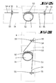
- Fig. 6
- die Seitenansicht gegen die Düse, eine Abhebestellung des Anschlussstutzens der Düse darstellend, bei strichpunktiert dargestellter abgehobener Stellung;
- Fig. 7
- die Seitenansicht gegen die Düse bei flachgelegter Stellung des Anschlussstutzens;
- Fig. 8
- eine der Fig. 6 oder 7 entsprechende Darstellung, jedoch die aufgeschwenkte Parkstellung des Anschlussstutzens betreffend;
- Fig. 9
- eine der Fig. 4 entsprechende Unteransicht der Düse, eine zweite Ausführungsform betreffend;
- Fig. 10
- eine weitere Unteransicht, eine dritte Ausführungsform betreffend;
- Fig. 11
- eine vierte Ausführungsform der Düse;
- Fig. 12
- die Unteransicht der Düse gemäß einer fünften Ausführungsform;
- Fig. 13
- eine schematische, partiell geschnittene Darstellung des Gelenkbereiches zwischen Düsenkörper und Düsenkopf, bei Ausrichtung des Düsenkopfes in normaler, der Flächenbearbeitung dienender Stellung;
- Fig. 14
- eine Unteransicht zu Fig. 13;
- Fig. 15
- eine der Fig. 14 entsprechende Darstellung, jedoch bei um 90° verschwenkter Position des Düsenkopfes;
- Fig. 16
- eine der Fig. 15 entsprechende Darstellung, jedoch eine alternative Ausgestaltung betreffend;
- Fig. 17
- eine der Fig. 14 entsprechende Darstellung, ein weiteres Ausführungsbeispiel betreffend;
- Fig. 18
- eine der Fig. 17 entsprechende Darstellung., jedoch bei um 90° verschwenkter Position des Düsenkopfes;
- Fig. 19
- eine schematische Schnittdarstellung durch den Gelenkbereich zwischen Düsenkörper und Düsenkopf bei Ausrichten des Düsenkopfes in normaler Stellung, eine weitere Ausführungsform betreffend;
- Fig. 20
- den Schnitt gemäß der Linie XX-XX in Fig. 19;
- Fig. 21
- eine der Fig. 20 entsprechende Schnittdarstellung mit einem Düsenkopf in Verschwenkstellung;
- Fig. 22
- eine schematische, partiell geschnittene Darstellung des Gelenkbereiches zwischen Düsenkörper und Düsenkopf, bei Ausrichtung des Düsenkopfes in normaler, der Flächenbearbeitung dienender Stellung, eine weitere Ausführungsform betreffend;
- Fig. 23
- den vergrößerten Schnitt gemäß der Linie XXIII-XXIII in Fig. 22;
- Fig. 24
- eine der Fig. 22 entsprechende Darstellung, jedoch bei um 90° verschwenkter Position des Düsenkopfes;
- Fig. 25
- eine der Fig. 22 entsprechende Darstellung, jedoch eine weitere Ausführungsform betreffend;
- Fig. 26
- die um 90° verschwenkte Position des Düsenkopfes gemäß der Ausführungsform in Fig. 25;
- Fig. 27
- eine weitere der Fig. 22 entsprechende Darstellung in einer weiteren Ausführungsform;
- Fig. 28
- die Darstellung des Düsenkopfes gemäß Fig. 27 in verschwenkter Position;
- Fig. 29
- eine weitere Ausführungsform des Düsenkopfes in einer Darstellung gemäß der Fig. 22;
- Fig. 30
- die verschwenkte Position des Düsenkopfes gemäß Fig. 29;
- Fig. 31 - Fig. 36
- weitere, der Darstellung in Fig. 22 entsprechende Darstellungen, weitere Ausführungsformen betreffend;
- Fig. 37
- die verschwenkte Position des Düsenkopfes in einer weiteren Ausführungsform gemäß Fig. 36;
- Fig. 38
- eine der Fig. 12 entsprechende Darstellung, eine weitere Ausführungsform betreffend.
Claims (9)
- Düse (2) für einen Staubsauger (1), insbesondere Hartbodendüse, mit einem auf dem Boden (3) aufsitzenden Düsenkopf (4) und einem den Düsenkopf (4) mit einem Staubsauger (1) verbindenden Düsenkörper (5), wobei an dem Düsenkörper (5) ein Anschlussstutzen (6) ausgebildet ist und die Düse (2) insgesamt mit Laufrollen (10) oder über Gleitflächen verfahrbar ist und wobei ein Saugkanal (7) vorgesehen ist, der, sich von dem Anschlussstutzen (6) durch den Düsenkörper (5) erstreckend, in dem Düsenkopf (4) mündet, dadurch gekennzeichnet, dass der Düsenkopf (4) relativ zu dem Düsenkörper (5) verschwenkbar ist.
- Düse nach Anspruch 1 oder insbesondere danach, dadurch gekennzeichnet, dass die Verschwenkbarkeit über ein Gelenk (12) mit einer vertikalen Gelenkachse (z) gebildet ist.
- Düse nach einem oder mehreren der vorhergehenden Ansprüche oder insbesondere danach, dadurch gekennzeichnet, dass der Düsenkopf (4) in Normalstellung eine größere Breite (b1) als Tiefe (t) aufweist.
- Düse nach einem oder mehreren der vorhergehenden Ansprüche oder insbesondere danach, dadurch gekennzeichnet, dass der Düsenkopf (4) einen kreissegmentartigen Grundriss aufweist.
- Düse nach einem oder mehreren der vorhergehenden Ansprüche oder insbesondere danach, dadurch gekennzeichnet, dass das Gelenk (12) im Bereich der größten Tiefe (t) des Düsenkopfes (4) ausgebildet ist.
- Düse nach einem oder mehreren der vorhergehenden Ansprüche oder insbesondere danach, dadurch gekennzeichnet, dass eine oder mehrere Vorzugs-Verschwenkstellungen des Düsenkopfes (4) gerastet sind.
- Düse nach einem oder mehreren der vorhergehenden Ansprüche oder insbesondere danach, dadurch gekennzeichnet, dass der Düsenkopf (4) nach einem Ausschwenken in eine Zwischenstellung federunterstützt in eine Grundoder Raststellung zurückschwenkt.
- Düse nach einem oder mehreren der vorhergehenden Ansprüche oder insbesondere danach, dadurch gekennzeichnet, dass eine Höhe (h2) des Düsenkopfes (4), bezogen auf die freie Vertikalerstreckung (h1) einer Borste eines Borstenabschnittes (16), einschließlich der Borsten dem Zwei- bis Fünffachen der freien vertikalen Länge (h1) der Borste entspricht.
- Düse nach einem oder mehreren der vorhergehenden Ansprüche oder insbesondere danach, dadurch gekennzeichnet, dass Mittel vorgesehen sind zur Beeinflussung eines Saugluftstromes (1) in Abhängigkeit von einer Verschwenkstellung des Düsenkopfes (4).
Applications Claiming Priority (8)
| Application Number | Priority Date | Filing Date | Title |
|---|---|---|---|
| DE10062058 | 2000-12-13 | ||
| DE10062058 | 2000-12-13 | ||
| DE10103849 | 2001-01-30 | ||
| DE10103849 | 2001-01-30 | ||
| DE10127174 | 2001-05-28 | ||
| DE10127174 | 2001-05-28 | ||
| DE10144129 | 2001-09-08 | ||
| DE10144129A DE10144129A1 (de) | 2000-12-13 | 2001-09-08 | Düse für einen Staubsauger |
Publications (3)
| Publication Number | Publication Date |
|---|---|
| EP1214902A2 true EP1214902A2 (de) | 2002-06-19 |
| EP1214902A3 EP1214902A3 (de) | 2004-12-29 |
| EP1214902B1 EP1214902B1 (de) | 2006-06-07 |
Family
ID=27437909
Family Applications (1)
| Application Number | Title | Priority Date | Filing Date |
|---|---|---|---|
| EP01129197A Expired - Lifetime EP1214902B1 (de) | 2000-12-13 | 2001-12-10 | Düse für einen Staubsauger |
Country Status (8)
| Country | Link |
|---|---|
| EP (1) | EP1214902B1 (de) |
| JP (1) | JP4159283B2 (de) |
| KR (1) | KR20020048866A (de) |
| CN (1) | CN1284498C (de) |
| AT (1) | ATE328523T1 (de) |
| DE (1) | DE50110028D1 (de) |
| ES (1) | ES2260147T3 (de) |
| HK (1) | HK1047026B (de) |
Cited By (7)
| Publication number | Priority date | Publication date | Assignee | Title |
|---|---|---|---|---|
| FR2847792A1 (fr) * | 2002-12-03 | 2004-06-04 | Millet Marius | Dispositif de succion pour aspirateur |
| RU2256393C2 (ru) * | 2003-09-12 | 2005-07-20 | Ульяновский государственный технический университет | Всасывающий насадок |
| US8752241B2 (en) | 2010-10-06 | 2014-06-17 | Duepro Ag | Vacuum cleaner nozzle with magnetic lock |
| DE102014107812A1 (de) | 2014-06-03 | 2015-12-03 | Vorwerk & Co. Interholding Gmbh | Staubsaugerdüse für einen Staubsauger |
| WO2016029968A1 (de) * | 2014-08-29 | 2016-03-03 | Alfred Kärcher Gmbh & Co. Kg | Saugdüse und hartflächenabsauggerät |
| DE202018104886U1 (de) | 2018-08-24 | 2019-11-26 | Vorwerk & Co. Interholding Gmbh | Saugdüse für einen Staubsauger |
| US12256884B2 (en) | 2018-08-08 | 2025-03-25 | Koninklijke Philips N.V. | Vacuum cleaner nozzle |
Families Citing this family (15)
| Publication number | Priority date | Publication date | Assignee | Title |
|---|---|---|---|---|
| JP4514652B2 (ja) * | 2005-05-26 | 2010-07-28 | 三洋電機株式会社 | 電気掃除機用吸込具 |
| JP4530940B2 (ja) * | 2005-08-10 | 2010-08-25 | 三洋電機株式会社 | 掃除機用アタッチメント |
| DE102008064211A1 (de) | 2008-12-08 | 2010-06-10 | Vorwerk & Co. Interholding Gmbh | Elektromotorisch betriebenes Flächenbearbeitungsgerät |
| KR101695281B1 (ko) * | 2010-05-14 | 2017-01-12 | 주식회사 탑 엔지니어링 | 전자부품 이송장치 |
| DE102012100457B4 (de) | 2012-01-20 | 2023-04-20 | Vorwerk & Co. Interholding Gmbh | Düse für einen Staubsauger |
| DE102013102266A1 (de) | 2013-03-07 | 2014-09-11 | Vorwerk & Co. Interholding Gmbh | Düse für einen Staubsauger |
| CN105491929B (zh) * | 2013-09-30 | 2017-09-22 | 皇家飞利浦有限公司 | 用于真空吸尘器的管嘴 |
| KR101637684B1 (ko) | 2014-09-26 | 2016-07-07 | 엘지전자 주식회사 | 진공 청소기 |
| DE102015109838A1 (de) * | 2015-06-19 | 2016-12-22 | Vorwerk & Co. Interholding Gmbh | Saugdüse für einen Staubsauger |
| WO2017041837A1 (de) * | 2015-09-09 | 2017-03-16 | Alfred Kärcher Gmbh & Co. Kg | Bodendüse |
| DE102016115576A1 (de) | 2016-08-23 | 2018-03-01 | Vorwerk & Co. Interholding Gmbh | Saugdüse für einen Staubsauger |
| DE102017107345A1 (de) * | 2017-04-05 | 2018-10-11 | Alfred Kärcher SE & Co. KG | Bodendüse für einen Dampfreiniger und Dampfreiniger |
| CN109497883B (zh) * | 2018-11-21 | 2020-08-04 | 河北工业大学 | 一种对带边框玻璃进行无盲区清洁的擦窗机器人 |
| DE202019100630U1 (de) | 2019-02-04 | 2020-05-05 | Vorwerk & Co. Interholding Gmbh | Bodendüse zur Verbindung mit einem Staubsauger |
| JP7353087B2 (ja) * | 2019-07-12 | 2023-09-29 | シャープ株式会社 | 電気掃除機の吸込口体およびそれを備えた電気掃除機 |
Family Cites Families (5)
| Publication number | Priority date | Publication date | Assignee | Title |
|---|---|---|---|---|
| JPH0284919A (ja) * | 1988-09-21 | 1990-03-26 | Orient Esuteeto:Kk | 電気掃除機用吸引ノズル |
| AU710797B2 (en) * | 1995-10-12 | 1999-09-30 | Nilfisk A/S | A connection element for a mouth piece |
| DE19962942C2 (de) * | 1999-12-24 | 2002-10-17 | Wessel Werk Gmbh | Bodendüse für Staubsauger |
| WO2001089356A1 (en) * | 2000-05-11 | 2001-11-29 | Koninklijke Philips Electronics N.V. | Suction attachment comprising a rotatable foot and a displaceable brush |
| US6532622B2 (en) * | 2000-05-17 | 2003-03-18 | Daewoo Electronics Co., Ltd. | Brush head of vacuum cleaner |
-
2001
- 2001-12-10 ES ES01129197T patent/ES2260147T3/es not_active Expired - Lifetime
- 2001-12-10 AT AT01129197T patent/ATE328523T1/de active
- 2001-12-10 DE DE50110028T patent/DE50110028D1/de not_active Expired - Lifetime
- 2001-12-10 EP EP01129197A patent/EP1214902B1/de not_active Expired - Lifetime
- 2001-12-11 JP JP2001376708A patent/JP4159283B2/ja not_active Expired - Fee Related
- 2001-12-13 KR KR1020010078847A patent/KR20020048866A/ko not_active Abandoned
- 2001-12-13 CN CNB011457406A patent/CN1284498C/zh not_active Expired - Lifetime
-
2002
- 2002-12-04 HK HK02108817.2A patent/HK1047026B/zh not_active IP Right Cessation
Cited By (9)
| Publication number | Priority date | Publication date | Assignee | Title |
|---|---|---|---|---|
| FR2847792A1 (fr) * | 2002-12-03 | 2004-06-04 | Millet Marius | Dispositif de succion pour aspirateur |
| RU2256393C2 (ru) * | 2003-09-12 | 2005-07-20 | Ульяновский государственный технический университет | Всасывающий насадок |
| US8752241B2 (en) | 2010-10-06 | 2014-06-17 | Duepro Ag | Vacuum cleaner nozzle with magnetic lock |
| DE102014107812A1 (de) | 2014-06-03 | 2015-12-03 | Vorwerk & Co. Interholding Gmbh | Staubsaugerdüse für einen Staubsauger |
| CN105266711A (zh) * | 2014-06-03 | 2016-01-27 | 德国福维克控股公司 | 用于吸尘器的吸尘器嘴 |
| CN105266711B (zh) * | 2014-06-03 | 2019-04-23 | 德国福维克控股公司 | 用于吸尘器的吸尘器嘴 |
| WO2016029968A1 (de) * | 2014-08-29 | 2016-03-03 | Alfred Kärcher Gmbh & Co. Kg | Saugdüse und hartflächenabsauggerät |
| US12256884B2 (en) | 2018-08-08 | 2025-03-25 | Koninklijke Philips N.V. | Vacuum cleaner nozzle |
| DE202018104886U1 (de) | 2018-08-24 | 2019-11-26 | Vorwerk & Co. Interholding Gmbh | Saugdüse für einen Staubsauger |
Also Published As
| Publication number | Publication date |
|---|---|
| KR20020048866A (ko) | 2002-06-24 |
| EP1214902A3 (de) | 2004-12-29 |
| DE50110028D1 (de) | 2006-07-20 |
| JP4159283B2 (ja) | 2008-10-01 |
| ATE328523T1 (de) | 2006-06-15 |
| JP2002177173A (ja) | 2002-06-25 |
| HK1047026A1 (en) | 2003-02-07 |
| CN1364439A (zh) | 2002-08-21 |
| ES2260147T3 (es) | 2006-11-01 |
| CN1284498C (zh) | 2006-11-15 |
| HK1047026B (zh) | 2006-10-27 |
| EP1214902B1 (de) | 2006-06-07 |
Similar Documents
| Publication | Publication Date | Title |
|---|---|---|
| EP1214902A2 (de) | Düse für einen Staubsauger | |
| DE4304681C2 (de) | Einteilige Staubsaugerdüse | |
| EP2449934B1 (de) | Saugdüsenanordnung für einen Bodenstaubsauger | |
| DE202006006065U1 (de) | Unterflur-Führungsanordnung für Möbelteile, insbesondere im Korpus von Möbelstücken | |
| DE102012108285A1 (de) | Bodenwischgerät sowie relativ zu einem Festteil schwingend angetriebener Körper | |
| DE202011000624U1 (de) | Werkzeugadapter | |
| EP1449477A2 (de) | Staubsaugerdüse für Glattböden und textile Bodenbeläge | |
| DE60124266T2 (de) | Staubsaugermundstück | |
| EP2640248B1 (de) | Bodenreinigungsgerät mit schwenkbarer schmutzaufnahme | |
| DE102009029806B4 (de) | Bodendüse für Staubsauger | |
| EP4260756A1 (de) | Reinigungsgerät, kehrbürste für ein reinigungsgerät und verfahren zum betreiben eines reinigungsgeräts | |
| EP1367931B1 (de) | Kippgelenkausbildung eines staubsauger-saugkanals | |
| DE102004061971B4 (de) | Bodendüse für Staubsauger | |
| DE3414862C2 (de) | ||
| EP4260782A1 (de) | Reinigungsgerät und kehrbürste für ein reinigungsgerät | |
| DE10144129A1 (de) | Düse für einen Staubsauger | |
| DE4429212C1 (de) | Flachwischgerät mit teilweise blockierbarem Kardangelenk | |
| EP4209644B1 (de) | Werkzeug zum nachbearbeiten von mit einer fugenmasse gefüllten fugen | |
| DE69408026T2 (de) | Staubsaugerdüse | |
| DE202004003944U1 (de) | Fußbodenleiste | |
| DE102007057349B4 (de) | Bodendüse für Staubsauger | |
| DE102007036524A1 (de) | Vorsatzdüse für einen Staubsauger | |
| EP4260758A1 (de) | Reinigungsgerät und kehrbürste für ein reinigungsgerät | |
| EP4260757A1 (de) | Reinigungsgerät, kehrbürste für ein reinigungsgerät und verfahren zum betreiben eines reinigungsgeräts | |
| DE102018003607B3 (de) | Scharnier-Vorrichtung |
Legal Events
| Date | Code | Title | Description |
|---|---|---|---|
| PUAI | Public reference made under article 153(3) epc to a published international application that has entered the european phase |
Free format text: ORIGINAL CODE: 0009012 |
|
| AK | Designated contracting states |
Kind code of ref document: A2 Designated state(s): AT BE CH CY DE DK ES FI FR GB GR IE IT LI LU MC NL PT SE TR |
|
| AX | Request for extension of the european patent |
Free format text: AL;LT;LV;MK;RO;SI |
|
| PUAL | Search report despatched |
Free format text: ORIGINAL CODE: 0009013 |
|
| AK | Designated contracting states |
Kind code of ref document: A3 Designated state(s): AT BE CH CY DE DK ES FI FR GB GR IE IT LI LU MC NL PT SE TR |
|
| AX | Request for extension of the european patent |
Extension state: AL LT LV MK RO SI |
|
| 17P | Request for examination filed |
Effective date: 20050314 |
|
| 17Q | First examination report despatched |
Effective date: 20050518 |
|
| AKX | Designation fees paid |
Designated state(s): AT BE CH CY DE DK ES FI FR GB GR IE IT LI LU MC NL PT SE TR |
|
| GRAP | Despatch of communication of intention to grant a patent |
Free format text: ORIGINAL CODE: EPIDOSNIGR1 |
|
| RIN1 | Information on inventor provided before grant (corrected) |
Inventor name: CORNELISSEN, MARKUS Inventor name: STROHMEYER, ROLF Inventor name: KECK, ULRICH Inventor name: SAND, THOMAS Inventor name: MARAFANTE, GENTILE Inventor name: SCHEUREN, BERNHARD Inventor name: LEHMANN, PETRA Inventor name: JACOBS, CARSTEN, DR. |
|
| GRAS | Grant fee paid |
Free format text: ORIGINAL CODE: EPIDOSNIGR3 |
|
| GRAA | (expected) grant |
Free format text: ORIGINAL CODE: 0009210 |
|
| AK | Designated contracting states |
Kind code of ref document: B1 Designated state(s): AT BE CH CY DE DK ES FI FR GB GR IE IT LI LU MC NL PT SE TR |
|
| PG25 | Lapsed in a contracting state [announced via postgrant information from national office to epo] |
Ref country code: IE Free format text: LAPSE BECAUSE OF FAILURE TO SUBMIT A TRANSLATION OF THE DESCRIPTION OR TO PAY THE FEE WITHIN THE PRESCRIBED TIME-LIMIT Effective date: 20060607 |
|
| REG | Reference to a national code |
Ref country code: GB Ref legal event code: FG4D Free format text: NOT ENGLISH |
|
| REG | Reference to a national code |
Ref country code: CH Ref legal event code: EP |
|
| GBT | Gb: translation of ep patent filed (gb section 77(6)(a)/1977) |
Effective date: 20060607 |
|
| REG | Reference to a national code |
Ref country code: IE Ref legal event code: FG4D Free format text: LANGUAGE OF EP DOCUMENT: GERMAN |
|
| REG | Reference to a national code |
Ref country code: SE Ref legal event code: TRGR |
|
| REF | Corresponds to: |
Ref document number: 50110028 Country of ref document: DE Date of ref document: 20060720 Kind code of ref document: P |
|
| PG25 | Lapsed in a contracting state [announced via postgrant information from national office to epo] |
Ref country code: DK Free format text: LAPSE BECAUSE OF FAILURE TO SUBMIT A TRANSLATION OF THE DESCRIPTION OR TO PAY THE FEE WITHIN THE PRESCRIBED TIME-LIMIT Effective date: 20060907 |
|
| REG | Reference to a national code |
Ref country code: HK Ref legal event code: GR Ref document number: 1047026 Country of ref document: HK |
|
| REG | Reference to a national code |
Ref country code: ES Ref legal event code: FG2A Ref document number: 2260147 Country of ref document: ES Kind code of ref document: T3 |
|
| PG25 | Lapsed in a contracting state [announced via postgrant information from national office to epo] |
Ref country code: PT Free format text: LAPSE BECAUSE OF FAILURE TO SUBMIT A TRANSLATION OF THE DESCRIPTION OR TO PAY THE FEE WITHIN THE PRESCRIBED TIME-LIMIT Effective date: 20061107 |
|
| ET | Fr: translation filed | ||
| PGFP | Annual fee paid to national office [announced via postgrant information from national office to epo] |
Ref country code: TR Payment date: 20061130 Year of fee payment: 6 |
|
| PGFP | Annual fee paid to national office [announced via postgrant information from national office to epo] |
Ref country code: GB Payment date: 20061211 Year of fee payment: 6 Ref country code: NL Payment date: 20061211 Year of fee payment: 6 |
|
| PGFP | Annual fee paid to national office [announced via postgrant information from national office to epo] |
Ref country code: FI Payment date: 20061212 Year of fee payment: 6 |
|
| PGFP | Annual fee paid to national office [announced via postgrant information from national office to epo] |
Ref country code: SE Payment date: 20061213 Year of fee payment: 6 |
|
| PG25 | Lapsed in a contracting state [announced via postgrant information from national office to epo] |
Ref country code: LI Free format text: LAPSE BECAUSE OF NON-PAYMENT OF DUE FEES Effective date: 20061231 Ref country code: BE Free format text: LAPSE BECAUSE OF NON-PAYMENT OF DUE FEES Effective date: 20061231 Ref country code: CH Free format text: LAPSE BECAUSE OF NON-PAYMENT OF DUE FEES Effective date: 20061231 Ref country code: MC Free format text: LAPSE BECAUSE OF NON-PAYMENT OF DUE FEES Effective date: 20061231 |
|
| REG | Reference to a national code |
Ref country code: IE Ref legal event code: FD4D |
|
| PLBE | No opposition filed within time limit |
Free format text: ORIGINAL CODE: 0009261 |
|
| STAA | Information on the status of an ep patent application or granted ep patent |
Free format text: STATUS: NO OPPOSITION FILED WITHIN TIME LIMIT |
|
| 26N | No opposition filed |
Effective date: 20070308 |
|
| REG | Reference to a national code |
Ref country code: CH Ref legal event code: PL |
|
| BERE | Be: lapsed |
Owner name: VORWERK & CO. INTERHOLDING G.M.B.H. Effective date: 20061231 |
|
| PG25 | Lapsed in a contracting state [announced via postgrant information from national office to epo] |
Ref country code: GR Free format text: LAPSE BECAUSE OF FAILURE TO SUBMIT A TRANSLATION OF THE DESCRIPTION OR TO PAY THE FEE WITHIN THE PRESCRIBED TIME-LIMIT Effective date: 20060908 |
|
| PG25 | Lapsed in a contracting state [announced via postgrant information from national office to epo] |
Ref country code: LU Free format text: LAPSE BECAUSE OF NON-PAYMENT OF DUE FEES Effective date: 20061210 Ref country code: FI Free format text: LAPSE BECAUSE OF NON-PAYMENT OF DUE FEES Effective date: 20071210 |
|
| EUG | Se: european patent has lapsed | ||
| GBPC | Gb: european patent ceased through non-payment of renewal fee |
Effective date: 20071210 |
|
| NLV4 | Nl: lapsed or anulled due to non-payment of the annual fee |
Effective date: 20080701 |
|
| PG25 | Lapsed in a contracting state [announced via postgrant information from national office to epo] |
Ref country code: SE Free format text: LAPSE BECAUSE OF NON-PAYMENT OF DUE FEES Effective date: 20071211 |
|
| PG25 | Lapsed in a contracting state [announced via postgrant information from national office to epo] |
Ref country code: NL Free format text: LAPSE BECAUSE OF NON-PAYMENT OF DUE FEES Effective date: 20080701 Ref country code: CY Free format text: LAPSE BECAUSE OF FAILURE TO SUBMIT A TRANSLATION OF THE DESCRIPTION OR TO PAY THE FEE WITHIN THE PRESCRIBED TIME-LIMIT Effective date: 20060607 |
|
| PG25 | Lapsed in a contracting state [announced via postgrant information from national office to epo] |
Ref country code: GB Free format text: LAPSE BECAUSE OF NON-PAYMENT OF DUE FEES Effective date: 20071210 |
|
| PG25 | Lapsed in a contracting state [announced via postgrant information from national office to epo] |
Ref country code: TR Free format text: LAPSE BECAUSE OF FAILURE TO SUBMIT A TRANSLATION OF THE DESCRIPTION OR TO PAY THE FEE WITHIN THE PRESCRIBED TIME-LIMIT Effective date: 20060607 |
|
| REG | Reference to a national code |
Ref country code: FR Ref legal event code: PLFP Year of fee payment: 15 |
|
| REG | Reference to a national code |
Ref country code: FR Ref legal event code: PLFP Year of fee payment: 16 |
|
| REG | Reference to a national code |
Ref country code: FR Ref legal event code: PLFP Year of fee payment: 17 |
|
| PGFP | Annual fee paid to national office [announced via postgrant information from national office to epo] |
Ref country code: AT Payment date: 20191213 Year of fee payment: 19 |
|
| PGFP | Annual fee paid to national office [announced via postgrant information from national office to epo] |
Ref country code: DE Payment date: 20201216 Year of fee payment: 20 Ref country code: FR Payment date: 20201217 Year of fee payment: 20 |
|
| PGFP | Annual fee paid to national office [announced via postgrant information from national office to epo] |
Ref country code: ES Payment date: 20210122 Year of fee payment: 20 |
|
| REG | Reference to a national code |
Ref country code: AT Ref legal event code: MM01 Ref document number: 328523 Country of ref document: AT Kind code of ref document: T Effective date: 20201210 |
|
| PG25 | Lapsed in a contracting state [announced via postgrant information from national office to epo] |
Ref country code: AT Free format text: LAPSE BECAUSE OF NON-PAYMENT OF DUE FEES Effective date: 20201210 |
|
| PGFP | Annual fee paid to national office [announced via postgrant information from national office to epo] |
Ref country code: IT Payment date: 20201230 Year of fee payment: 20 |
|
| REG | Reference to a national code |
Ref country code: DE Ref legal event code: R071 Ref document number: 50110028 Country of ref document: DE |
|
| REG | Reference to a national code |
Ref country code: ES Ref legal event code: FD2A Effective date: 20220405 |
|
| PG25 | Lapsed in a contracting state [announced via postgrant information from national office to epo] |
Ref country code: ES Free format text: LAPSE BECAUSE OF EXPIRATION OF PROTECTION Effective date: 20211211 |