EP1214473B1 - Gleisweiche - Google Patents
Gleisweiche Download PDFInfo
- Publication number
- EP1214473B1 EP1214473B1 EP00958083A EP00958083A EP1214473B1 EP 1214473 B1 EP1214473 B1 EP 1214473B1 EP 00958083 A EP00958083 A EP 00958083A EP 00958083 A EP00958083 A EP 00958083A EP 1214473 B1 EP1214473 B1 EP 1214473B1
- Authority
- EP
- European Patent Office
- Prior art keywords
- rails
- track
- switch point
- distancing means
- rail section
- Prior art date
- Legal status (The legal status is an assumption and is not a legal conclusion. Google has not performed a legal analysis and makes no representation as to the accuracy of the status listed.)
- Expired - Lifetime
Links
- 230000008859 change Effects 0.000 claims description 9
- 241001669679 Eleotris Species 0.000 claims description 3
- 238000006073 displacement reaction Methods 0.000 abstract description 3
- 125000006850 spacer group Chemical group 0.000 description 11
- 238000005452 bending Methods 0.000 description 5
- 230000015572 biosynthetic process Effects 0.000 description 4
- 230000000295 complement effect Effects 0.000 description 3
- 238000010276 construction Methods 0.000 description 3
- 230000007704 transition Effects 0.000 description 3
- 150000001875 compounds Chemical class 0.000 description 2
- 230000001419 dependent effect Effects 0.000 description 2
- 230000000694 effects Effects 0.000 description 2
- 238000005339 levitation Methods 0.000 description 2
- 238000004519 manufacturing process Methods 0.000 description 2
- 230000007246 mechanism Effects 0.000 description 2
- 230000009471 action Effects 0.000 description 1
- 238000011109 contamination Methods 0.000 description 1
- 230000008878 coupling Effects 0.000 description 1
- 238000010168 coupling process Methods 0.000 description 1
- 238000005859 coupling reaction Methods 0.000 description 1
- 239000013013 elastic material Substances 0.000 description 1
- 238000004091 panning Methods 0.000 description 1
Images


Classifications
-
- E—FIXED CONSTRUCTIONS
- E01—CONSTRUCTION OF ROADS, RAILWAYS, OR BRIDGES
- E01B—PERMANENT WAY; PERMANENT-WAY TOOLS; MACHINES FOR MAKING RAILWAYS OF ALL KINDS
- E01B25/00—Tracks for special kinds of railways
- E01B25/22—Tracks for railways with the vehicle suspended from rigid supporting rails
- E01B25/26—Switches; Crossings
-
- E—FIXED CONSTRUCTIONS
- E01—CONSTRUCTION OF ROADS, RAILWAYS, OR BRIDGES
- E01B—PERMANENT WAY; PERMANENT-WAY TOOLS; MACHINES FOR MAKING RAILWAYS OF ALL KINDS
- E01B25/00—Tracks for special kinds of railways
- E01B25/02—Tracks for rack railways
- E01B25/06—Switches; Frogs; Crossings
-
- E—FIXED CONSTRUCTIONS
- E01—CONSTRUCTION OF ROADS, RAILWAYS, OR BRIDGES
- E01B—PERMANENT WAY; PERMANENT-WAY TOOLS; MACHINES FOR MAKING RAILWAYS OF ALL KINDS
- E01B7/00—Switches; Crossings
- E01B7/02—Tongues; Associated constructions
- E01B7/06—Constructions with flexible tongues or flexible fishplates
Definitions
- the present invention relates to a track switch according to the preamble of Patent claim 1.
- WO98 / 05820 shows a crossover connection for lane guideways Vehicles (maglev trains and the like). This transfer connection is used to change the lane and is therefore no switch for conventional railways is suitable. The routes are in this construction of a vehicle only each covers and therefore therefore in comparison to conventional railways no requirements regarding the parallelism of several Track stretches meet.
- the invention disclosed herein relates to a switch for railroads and others Rail-bound transport and conveying means, two or more per lane more track strands, tracks, racks and similar, parallel elements, be moved at the same distance by the same distance, so that they are in their endsteltitch over their entire length take a given distance to each other and correspond with subsequent track sections.
- the invention is suitable For example, for track switches of gear and cable cars where between the two tracks another element, e.g. a rack, parallel to the tracks (Track strands) is arranged.
- the invention is only insignificant on the free bending length of the track sections to be moved and also guarantees that the track strands have a continuous, predetermined curvature can.
- the switch disclosed here for railways and other rail-bound transport and conveying means comprises a first track section, alternatively with at least two further track sections over one by elastic material deformation pivotable track section is connected.
- the swiveling track section consists of several, parallel elastically bendable Elements, such as rails and racks, which by means of distance-related means distributed over their length, are preferably interconnected at discrete locations.
- the several elastic bendable elements correspond in the end positions with the track sections and point to each other at the required locations or sections a defined distance. Discrepancies are avoided as far as possible.
- the distance between the moving track sections by regularly or irregularly arranged and with the tracks Actively connected spacer means guaranteed.
- the distance means are so with the Track sections that they are not locally relevant, disadvantageous partial stiffening of a track section lead. This ensures that optimal requirements for continuous curvature and a constant Distance to be guaranteed.
- the operatively connected spacers are advantageously arranged below or between the track strands. In a positioning below the track strands they can be integrated into sleepers.
- the spacer means are operatively connected to the track strands so that the required Distance between the track strands always or only in the end positions is complied with.
- the threshold bodies can be arranged so that at Loading the switch a self-locking occurs, causing an unintentional shifting is deliberately avoided.
- An embodiment in which the distance between the tracks is always respected remains, based on sill-like spacers that are designed so that their extent determining the spatial distance between the tracks in each position of the pivoting movement of the tracks not changed.
- This will be for example by spacer means arranged at right angles to the track strands reached, who are so connected with the track strands that they are theirs relative position, especially the angles, do not change.
- a corresponding active compound between a rail track and the distance means can e.g. thereby be achieved that certain spacers have grooves at certain points, which are arranged substantially parallel to the track strands. In these Grooves engage tenons which in turn are connected to the track.
- the distance means and the operative connection between these and the Track strands are in particular designed so that they are not disadvantageous Partial stiffening of the track section to be pivoted, the free Bend length not significantly influence and not to a polygon formation to lead. A coordination of the movements between the distance center and the Tracks are guaranteed by appropriate means.
- a further advantageous embodiment consists in spacer means in the form of Swell bodies via hinged joints with the track sections hinged to connect.
- the distance between the track strands and the other parallel elements during pivoting specifically changed.
- the inventive arrangement of the threshold body is achieved, however, that at least in two end positions of the distance between the track strands and the other parallel elements is exactly maintained.
- a corresponding arrangement guarantees that, due to complementary angles, the distance between the track strands and the other parallel Elements in the final positions meets the required specifications.
- the articulated Compounds are highly resilient, inexpensive to manufacture and have low friction on. They are particularly easy to maintain and reliable. In addition, stands thereby, if necessary, the entire bending length of the pivotable track section Available. This will, unlike other orders, not be supplemented by additional limited the free bending length obstructing elements. The danger of a Polygon formation due to varying stiffness of the cross sections is deliberately avoided which is particularly advantageous for fast-moving transport systems.
- the Advantageously, threshold bodies are supported on the substructure of the switch or other limiting elements that frictional or positive locking the Track strands and the other parallel elements at high loads secured against lateral displacement.
- the support provides in particular that the switch in the unloaded state switched without much effort can be, but in the (eg by a subsidy) loaded state an unwanted Displacement prevented.
- Inventive switches are characterized by their insensitivity to weather influences. Through a coupling with In addition, it is achieved that the thermal expansion is equalized become. The inventive switches are particularly against pollution insensitive.
- the course of the curvature is in the straight and in the deflected position if necessary by mechanical Guarantees attacks or similar elements of action. Basically it is so possible to realize any curves. If necessary, secure additional Elements (locking mechanisms) the track strands in the end positions.
- the fixed points of the switch are chosen so that a thermal elongation the transitions between the fixed and the moving track sections not influenced or compensated. By a corresponding structure of Weichenunterbaus is achieved that thermal changes are especially at Gear or cable cars do not care about the operational safety and the pitch of the racks impact.
- the transitions between the individual track sections will be designed so that no unwanted contact during pivoting arises.
- Servo systems for example in the form of mechanical, electrical, hydraulic servomotors and lever systems, etc. used. These are about Lever systems operatively connected to the tracks.
- FIG 1 shows schematically a preferred embodiment of a switch 1 for a rack railway in a perspective view.
- the switch 1 includes a first track section 2 which is connectable to two further track sections 3 and 4 via a laterally deflectable, movable track section 10.
- the movable track section 10 has two end positions. In the first end position illustrated here, the track section 10 connects the track sections 2 and 3. In the second end position (see Figure 3), the track section 10 connects the track sections 2 and 4.
- the track sections 2, 3, 4 and 10 each have two here parallel running tracks 30.1, 30.2, 35.1, 35.2, 40.1, 40.2, 45.1, 45.2 and each have a centrally extending rack 31, 36, 41, 46 on.
- the tracks 30.1, 30.2, 35.1, 35.2, 40.1, 40.2 and the rack 31, 36, 41 are rigidly connected to each other at the track sections 2, 3 and 4 via threshold body 13.
- a substructure 20 represents a firm connection between the track sections 2, 3 and 4.
- the movable track section 10 is mounted laterally pivotable on the substructure 20.
- the tracks 45.1 and 45.2, as well as the centrally extending rack 46 are operatively connected via joints 14 with threshold bodies 15 (see FIG.
- the threshold body 15 are here on the substructure 20 and are laterally displaceable in the unloaded state. When loading the switch, for example, by a railway car, the threshold body 15 are pressed against the base 20 here, whereby the track section 10 is stabilized.
- the tracks 45.1 and 45.2 and the rack 46 of the movable track section 10 are fixedly connected to the substructure 20 via a clamping point 16 (fixed point). Due to the articulated connection between the track strands 45.1 and 45.2, and the rack 46 and the threshold bodies 15 of the track section 10 laterally, parallel to the surface of the substructure 20 pivotally, so that it in a first end position the track section 2 with the track section 3 and in a second end position connects the track section 2 with the track section 4. These end positions are secured by stops 21 and 22 connected to the base 20. The positioning of the stops 20 and 21, the course of the tracks 45.1 and 45.2 and the rack 46 is defined. If necessary, additional elements are used to prevent unintentional lateral movement.
- the threshold bodies 15 coordinate and determine the parallel distance between the tracks 45.1 and 45.2 and the rack 46. They have a variable angle f (compare FIGS. 3 and 4) with respect to the tracks 45.1 and 45.2 and the rack 46. The arrangement is chosen so that this angle f is the same in the predetermined end positions (see FIG. 2). This guarantees that the distance between the tracks 45.1 and 45.2 and the rack 46 in the end positions corresponds to the specifications.
- Figure 2 shows a detailed view of Figure 1.
- the viewer looks in the direction of an arrow A.
- the axis of the joints 14 runs parallel to the z-axis here.
- the lateral end positions of the tracks 45.1, 45.2 and the rack 46 is ensured here by acting on a threshold body 15 end stops 21 and 22.
- the track strands (tracks 45.1 and 45.2, and rack 46) are connected via a clamping point 16 (fixed point) fixed to the base 20.
- the substructure and the track strands are designed so that thermally induced changes in length are compensated.
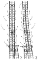
- FIG. 3 shows the switch 1 according to FIG. 1 in a plan view.
- the stationary track sections 2, 3 and 4 and the laterally pivotable track section 10. This is in a first end position, so that it connects the two track sections 2 and 4 in a straight line.
- the threshold body 15 are in this position with the stops 21 in abutment.
- each of the hingedly connected to the tracks 45.1 and 45.2 and the rack 46 threshold body 15 have a different angle f1 to f10 relative to the tracks 45.1 and 45.2 and the rack 46.
- the angles f1 to f10 are dependent on the course of the predetermined deflection of the pivotable track section 10. They are chosen so that the distance between the parallel tracks 45.1 and 45.2, and the rack 46 is accurately maintained in the end positions.
- angles f1 to f10 of the corresponding threshold body 15 in the first straight position shown here and the angles f1 'to f10' of the corresponding threshold body in the deflected second position are the same (complementary) ,
- Figure 4 shows the switch according to Figure 1 with deflected track section 10.
- the track section 10 connects in this position, the track sections 2 and 3.
- the course of the curved track section 10 is defined here by the stops 22, so that the predetermined course of the curvature is met. Due to the inventive arrangement of the sleeper body 15 and its articulated connection with the tracks 45.1 and 45.2, and the rack 46, a free bending length L of the tracks 45.1, 45.2 and the rack 46 is only affected in vain. As a result, the actuating forces P1, P2 acting here in two places are particularly low.
- the course and the radius of the curvature is defined here by a corresponding arrangement of the stops 22 constant or arbitrarily variable.
- the track strands 45.1, 45.2 and the rack 46 of the movable track section 10 are connected at a clamping point 16 fixed to the base 20 of the switch 1.
- the tracks 30.1, 30.2, 35.1, 35.2, 40.1, 40.2 and the racks 31, 36, 41st are at the clamping points 17, 18 and 19 also fixed to the base 20 of the Switch 1 connected.
- the substructure 20 is so on the movable track section 10 that thermal length changes of the track strands 45.1, 45.2, 46 equalized by a corresponding changes in length of the substructure 20 become. This means that an extension of the track strands 45.1 and 45.2 and the rack 46 compensated by a corresponding change in length of the substructure 20 (compensated) becomes. This will u.a.
- points for example a threshold body
- other points for example a threshold body, can also be used 15 are designed as a fixed point in one direction.
- a threshold body 15 By in Grooves guided rollers (not shown), which serve as guide elements for a or more threshold body 15 serve. Equivalent solutions are conceivable. Other Arrangements of the fixed points 16 to 19 and of compensation elements are of course possible.
- FIG. 5 schematically shows a further embodiment of a switch according to the invention.
- This embodiment has in the region of the movable track section 10 to the track strands 45.1, 45.2, 46 perpendicular frame-shaped spacer means 26 which are rigidly connected at several points to the tracks 45.1 and 45.2 and between the track strands 45.1, 45.2 and the rack 46 (on each page) are arranged.
- the spacer means 26 are arranged longitudinally displaceable in the direction of the rack 46, so that the mobility necessary for the pivoting results.
- the spacers are separated by columns 23.1, 23.2. These columns 23.1, 23.2 are closed or opened depending on the direction of the track section 10. In the situation shown here, in which the track section 10 is "straight", the columns 23.1 on one side of the rack 46 to stop (closed) and the columns 23.2 on the other side of the rack 46 are open.
- the track strands 45.1, 45.2, 46 remain approximately during the entire pivoting movement parallel.
- This embodiment is suitable for example with points a relatively small deflection and a switch heart.
- the bending line is over defines the gaps between the spacers, which depends on the Go to the end position to the stop. With larger deflections it may under certain circumstances come to a polygon formation.
- the adjusting forces for placing the switch will be introduced via a lever system 27.
- FIG. 6 shows the arrangement according to FIG. 5 in a second position, in which the track section 10 is "deflected". In this position, in contrast to the situation shown in Figure 5, the columns 23.2 to stop and the columns 23.1 "open".
Landscapes
- Engineering & Computer Science (AREA)
- Mechanical Engineering (AREA)
- Architecture (AREA)
- Civil Engineering (AREA)
- Structural Engineering (AREA)
- Magnetic Heads (AREA)
- Train Traffic Observation, Control, And Security (AREA)
- Railway Tracks (AREA)
- Adjustment Of The Magnetic Head Position Track Following On Tapes (AREA)
- Cold Cathode And The Manufacture (AREA)
- Inorganic Insulating Materials (AREA)
Description
- Fig. 1
- zeigt eine Ausführungsform einer Weiche in perspektivischer Ansicht,
- Fig.2
- zeigt eine Detaildarstellung aus Fig. 1,
- Fig. 3
- zeigt die Weiche gemäss Fig. 1 in einer ersten Stellung,
- Fig. 4
- zeigt eine Weiche gemäss Fig. 1 in einer zweiten Stellung,
- Fig. 5
- zeigt eine weitere Ausführungsform,
- Fig. 6
- zeigt die Ausführungsform von Figur 5 in einer weiteren Darstellung.
Claims (10)
- Weiche (1) für Eisenbahnen und andere schienengebundene Fördermittel mit einem ersten (2) und mindestens zwei zweiten Gleisabschnitten (3, 4), die über Fixpunkte (17, 18, 19) mit einem Unterbau (20) verbunden sind, und mit einem dritten Gleisabschnitt (10) der auf dem Unterbau (20) gelagert durch ein Stellmittel (27) seitlich verbiegbar angeordnet zum wahlweisen Verbinden des ersten (2) mit einem der zwei zweiten Gleisabschnitte (3, 4) in definierten Endpositionen dient, dadurch gekennzeichnet, dass der dritte Gleisabschnitt (10) mindestens zwei elastisch verbiegbare Gleisstränge (45.1, 45.2, 46) aufweist, die über einen Fixpunkt (16) mit dem Unterbau (20) verbunden sind und die über zugeordnete Distanzmittel (15, 26) gelenkig miteinander wirkverbunden sind, welche Distanzmittel (15, 26) über die Länge der verbiegbaren Gleisstränge verteilt derart angeordnet und ausgebildet sind, dass die mindestens zwei elastisch verbiegbaren Gleisstränge (45.1, 45.2, 46) zumindest in den zwei durch mechanische Anschläge (21, 22, 23.1, 23.2) definierten Endposition parallel zueinander angeordnet sind.
- Weiche (1) gemäss Patentanspruch 1, dadurch gekennzeichnet, dass die Distanzmittel (15) über Gelenke (14) drehbar mit den mindestens zwei elastisch verbiegbaren Gleissträngen (45.1, 45.2, 46) des dritten Gleisabschnittes (10) verbunden sind und dass die Distanzmittel (15) in einer ersten Endposition gegenüber den mindestens zwei elastisch verbiegbaren Gleissträngen (45.1, 45.2, 46) einen ersten Winkel (f1 bis f10) aufweisen und in einer zweiten Endposition einen zweiten Winkel (f1' bis f10') aufweisen, der zum ersten Winkel komplementär gleich ist.
- Weiche (1) gemäss Patentanspruch 2, dadurch gekennzeichnet, dass die Distanzmittel (15) in Schwellenkörpern (13) integriert sind.
- Weiche (1) gemäss einem der Patentansprüche 1 bis 3, dadurch gekennzeichnet, dass die mechanischen Anschläge (21, 22), welche die Endpositionen des beweglichen Gleisabschnitts (20) definierenden, mit dem Unterbau (20) verbunden sind.
- Weiche (1) gemäss einem der vorangehenden Patentansprüche, dadurch gekennzeichnet, dass der dritte Gleisabschnitt (10) zwei elastisch verbiegbare Gleisstränge (45.1, 45.2) und eine dazwischen angeordnete Zahnstange aufweist (46).
- Weiche (1) gemäss Patentanspruch 1, dadurch gekennzeichnet, die Distanzmittel (26) in einem rechten Winkel zu den Gleissträngen (45.1, 45.2, 46) angeordnet sind und derart mit diesen wirkverbunden sind, dass sie ihre relative Position, insbesondere den Winkel, gegenüber diesen nicht ändern.
- Weiche (1) gemäss Patentanspruch 6, dadurch gekennzeichnet, dass die Wirkverbindung zwischen den Distanzmitteln (26) und einem Gleisstrang (46) Zapfen aufweist, die in Nuten geführt sind, welche Nuten im wesentlichen parallel zum Gleisstrang (46) angeordnet sind, derart dass beim Auslenken der zu bewegenden Gleisabschnitte der relative Abstand zwischen den Gleisabschnitten beibehalten und ein Verschwenken dennoch nicht behindert wird.
- Weiche (1) gemäss einem der Patentansprüche 6 und 7, dadurch gekennzeichnet, dass rahmenförmige Distanzmittel (26) zwischen den äusseren Gleissträngen (45.1, 45.2) und einer zwischen den äusseren Gleissträngen (45.1, 45.2) verlaufenden Zahnstange (46) angeordnet sind, dass die Distanzmittel (26) an mehreren Stellen starr mit einer der äusseren Gleisstränge (45.1, 45.2) verbunden sind und dass die Distanzmittel (26) gegenüber der Zahnstange (46) in Richtung der Zahnstange (46) längs verschiebbar sind, derart dass die für ein seitliches Verschwenken des beweglichen Gleisabschnitts (10) notwendige Beweglichkeit resultiert.
- Weiche gemäss Patentanspruch 8, dadurch gekennzeichnet, dass die Distanzmittel (26) untereinander durch Spalten (23.1, 23.2) getrennt sind, welche Spalten (23.1, 23.2) derart angeordnet sind, dass sie abhängig von der Endposition des beweglichen Gleisabschnitts (10) geschlossen oder geöffnet sind und so als mechanischer Anschlag dienen.
- Weiche (1) gemäss einem der vorangehenden Patentansprüche, dadurch gekennzeichnet, dass die thermische Längenänderung des Unterbaus (20) so auf die thermische Längenänderung des beweglichen Gleisabschnitts (10) abgestimmt ist, dass eine thermische Längenänderungen der mindestens zwei elastischen Gleisstränge (45.1, 45.2, 46) durch eine entsprechende Längenänderung des Unterbaus (20) ausgeglichen wird.
Applications Claiming Priority (3)
| Application Number | Priority Date | Filing Date | Title |
|---|---|---|---|
| CH171599 | 1999-09-17 | ||
| CH171599 | 1999-09-17 | ||
| PCT/CH2000/000502 WO2001021894A1 (de) | 1999-09-17 | 2000-09-18 | Gleisweiche |
Publications (2)
| Publication Number | Publication Date |
|---|---|
| EP1214473A1 EP1214473A1 (de) | 2002-06-19 |
| EP1214473B1 true EP1214473B1 (de) | 2005-07-20 |
Family
ID=4216913
Family Applications (2)
| Application Number | Title | Priority Date | Filing Date |
|---|---|---|---|
| EP00958083A Expired - Lifetime EP1214473B1 (de) | 1999-09-17 | 2000-09-18 | Gleisweiche |
| EP00958084A Expired - Lifetime EP1214474B1 (de) | 1999-09-17 | 2000-09-18 | Gleisweiche |
Family Applications After (1)
| Application Number | Title | Priority Date | Filing Date |
|---|---|---|---|
| EP00958084A Expired - Lifetime EP1214474B1 (de) | 1999-09-17 | 2000-09-18 | Gleisweiche |
Country Status (5)
| Country | Link |
|---|---|
| EP (2) | EP1214473B1 (de) |
| AT (2) | ATE299967T1 (de) |
| AU (2) | AU6977100A (de) |
| DE (2) | DE50010771D1 (de) |
| WO (2) | WO2001021895A1 (de) |
Families Citing this family (3)
| Publication number | Priority date | Publication date | Assignee | Title |
|---|---|---|---|---|
| WO2017180806A1 (en) * | 2016-04-13 | 2017-10-19 | Pandrol Limited | Swing turnout for railroad tracks and method for providing a turnout |
| CN108642978B (zh) * | 2018-04-03 | 2023-09-22 | 中铁二院工程集团有限责任公司 | 一种非覆盖齿轨道岔转辙机构 |
| US11919549B1 (en) * | 2020-12-07 | 2024-03-05 | Amazon Technologies, Inc. | Flexible rail switching components for container shuttles |
Family Cites Families (5)
| Publication number | Priority date | Publication date | Assignee | Title |
|---|---|---|---|---|
| GB827969A (en) * | 1957-08-30 | 1960-02-10 | Alweg Forschung Gmbh | Improvements in switch points for monorail tracks |
| CH381260A (de) * | 1960-12-22 | 1964-08-31 | Von Roll Ag | Geleisegabelung |
| DE2042233C2 (de) * | 1970-08-26 | 1975-01-16 | Elektro Thermit Gmbh | Zungenweiche, bei der die Zungen aus Schienenabschnitten des Stammgleises bestehen |
| DE7035954U (de) * | 1970-09-29 | 1972-05-04 | Elektro Thermit Gmbh | Zungenvorrichtung fuer weichen. |
| DE3017533C2 (de) * | 1980-05-08 | 1982-07-22 | Elektro-Thermit Gmbh, 1000 Berlin | Schleppweiche |
-
2000
- 2000-09-18 EP EP00958083A patent/EP1214473B1/de not_active Expired - Lifetime
- 2000-09-18 WO PCT/CH2000/000503 patent/WO2001021895A1/de not_active Ceased
- 2000-09-18 AT AT00958083T patent/ATE299967T1/de active
- 2000-09-18 DE DE50010771T patent/DE50010771D1/de not_active Expired - Lifetime
- 2000-09-18 AT AT00958084T patent/ATE295914T1/de active
- 2000-09-18 AU AU69771/00A patent/AU6977100A/en not_active Abandoned
- 2000-09-18 WO PCT/CH2000/000502 patent/WO2001021894A1/de not_active Ceased
- 2000-09-18 DE DE50010358T patent/DE50010358D1/de not_active Expired - Lifetime
- 2000-09-18 EP EP00958084A patent/EP1214474B1/de not_active Expired - Lifetime
- 2000-09-18 AU AU69770/00A patent/AU6977000A/en not_active Abandoned
Also Published As
| Publication number | Publication date |
|---|---|
| ATE295914T1 (de) | 2005-06-15 |
| EP1214474A1 (de) | 2002-06-19 |
| ATE299967T1 (de) | 2005-08-15 |
| WO2001021894A1 (de) | 2001-03-29 |
| AU6977000A (en) | 2001-04-24 |
| AU6977100A (en) | 2001-04-24 |
| EP1214473A1 (de) | 2002-06-19 |
| EP1214474B1 (de) | 2005-05-18 |
| DE50010358D1 (de) | 2005-06-23 |
| WO2001021895A1 (de) | 2001-03-29 |
| DE50010771D1 (de) | 2005-08-25 |
Similar Documents
| Publication | Publication Date | Title |
|---|---|---|
| EP0283808B1 (de) | Duale Weichenanordnung zur gemeinsamen Benutzung durch spurgeführte Schienen- und Magnetfahrzeuge | |
| EP0885796B1 (de) | Bahn für mittels Weichen verzweigte Schienenstränge | |
| EP2694736B1 (de) | Schienensystem, insbesondere für eine elektrobodenbahn | |
| DE2304958A1 (de) | Foerdereinrichtung mit auf dem flur laufenden raedern und mit zwangslaeufiger fuehrung | |
| DE2021834A1 (de) | Magnetgetragene Schwebebahn | |
| DE2042233C2 (de) | Zungenweiche, bei der die Zungen aus Schienenabschnitten des Stammgleises bestehen | |
| EP0257185B1 (de) | Übergangsbrücke für eine Übergangseinrichtung | |
| DE69428794T2 (de) | Weichen für automatisierte transportleitsysteme | |
| EP1047840B1 (de) | Spurwechseleinrichtung für fahrwege einer magnetschwebebahn | |
| EP1214474B1 (de) | Gleisweiche | |
| DE2164042A1 (de) | Schienengebundene bahn | |
| WO2008061728A1 (de) | Trägerelement, lageranordnung und einstellanordnung für eine biegeweichenanordnung | |
| DE4142914A1 (de) | Biegeweiche | |
| EP1873309B1 (de) | Schutzrampe einer Flügelschiene einer Weiche | |
| DE3900445A1 (de) | Weichen und kreuzungen von haengebahnen-transportschienenanlagen | |
| WO1999036626A1 (de) | Spurwechseleinrichtung für fahrwege einer magnetschwebebahn | |
| WO2022078964A1 (de) | Linearführung ohne führungsschiene | |
| EP0315619A2 (de) | Umstellvorrichtung für schwenkbare Schienen oder bewegliche Herzstücke im Kreuzungsbereich einer Weiche | |
| DE1044132B (de) | Zungenweiche fuer Einschienenstandbahnen | |
| DE9413285U1 (de) | Drehscheibe für den Wagenübergang von Schienenfahrzeugen | |
| DE2352011C3 (de) | Zungenweiche mit beweglichen Zungen- und Backenschienen | |
| DD247133A3 (de) | Weiche fuer einschienenhaengebahn | |
| DE102006013805A1 (de) | Einrichtung zum Abstellen bzw. Umleiten einzelner überlanger oder mehrerer verbundener spurgebundener Fahrzeuge auf kleinem Raum | |
| DE2247729C3 (de) | Zungenweiche für fahrspurgebundene Hochgeschwindigkeitsfahrzeuge | |
| DE3443104C2 (de) |
Legal Events
| Date | Code | Title | Description |
|---|---|---|---|
| PUAI | Public reference made under article 153(3) epc to a published international application that has entered the european phase |
Free format text: ORIGINAL CODE: 0009012 |
|
| 17P | Request for examination filed |
Effective date: 20020316 |
|
| AK | Designated contracting states |
Kind code of ref document: A1 Designated state(s): AT BE CH CY DE DK ES FI FR GB GR IE IT LI LU MC NL PT SE |
|
| AX | Request for extension of the european patent |
Free format text: AL;LT;LV;MK;RO;SI |
|
| RBV | Designated contracting states (corrected) |
Designated state(s): AT BE CH DE LI |
|
| GRAP | Despatch of communication of intention to grant a patent |
Free format text: ORIGINAL CODE: EPIDOSNIGR1 |
|
| RBV | Designated contracting states (corrected) |
Designated state(s): AT CH DE LI |
|
| GRAS | Grant fee paid |
Free format text: ORIGINAL CODE: EPIDOSNIGR3 |
|
| GRAA | (expected) grant |
Free format text: ORIGINAL CODE: 0009210 |
|
| AK | Designated contracting states |
Kind code of ref document: B1 Designated state(s): AT CH DE LI |
|
| REG | Reference to a national code |
Ref country code: CH Ref legal event code: EP |
|
| REF | Corresponds to: |
Ref document number: 50010771 Country of ref document: DE Date of ref document: 20050825 Kind code of ref document: P |
|
| REG | Reference to a national code |
Ref country code: CH Ref legal event code: NV Representative=s name: FREI PATENTANWALTSBUERO |
|
| PLBE | No opposition filed within time limit |
Free format text: ORIGINAL CODE: 0009261 |
|
| STAA | Information on the status of an ep patent application or granted ep patent |
Free format text: STATUS: NO OPPOSITION FILED WITHIN TIME LIMIT |
|
| 26N | No opposition filed |
Effective date: 20060421 |
|
| PGFP | Annual fee paid to national office [announced via postgrant information from national office to epo] |
Ref country code: AT Payment date: 20130911 Year of fee payment: 14 Ref country code: DE Payment date: 20130919 Year of fee payment: 14 |
|
| REG | Reference to a national code |
Ref country code: DE Ref legal event code: R119 Ref document number: 50010771 Country of ref document: DE |
|
| REG | Reference to a national code |
Ref country code: AT Ref legal event code: MM01 Ref document number: 299967 Country of ref document: AT Kind code of ref document: T Effective date: 20140918 |
|
| PG25 | Lapsed in a contracting state [announced via postgrant information from national office to epo] |
Ref country code: DE Free format text: LAPSE BECAUSE OF NON-PAYMENT OF DUE FEES Effective date: 20150401 |
|
| PG25 | Lapsed in a contracting state [announced via postgrant information from national office to epo] |
Ref country code: AT Free format text: LAPSE BECAUSE OF NON-PAYMENT OF DUE FEES Effective date: 20140918 |
|
| REG | Reference to a national code |
Ref country code: CH Ref legal event code: PFA Owner name: RIGI BAHNEN, CH Free format text: FORMER OWNER: RIGI BAHNEN, CH |
|
| PGFP | Annual fee paid to national office [announced via postgrant information from national office to epo] |
Ref country code: CH Payment date: 20190910 Year of fee payment: 20 |
|
| REG | Reference to a national code |
Ref country code: CH Ref legal event code: PL |