EP1213517A2 - Gleitringdichtung für Strömungsmaschinen - Google Patents
Gleitringdichtung für Strömungsmaschinen Download PDFInfo
- Publication number
- EP1213517A2 EP1213517A2 EP01128867A EP01128867A EP1213517A2 EP 1213517 A2 EP1213517 A2 EP 1213517A2 EP 01128867 A EP01128867 A EP 01128867A EP 01128867 A EP01128867 A EP 01128867A EP 1213517 A2 EP1213517 A2 EP 1213517A2
- Authority
- EP
- European Patent Office
- Prior art keywords
- hub
- wheel
- wheel hub
- wall
- housing
- Prior art date
- Legal status (The legal status is an assumption and is not a legal conclusion. Google has not performed a legal analysis and makes no representation as to the accuracy of the status listed.)
- Granted
Links
- 239000002245 particle Substances 0.000 claims abstract description 19
- 239000012530 fluid Substances 0.000 claims abstract description 4
- 238000007789 sealing Methods 0.000 claims description 29
- 230000015572 biosynthetic process Effects 0.000 claims description 12
- 230000008719 thickening Effects 0.000 claims description 10
- 230000002093 peripheral effect Effects 0.000 claims description 3
- 230000007704 transition Effects 0.000 claims description 2
- 230000008021 deposition Effects 0.000 abstract description 3
- 238000005755 formation reaction Methods 0.000 description 11
- 230000004323 axial length Effects 0.000 description 5
- 239000000463 material Substances 0.000 description 5
- 229910010293 ceramic material Inorganic materials 0.000 description 4
- HBMJWWWQQXIZIP-UHFFFAOYSA-N silicon carbide Chemical compound [Si+]#[C-] HBMJWWWQQXIZIP-UHFFFAOYSA-N 0.000 description 4
- 229910010271 silicon carbide Inorganic materials 0.000 description 4
- XLYOFNOQVPJJNP-UHFFFAOYSA-N water Substances O XLYOFNOQVPJJNP-UHFFFAOYSA-N 0.000 description 4
- 239000000919 ceramic Substances 0.000 description 2
- 238000004519 manufacturing process Methods 0.000 description 2
- 230000009471 action Effects 0.000 description 1
- 230000001427 coherent effect Effects 0.000 description 1
- 230000006835 compression Effects 0.000 description 1
- 238000007906 compression Methods 0.000 description 1
- 230000000694 effects Effects 0.000 description 1
- 230000002349 favourable effect Effects 0.000 description 1
- 239000000835 fiber Substances 0.000 description 1
- 239000000314 lubricant Substances 0.000 description 1
- 230000007257 malfunction Effects 0.000 description 1
- 230000000149 penetrating effect Effects 0.000 description 1
- 230000001737 promoting effect Effects 0.000 description 1
- 238000005086 pumping Methods 0.000 description 1
- 238000007493 shaping process Methods 0.000 description 1
- 238000005549 size reduction Methods 0.000 description 1
- 238000003756 stirring Methods 0.000 description 1
Images

Classifications
-
- F—MECHANICAL ENGINEERING; LIGHTING; HEATING; WEAPONS; BLASTING
- F16—ENGINEERING ELEMENTS AND UNITS; GENERAL MEASURES FOR PRODUCING AND MAINTAINING EFFECTIVE FUNCTIONING OF MACHINES OR INSTALLATIONS; THERMAL INSULATION IN GENERAL
- F16J—PISTONS; CYLINDERS; SEALINGS
- F16J15/00—Sealings
- F16J15/16—Sealings between relatively-moving surfaces
- F16J15/40—Sealings between relatively-moving surfaces by means of fluid
- F16J15/406—Sealings between relatively-moving surfaces by means of fluid by at least one pump
-
- F—MECHANICAL ENGINEERING; LIGHTING; HEATING; WEAPONS; BLASTING
- F04—POSITIVE - DISPLACEMENT MACHINES FOR LIQUIDS; PUMPS FOR LIQUIDS OR ELASTIC FLUIDS
- F04D—NON-POSITIVE-DISPLACEMENT PUMPS
- F04D29/00—Details, component parts, or accessories
- F04D29/08—Sealings
- F04D29/10—Shaft sealings
- F04D29/12—Shaft sealings using sealing-rings
- F04D29/126—Shaft sealings using sealing-rings especially adapted for liquid pumps
-
- F—MECHANICAL ENGINEERING; LIGHTING; HEATING; WEAPONS; BLASTING
- F16—ENGINEERING ELEMENTS AND UNITS; GENERAL MEASURES FOR PRODUCING AND MAINTAINING EFFECTIVE FUNCTIONING OF MACHINES OR INSTALLATIONS; THERMAL INSULATION IN GENERAL
- F16J—PISTONS; CYLINDERS; SEALINGS
- F16J15/00—Sealings
- F16J15/16—Sealings between relatively-moving surfaces
- F16J15/34—Sealings between relatively-moving surfaces with slip-ring pressed against a more or less radial face on one member
- F16J15/3404—Sealings between relatively-moving surfaces with slip-ring pressed against a more or less radial face on one member and characterised by parts or details relating to lubrication, cooling or venting of the seal
Definitions
- the invention relates to a machine, preferably a fluid machine, e.g. Pump, agitator or the like with the features of the preamble of Claim 1 and a wheel, designed as an impeller or propeller, with the Features of the preamble of claim 24.
- a fluid machine e.g. Pump, agitator or the like with the features of the preamble of Claim 1 and a wheel, designed as an impeller or propeller, with the Features of the preamble of claim 24.
- EP 0 252 037 B1 describes a sealing device for an agitator or known a pump that is already in the area of an annular gap between the The driven wheel hub and a housing receptacle Spiral device provides for an article deposit in the annular gap To counteract generation of a flow directed from the annular gap.
- the spiral device is formed in this known device that in the inner wall of the housing receptacle and in the outer wall the hub engaging in the housing receptacle has a spiral shape Surface structure is formed.
- the annular gap is a cylindrical annular gap between these opposing concentric, walls with external and internal threads educated.
- At the top of the housing holder is one Cutting device formed by the annular edge of the Housing receptacle and cutting edges are formed on the hub, which at Rotation of the hub interact with each other and the particles as possible should shrink sharply.
- This device is structurally relatively complex because they work on several interacting, specially worked surfaces. There may be malfunctions in the operation occur, especially when larger amounts of larger particles are present because, on the one hand, the size reduction of the particles Increased amount of material sedimentable in the annular gap and on the other hand blockages can occur in the area of the cutting device, especially when there is some wear on the cutting devices has occurred.
- sealing device for a shaft is known from EP 0 879 977 A2 known in which the sealing element made of polymeric material Have sealing lips with different steep cone angles, which with the circumferential sealing surface interact on the shaft, the shaft in this area helical grooves with groove depth less than 15 ⁇ m in order to lubricate the sealing edges during the rotation of the Shaft of lubricant to be transported back to the sealing area.
- the invention has for its object a machine of the beginning the type mentioned in the area of sealing and bearing of the shaft that a deposit of particles in the area of the medium-side seal Shaft in a structurally simple way with the highest possible functional reliability is counteracted. Executions are also sought, with which a wrapping of the hub with possibly contained in the medium fibrous components is counteracted. Furthermore, the invention is the Task based on a wheel, preferably as a propeller or impeller trained such a machine to create a deposit of particles counteracts in its bearing and a wrapping around the hub.
- annular gap By designing the annular gap with increasing towards the exit Outside diameter a conical formation of the annular gap is obtained. This reinforces the rotation of the hub due to the spiral device generated flow in the annular gap in the sense of a pronounced outward directed preferably spiral flow. By increasing The cross-section of the annular gap is also the outward flow reinforced and counteracted a blockage of the annular gap.
- the Spiral device is designed such that the radial height of the elevations on a section immersed in the cup-shaped housing shape in a size range of 2 mm to 10 mm, especially in one Size range around 3 mm, preferably with a diameter of the wheel hub from 30 to 50 mm or in the size range of 4 mm, preferably in one Wheel hub diameter from 50 to 90 mm.
- the radial height of the spiral ongoing elevation as it progresses toward the wheel can increase be trained.
- the radial outer wall of the spiral elevation constant during its course Distance to the inner wall of the cup-shaped recess of the housing has, it is preferably provided that the distance in Size range from 0.2 to 3 mm, preferably 0.5 mm, is preferred with a wheel hub diameter of 90 mm or 1 mm, preferably with a wheel hub diameter of 170 mm.
- the outer wall of the Wheel hub is cylindrical or conical and that the Inner wall of the cup-shaped housing recess cylindrical or is conical. It can be provided that the conicity of the The cone angle determining the wheel hub is smaller than the conicity of the cup-shaped housing recess defining cone angle. It can be provided that a conicity determining the wheel hub Cone angle on different axial sections of the wheel hub is of different sizes. In particularly preferred versions it is provided that the taper of the cup-shaped housing recess determining cone angle on different axial sections of the cup-shaped housing shape is of different sizes, preferably depending on the conicity of the wheel hub determining cone angle, e.g. while training yourself continuously widening gap.
- the conicity of the Cone angle determining the wheel hub in the range between 0.5 ° to 10 °, preferably 1 °, in particular with a diameter of the wheel hub from 30 to 50 mm. It can also be provided that the conicity of the Pot-shaped housing recess defining cone angle in the area is between 1 ° to 13 °, preferably 2 °, especially one Cross-sectional diameter of the pot-shaped housing version from 50 to 90 mm.
- the wheel hub on its one end facing away from the propeller blades or wheel blades open coaxial recess, preferably for non-rotatably receiving a Has shaft end and / or for receiving a sealing device.
- the coaxial recess as Step recess is formed with a coaxial inner section for non-rotatable mounting of the shaft and a coaxial outer section with larger diameter to accommodate the sealing device.
- the wheel hub can have an open end on the end facing away from the wheel have coaxial recess in the at least part of the seal is arranged.
- the seal can have a sealing surface on the housing side have housing-fixed slide ring which in the area of one of the Shaft penetrated housing opening is arranged.
- the seal can be a non-rotatable slide ring with the shaft or hub have, which is arranged within the recess of the hub. He can with an elastic having a shaft or hub-side sealing surface Sealing element cooperate, which is also within the recess of the Hub is arranged.
- the housing-fixed slide ring and / or the one with the The shaft or the hub of the non-rotatable slide ring can be made of ceramic material, e.g. Silicon carbide can be formed. With this material arise particularly good sliding and sealing properties and particularly robust against Damage due to particle deposits and clogging.
- the elastic Sealing element is designed as an elastic bellows, preferably rubber bellows one end of the slide ring, which is non-rotatable with the shaft or hub supports and with its other end on the hub and / or the shaft, preferably in the area of the inner end face of the shape of the hub supported. It can also be provided that the elastic sealing element over a spring is acted upon in the sealing position, preferably it is provided that the spring as a surrounding the elastic sealing element Helical compression spring is formed.
- the seal can be used as a mechanical seal be trained.
- the housing-fixed slide ring and / or the one with the shaft and / or hub non-rotating slide ring can be made of ceramic material, preferably silicon carbide.
- the recess of the hub as pot-shaped recess with a substantially constant cross-section is trained. It can also be provided that the recess of the hub from the end of the hub facing away from the edge along half or a third of the axial length of the hub. Furthermore, also be provided that the hub substantially with its entire axial Length engaging formed in the cup-shaped recess of the housing is.
- the recess in the hub along the end of the hub facing away from the wheel extends half or a third of the axial length of the hub. So that will Get enough space for the seal.
- the spiral device on the Outside of the hub from the end of the wheel hub facing away from the wheel to the bottom of the wheel or to an axially spaced position preferably a small axial distance from the underside of the wheel extends. It has proven to be favorable for the effective flow in the annular gap if the spiral device first over the entire axial length of the Extends the outer circumference of the hub portion, which in the cup-shaped Housing recess engages and with the inner wall of the Housing recess forms the annular gap directly.
- the wheel can transport the particles away from the area of the outlet of the annular gap and thus prevent blockages in the annular gap.
- a particularly effective flow can be achieved if the Spiral device in the working surfaces of the wheel, preferably in the Paddle blades is formed continuously.
- the wheel can be used as an impeller with impeller blades or as a propeller Propeller blades should be designed accordingly.
- the spiral device can be integrally formed with the wheel hub.
- the spiral device can but also as a separate one arranged on or in the area of the wheel hub Be formed body, preferably as part of a cast wheel hub or as a separately introduced part made of a wear-resistant material.
- the hub of the propeller can be in the area where the propeller blades are molded, a thickening of the Have hub outer diameter, so that between this hub area, in which the propeller blades are arranged and the adjoining ones Hub area, which is removed from the propeller blades, a transition area is formed, which can be beveled, graded or rounded.
- the Thickening of the hub is particularly in the case of embodiments of Propellers with more than two blades, e.g. with a three-leaf Propeller. In the case of two-bladed propellers, the thickening of the hub is usually possible to be dispensed with.
- the thickening is in propellers with multiple blades required or at least useful for the shaping of the propeller blades to accommodate on the outer circumference of the hub. Especially from Manufacturing thickening becomes relatively large with propellers Diameter essentially spherical, with propellers Smaller diameter, the thickening can be a cylindrical section be trained. The same applies to designs of the wheel as an impeller with impeller blades.
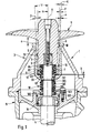
- the bottom of the propeller 5, i.e. the lower edge of the propeller blades is with Distance a above the upper free edge of the cup-shaped Housing recess 3 arranged.
- the hub 6 extends from the Side facing away from the propeller into the pot-shaped recess 3 and extends to the area of the bottom of the housing recess 3. That of the propeller facing end of the hub 6 is a short distance, distance b, arranged from the bottom of the housing recess 3.
- the hub 6 there is a coaxial on the end facing away from the propeller 5 cylindrical recess 7 arranged which has a cup-shaped receiving space forms, in which a seal 8 arranged on the shaft 4 engages.
- the medium preferably water, in which the agitator is used as a submersible agitator is formed, and the agitator by stirring by means of Propellers 5 is moved.
- the seal 8 forms a medium-side seal between the housing, ie between the seal housing 2 and hub 6 and shaft 4.
- the seal is designed as a mechanical seal. It has a slide ring 81, which is arranged in an angular sleeve 82 arranged in a stepped edge at the base of the housing recess 7, forming a sealing surface on the housing side.
- the slide ring 81 is made of ceramic material, for example silicon carbide. It surrounds the shaft 4, but remains fixed to the housing when the shaft 4 rotates, so that the shaft 4 thus slides in the fixed slide ring 81.
- a slide ring 83 is supported on the slide ring 81 and also surrounds the shaft 4.
- the inner diameter of the slide ring 83 is significantly larger than the inner diameter of the slide ring 81 and as the outer diameter of the shaft 4.
- the slide ring 83 is made of the same material as the slide ring 81, ie also of ceramic material, for example silicon carbide.
- the slide ring 83 is rotatably connected to the hub 6.
- a rubber bellows 84 is provided as a connecting element, which is mounted on the shaft 4 and is supported with its one end on the slide ring 83 and with its other end on the inner base of the recess 7 in the hub, forming a hub-side sealing surface.
- the rubber bellows 84 is axially tensioned by a coil spring 85 surrounding the rubber bellows, so that it is pressed tightly and non-rotatably against the base in the recess 7 of the hub 6 with its one end and its other end face is axially pressed against the slide ring 83.
- the hub 6 is designed such that it tapers towards its end facing away from the propeller 5, so that the outside of the hub 6, ie the outer wall of the hub 6, is essentially conical.
- the inner wall of the pot-shaped recess 3 is also conical.
- annular gap 9 extends to upper exit end. Both the outside diameter and the The inner diameter of the annular gap increases over the course of the annular gap 9 from the inside to the outside. The outer diameter increases more than the inside diameter. The respective growth is even, preferably constant, over the course from the inside to the outside, so that the Cross section of the annular gap in the axial direction from the inside to the outside increases continuously.
- Fig. 1 the cone angle ⁇ of the hub 6, the cone angle ⁇ of the cup-shaped Housing recess 3 and the cone angle ⁇ of the conical extension of the Annular gap 9 shown.
- the angle ⁇ is the angle that the central axis A forms the hub 6 with the outer wall of the hub 6, the legs of the angle ⁇ lie in a sectional plane in which the axis A lies.
- ⁇ is 1 °.
- the angle ⁇ is the angle that the central aligned with the central axis A of the hub 6 Axis of the housing recess 3 with the inner wall of the Housing recess 3 forms, the legs of the angle ⁇ in one Section plane in which the axis A lies.
- the angle ⁇ lies at that in Fig.
- the angle ⁇ is the angle of the conical expansion of the annular gap 9, wherein the angle ⁇ between the Outer wall of the hub 6 and the inner wall of the housing recess 3 is formed, the legs of the angle ⁇ lie in a sectional plane, in which is the axis A.
- the angle ⁇ is that shown in FIG. 1 Embodiment at 2 °.
- the principle of the constructive structure as the embodiment in Fig. 1 can have the angles ⁇ , ⁇ and ⁇ have different values.
- the angle ⁇ can have a value have, which is in the range between 0.5 ° to 10 °.
- the angle ⁇ can be one Have a value that is in the range between 1 ° to 13 ° and the angle ⁇ can have a value that is in the range between 0.5 ° and 3 °.
- a spiral elevation 10 formed which, surrounding the hub spirally or helically, of the end of the hub facing away from the propeller to the underside of the Propellers 5 extends. These spiral around the outer peripheral surface the hub 6 extending elevation 10 is in cross section in the essentially rectangular elevation opposite the hub outer wall educated.
- the radial height y of the elevation increases along its course towards the propeller, so that between the radial outside of the elevation and the inner wall of the cup-shaped housing recess 3 in substantially constant gap with radial width x is formed.
- the cross-sectional width q of the Annular gap between the outer wall of the hub 6 and the inner wall the cup-shaped housing recess with the angle ⁇ in the axial direction towards the outside because the inner wall of the recess 3 is more conical is than the taper of the outer wall of the hub 6.
- the conicity of the spiral shape 10 is the same as the taper of the inner wall of the cup-shaped recess 3 of the housing, i.e. each with a cone angle ⁇ , see above that in the area of the spiral shape, the clear gap width x to the inner wall of the cup-shaped housing recess 3, as mentioned above, is constant.
- the cross-sectional width is q of the annular gap 9 on the output side at 3.5 mm.
- the radial height y of the spiral shape 10 is on the output side, i.e. in the area of Output of the annular gap 9 at least 3 mm. In the bottom area of the annular gap 9, the radial height y is correspondingly lower.
- the distance x is constant over the entire axial length of the annular gap 9 and is included maximum 0.5 mm.
- the Distance x are in a range from 0.2 mm to 3 mm preferably constant at a selected value in this range.
- the radial height y of the spiral recess 10 can be in the range of 2 mm up to 10 mm.
- this is also modified Embodiments provided that the radial height y towards the propeller increases, i.e. has its maximum height in the area near the propeller.
- the Cross-sectional width q of the annular gap 9 can in this modified embodiment in a range between 2.2 mm to 13 mm lie.
- Cross-sectional width q of the annular gap 9 is preferably not constant about the axial extent of the gap, but the cross-sectional width q increases towards the propeller, i.e. to the exit of the gap 9 towards the formation of the Angle ⁇ to.
- the spiral shape 10 in connection with the annular gap 9 forms one Flow control device, the one when the propeller 5 rotates with the hub flow away from the seal 8 in the cup-shaped Formed housing 3 with which a deposit of particles in the Medium in the area of the seal or in the area of the bottom of the cup-shaped Housing shape 3 is counteracted. That the one rotating in the gap 9 Hub with the spiral shape 10 produces one according to the principle a screw pump promoting effect that the medium together with the promotes possible deposits from the annular gap 9.
- the shaft 4 is with an electric motor, not shown in Fig. 1, if necessary via an intermediate gearbox, in terms of drive connected.
- the shaft 4 can also directly as the Engine output shaft to be formed.
- the motor, not shown, is in the Housing stored in a section, the so-called motor housing 15th is trained.
- the upper portion of this motor housing 15 is in FIG. 1 shown.
- a rotary bearing 16 is supported, in which the the bearing through shaft 4 is rotatably supported.
- a mechanical seal 18 is present.
- the mechanical seal 18 is constructed in the same way as the mechanical seal 8 one with the motor housing via an angular sleeve 182 rotatably arranged ceramic slide ring 181 and one rotatably with the shaft 4 ceramic slide ring 183, which is non-rotatable with the shaft 4
- Rubber bellows 184 by means of a rubber bellows 184 surrounding Coil spring 185 is acted upon.
- the rubber bellows 184 with the Coil spring 185 is axially supported on two washers 186 which a snap ring 188 received in a radial groove 187 in turn are axially supported.
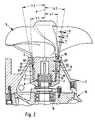
- Fig. 2 is an embodiment of an agitator with a larger propeller shown.
- the agitator is constructed in the same way as in the exemplary embodiment in Fig. 1, but the propeller 5 is larger and different is shaped in terms of size and shape of the propeller blades and in terms of Diameter and design of the hub 6.
- the hub 6 has two axially successively arranged sections of different conicity.
- the Cone angle ⁇ between the central axis A and the outer wall of the Hub 6 is therefore of different sizes in these two sections, namely in In the section 61 remote from the propeller, this angle ⁇ 1 is 2 ° and in the axially adjoining portion 62 near the propeller lies the angle ⁇ 2 at 9 °.
- the cup-shaped housing recess 3 is correspondingly educated. It has a section 31 near the bottom, the smaller one Has taper as the output section 32.
- the cone angle ⁇ 1 of the bottom-side section 31 is 3 ° in the exemplary embodiment in FIG. 2.
- the cone angle ⁇ 2 of the axially adjoining section 32 which extends up to extends to the exit of the cup-shaped formation 3, is in the illustrated embodiment 10 °. It follows that the between the outer wall of the hub 6 and the inner wall of the Housing recess 10 formed annular gap 9 also two axially has sections 91, 92 arranged one behind the other. You take each to the propeller and that section 91 of the annular gap 9 with the Angle ⁇ 1 and the section 92 with the angle ⁇ 2.
- the angles ⁇ 1 and ⁇ 2 are each the same. They are 1 °.
- the radial height y of the spiral shape 10 is in the range of Output of the annular gap 9 at 4 mm.
- the radial height y from end remote from the propeller towards the end near the propeller. This increase is so dimensioned that the radial width x of the clear gap between the Outside of the spiral elevation 10 and the inner wall of the Housing recess 3 over the entire axial extent of the annular Gap 9 is constant. In the case of the exemplary embodiment in FIG. 2, this is Distance x constant 1 mm.
- modified embodiments that are the same in principle constructive structure as the embodiment in Fig. 2 can have the cone angles ⁇ 1 and ⁇ 2 of the hub 6 and the cone angles ⁇ 1 and ⁇ 2 of the Housing recess 3 have other values.
- the cone angle ⁇ 1 is included these embodiments preferably at a value between 0.5 ° to 10 ° and the cone angle ⁇ 2 each larger and at a value up to 15 °.
- the cone angle ⁇ 1 of the housing configuration 3 is preferably in one Range from 1 ° to 13 ° and the consumption angle ⁇ 2 correspondingly larger preferably in a range up to 18 °.
- the radial width q of the annular gap 9 can preferably 2.2 mm to 13 mm in these embodiments lie.
- the radial height y of the spiral elevation 10 can preferably are in the range between 2 mm to 10 mm and preferably also increasingly towards the propeller.
- the distance x between the outside of the spiral elevation 10 and the inner wall of the housing formation 3 is also preferred in these modified exemplary embodiments constant. This constant distance x is preferably between values 0.2 mm to 3 mm.
- the outer wall of the hub 6 also not conical, i.e. e.g. be cylindrical. It can be in Difference to the embodiments in Figures 1 and 2, in which the Inner wall of the cup-shaped recess 3 or the two axial Sections 31, 32 of the cup-shaped housing recess 3 of the housing as Wall is formed without any elevations or depressions, also be provided that a spiral shape also on the Inner surface of the cup-shaped recess 3 is formed. Can also alternatively or in addition to the spiral elevations on the Outer wall of the hub or on the inner wall of the cup-shaped Recess as spiral formations also corresponding grooves wall in question.
- a pump specifically a submersible pump, which is also placed under water.
- she has a motor-driven shaft 40, on the drive side free end of an impeller 50 with hub 60 is rotatably arranged.
- the shaft 40 is a in the same way as in the embodiment in Fig. 1 Pot-shaped shape 30 of a seal housing in the Housing 10 of the pump mounted.
- a conical expanding annular gap space 90 is formed between the inner wall of the pot-shaped Formation 30 and the outside of the hub 60.
- the taper is Inner wall of the cup-shaped housing recess 30 stronger than that Taper of the hub 60 and the radial height of the spiral elevation 100 also takes off from the front of the hub during its spiral course towards the bottom of the impeller 50, thus has the same taper as that Inner wall of the housing formation 30, so that the gap area between the radial outside of the elevation 100 and the inside wall the cup-shaped shape 30 remains constant, but the rest clear cross section of the annular gap towards the exit end, i.e. in Direction to the impeller 50 increases.
- the spiral shape 100 in the outer circumference of the hub 60 causes Rotation of shaft 40 with impeller 50 with hub 60 one from the seal 80 directed flow in the annular gap 90, which from the annular gap 90 leads to a build-up of particles in the medium in the area the seal 80 is counteracted.
- the cup-shaped housing shape 30 can run in the conveying direction be provided on the housing side grooves, which promote the removal of the foreign body to the effect that they turn the same on the hub prevent.
- These grooves are preferably axially directed, i.e. parallel to Wheel hub.
- Several such grooves can be provided, preferably evenly distributed over the circumference, e.g. 4 hubs each 90 ° to each other added. However, only one such groove can also be provided, axially or spiraling.
- Modified exemplary embodiments are also provided, in which it are pumps in which an agitator, for example with the structure of that shown in FIGS. 1 and 2 Embodiments is used. These are so-called Recirculation pumps.
- the agitator used here is like this arranged that the propeller 5 is arranged in a pump housing in the interior of which projects the propeller 5.
- the interior of the Pump housing is filled with the pump medium, in which Pump interior on one side the supply line and on the other side the discharge on the pressure side opens.
- the performance of one such a recirculation pump is different from a pump with impeller, e.g. is shown in Fig.
Landscapes
- Engineering & Computer Science (AREA)
- General Engineering & Computer Science (AREA)
- Mechanical Engineering (AREA)
- Structures Of Non-Positive Displacement Pumps (AREA)
- Mechanical Sealing (AREA)
- Sealing Using Fluids, Sealing Without Contact, And Removal Of Oil (AREA)
- Sealing Of Bearings (AREA)
Abstract
Description
- Fig. 1
- eine Schnittansicht eines Rührwerks im Bereich des Propellers und des Dichtungsgehäuses;
- Fig. 2
- eine Fig. 1 entsprechende Schnittansicht eines Rührwerks mit größerem Propeller;
- Fig. 3
- eine Schnittansicht einer Pumpe im Bereich des Laufrads und des Dichtungsgehäuses.
Die Nabe 6 ist so ausgebildet, daß sie sich zu ihrem von dem Propeller 5 abgewandten Stirnende hin verjüngt, so daß die Außenseite der Nabe 6, d.h. die Außenwandung der Nabe 6 im wesentlichen konisch ist. Ebenfalls konisch ist die Innenwandung der topfförmigen Ausnehmung 3.
Claims (14)
- Maschine, vorzugsweise Strömungsmaschine, z.B. Pumpe, Rührwerk oder dergleichen,
mit einem stationären Gehäuse (1, 2, 20),
mit einer in dem Gehäuse gelagerten, motorisch angetriebenen Welle (4, 40) mit einem vorzugsweise drehfest verbundenen, ein fluides Medium bewegenden Rad, insbesondere Laufrad (50), Propeller (5) oder dergleichen,
wobei die Welle (4, 40) eine topfförmige Gehäuseausnehmung (3, 30) koaxial durchgreift und das am freien Ende der Welle (4, 40) angeordnete Rad (5, 50) außerhalb des Gehäuses (2, 20) angeordnet ist und dabei die auf der Welle (4, 40) angeordnete Nabe (6, 60) des Rads in die topfförmige Gehäuseausnehmung (3, 30) eingreift unter Ausbildung eines ringförmigen Spalts (9, 90) zwischen der Innenwandung der topfförmigen Gehäuseausnehmung (3, 30) und der Außenwandung der Nabe (6, 60), mit einer die Welle (4, 40) und/oder die Nabe (6, 60) und das Gehäuse zum Medium hin abdichtenden Dichtung (8, 80) und einer im Bereich der Nabe (6, 60) drehfest mit dieser angeordneten Spiraleinrichtung (10, 100), um zur Verhinderung einer Ablagerung von Partikeln eine in dem ringförmigen Spalt (9, 90) aus diesem herausgerichtete Strömung zu erzeugen,
dadurch gekennzeichnet, daß der Außendurchmesser und/oder der Querschnitt des ringförmigen Spalts (9, 90) zwischen der Innenwandung der topfförmigen Gehäuseausnehmung (3, 30) und der Außenwandung der Radnabe (6, 60) in seinem Verlauf zu dem Rad (5, 50) hin zunehmend ausgebildet ist bzw. sind. - Maschine nach Anspruch 1,
dadurch gekennzeichnet, daß die Spiraleinrichtung (10, 100) durch eine spiralförmig verlaufende Nut und/oder spiralförmig verlaufende Erhebung (10, 100) in der äußeren Umfangsfläche der Radnabe (6, 60) ausgebildet ist, vorzugsweise als spiralförmige Profilierung der Außenwandung der Radnabe, und
daß die radiale Höhe der spiralförmig verlaufenden Erhebung (10, 100) während ihres Verlaufs zum Rad (5, 50) hin zunehmend ausgebildet ist. - Maschine nach Anspruch 2,
dadurch gekennzeichnet, daß die radiale Außenwand der spiralförmig verlaufenden Erhebung (10, 100) während ihres Verlaufs konstanten Abstand zur Innenwandung der topfförmigen Ausnehmung (3, 30) des Gehäuses (2, 20) aufweist. - Maschine nach einem der vorangehenden Ansprüche,
dadurch gekennzeichnet, daß die Außenwandung der Radnabe (6, 60) konisch ausgebildet ist und
daß die Innenwandung der topfförmigen Gehäuseausnehmung (3, 30) konisch ausgebildet ist, und
daß ein die Konizität der Radnabe (6, 60) bestimmender Konuswinkel (α) kleiner ist als ein die Konizität der topfförmigen Gehäuseausnehmung (3, 30) bestimmender Konuswinkel (γ). - Maschine nach Anspruch 4,
dadurch gekennzeichnet, daß ein die Konizität der Radnabe (6,60) bestimmender Konuswinkel (α) auf verschiedenen axialen Abschnitten (61, 62) der Radnabe (6, 60) unterschiedlich groß ausgebildet ist. - Maschine nach einem der Ansprüche 4 oder 5,
dadurch gekennzeichnet, daß ein die Konizität der topfförmigen Gehäuseausnehmung (3, 30) bestimmender Konuswinkel (γ) auf verschiedenen axialen Abschnitten (31, 32) der topfförmigen Gehäuseausformung (3, 30) unterschiedlich groß ausgebildet ist, vorzugsweise in Abhängigkeit von dem die Konizität der Radnabe (6, 60) bestimmenden Konuswinkel (α), z.B. unter Ausbildung eines sich kontinuierlich erweiternden Spalts (9, 90, β). - Maschine nach dem Oberbegriff des Anspruchs 1, vorzugsweise i.V. mit einem der vorangehenden Ansprüche
dadurch gekennzeichnet, daß die Radnabe (6, 60) eine an der vom Rad (5, 50) abgewandten Stirnseite hin offene koaxiale Ausnehmung (7, 70) aufweist, in der zumindest ein Teil der Dichtung angeordnet ist,
wobei die Dichtung (8, 80) einen eine gehäuseseitige Dichtfläche aufweisenden gehäusefesten Gleitring (81, 181) aufweist, der im Bereich einer von der Welle (4, 40) durchsetzten Gehäuseöffnung angeordnet ist, und
wobei die Dichtung einen eine wellenseitige und/oder nabenseitige Dichtfläche aufweisenden mit der Welle (4, 40) bzw. Nabe (6, 60) drehfesten Gleitring (83, 183) aufweist, der innerhalb der Ausnehmung (7, 70) der Nabe (6, 60) angeordnet ist und/oder mit einem eine wellenseitige und/oder nabenseitige Dichtfläche aufweisenden elastischem Dichtelement (84, 184) zusammenwirkt, das innerhalb der Ausnehmung (7, 70) der Nabe (6, 60) angeordnet ist. - Rad, als Laufrad (50) oder Propeller (5) ausgebildet, vorzugsweise zum Einsatz in einer Strömungsmaschine, z.B. Pumpe, Rührwerk oder dergleichen,
mit Propellerflügeln bzw. Laufradschaufeln und mit einer Radnabe, vorzugsweise im Eingriff in eine topfförmige Gehäuseausnehmung (3, 30), insbesondere eines Dichtungsgehäuses (2) der Strömungsmaschine,
dadurch gekennzeichnet, daß die Radnabe (6, 60) einstückig mit den Propellerflügeln bzw. Laufradschaufeln verbunden ist und auf ihrer Außenwandung eine Spiraleinrichtung (10) aufweist. - Rad, als Laufrad (50) oder Propeller (5) ausgebildet, vorzugsweise zum Einsatz in einer Strömungsmaschine, z.B. Pumpe, Rührwerk oder dergleichen,
mit Propellerflügeln bzw. Laufradschaufeln und mit einer Radnabe, vorzugsweise im Eingriff in eine topfförmige Gehäuseausnehmung (3, 30), insbesondere eines Dichtungsgehäuses (2) der Strömungsmaschine, vorzugsweise nach Anspruch 8,
dadurch gekennzeichnet, daß die Spiraleinrichtung (10, 100) sich an der Außenseite der Radnabe (6, 60) von einer von den Propellerflügeln bzw. Radschaufeln entfernten Position auf der Radnabe, vorzugsweise von dem von den Propellerflügeln bzw. Radschaufeln entferntem Stirnende der Radnabe (6, 60) bis zur Unterseite der Propellerflügel bzw. Radschaufeln hin erstreckt. - Rad nach einem der Ansprüche 8 oder 9,
dadurch gekennzeichnet, daß die Spiraleinrichtung (10, 100) durch eine spiralförmig verlaufende Nut und/oder spiralförmig verlaufende Erhebung (10, 100) in der äußeren Umfangsfläche der Radnabe (6, 60) ausgebildet ist, vorzugsweise als spiralförmige Profilierung der Außenwandung der Radnabe (6, 60), wobei vorzugsweise vorgesehen ist, daß die radiale Höhe (y) der Erhebung (10, 100) in einem Größenbereich von 2 mm bis 10 mm liegt, insbesondere in einem Größenbereich um 3 mm, vorzugsweise bei einem Durchmesser der Radnabe von 30 bis 50 mm oder in einem Größenbereich von 4 mm, vorzugsweise bei einem Durchmesser der Radnabe von 50 bis 90 mm. - Rad nach Anspruch 10,
dadurch gekennzeichnet, daß die radiale Höhe (y) der spiralförmig verlaufenden Erhebung (10, 100) während ihres Verlaufs zu den Propellerflügeln bzw. Radschaufeln hin zunehmend groß ausgebildet ist. - Rad nach einem der Ansprüche 10 oder 11,
dadurch gekennzeichnet, daß die Außenwandung der Radnabe (6, 60) konisch ausgebildet ist, und daß ein die Konizität der Radnabe (6, 60) bestimmender Konuswinkel (α) auf verschiedenen axialen Abschnitten (61, 62) der Radnabe (6, 60) unterschiedlich groß ausgebildet ist. - Rad nach einem der Ansprüche 10 bis 12,
dadurch gekennzeichnet, daß die Radnabe (6, 60) an ihrem von den Propellerflügeln bzw. Radschaufeln entfernten Stirnende eine nach außen offene koaxiale Ausnehmung, vorzugsweise zur drehfesten Aufnahme eines Wellenendes und/oder zur Aufnahme einer Dichtungseinrichtung aufweist. - Rad nach einem der Ansprüche 10 bis 13,
dadurch gekennzeichnet, daß die Radnabe (6, 60) in dem Bereich, in dem die Propellerflügel angeordnet, vorzugsweise angeformt sind, eine Verdickung des Nabenaußendurchmessers aufweist, und
daß die Verdickung der Radnabe als ein verdickter axialer Abschnitt der Radnabe ausgebildet ist, der im wesentlichen kugelförmig oder zylinderförmig ausgebildet ist, und
daß zwischen der Verdickung bzw. dem verdickten Abschnitt der Radnabe (6, 60) und dem daran anschließenden axialen Abschnitt der Radnabe (6, 60) ein Übergangsbereich ausgebildet ist, der abgeschrägt oder abgerundet oder stufenförmig ausgebildet ist, und
daß die Radnabe im Bereich der Verdickung bzw. des verdickten axialen Abschnitts ihren größten Außendurchmesser aufweist.
Applications Claiming Priority (4)
| Application Number | Priority Date | Filing Date | Title |
|---|---|---|---|
| DE10060617 | 2000-12-05 | ||
| DE10060617 | 2000-12-05 | ||
| DE10103575 | 2001-01-27 | ||
| DE10103575A DE10103575B4 (de) | 2000-12-05 | 2001-01-27 | Strömungsarbeitsmaschine, z.B. Pumpe oder Rührwerk |
Publications (4)
| Publication Number | Publication Date |
|---|---|
| EP1213517A2 true EP1213517A2 (de) | 2002-06-12 |
| EP1213517A3 EP1213517A3 (de) | 2002-12-18 |
| EP1213517B1 EP1213517B1 (de) | 2005-11-09 |
| EP1213517B8 EP1213517B8 (de) | 2006-01-18 |
Family
ID=26007893
Family Applications (1)
| Application Number | Title | Priority Date | Filing Date |
|---|---|---|---|
| EP01128867A Expired - Lifetime EP1213517B8 (de) | 2000-12-05 | 2001-12-05 | Gleitringdichtung für Strömungsmaschinen |
Country Status (5)
| Country | Link |
|---|---|
| US (1) | US6612805B2 (de) |
| EP (1) | EP1213517B8 (de) |
| JP (1) | JP2002228012A (de) |
| AT (1) | ATE309494T1 (de) |
| DE (1) | DE50107975D1 (de) |
Cited By (1)
| Publication number | Priority date | Publication date | Assignee | Title |
|---|---|---|---|---|
| WO2016055302A1 (de) * | 2014-10-07 | 2016-04-14 | Ksb Aktiengesellschaft | Rührwerk |
Families Citing this family (13)
| Publication number | Priority date | Publication date | Assignee | Title |
|---|---|---|---|---|
| US7732451B2 (en) | 2001-08-10 | 2010-06-08 | Palatin Technologies, Inc. | Naphthalene-containing melanocortin receptor-specific small molecule |
| CA2462200A1 (en) | 2001-08-10 | 2003-02-20 | Palatin Technologies, Inc. | Peptidomimetics of biologically active metallopeptides |
| US7718802B2 (en) | 2001-08-10 | 2010-05-18 | Palatin Technologies, Inc. | Substituted melanocortin receptor-specific piperazine compounds |
| US7655658B2 (en) | 2001-08-10 | 2010-02-02 | Palatin Technologies, Inc. | Thieno [2,3-D]pyrimidine-2,4-dione melanocortin-specific compounds |
| US7456184B2 (en) | 2003-05-01 | 2008-11-25 | Palatin Technologies Inc. | Melanocortin receptor-specific compounds |
| US7968548B2 (en) * | 2003-05-01 | 2011-06-28 | Palatin Technologies, Inc. | Melanocortin receptor-specific piperazine compounds with diamine groups |
| US7727991B2 (en) | 2003-05-01 | 2010-06-01 | Palatin Technologies, Inc. | Substituted melanocortin receptor-specific single acyl piperazine compounds |
| US7727990B2 (en) | 2003-05-01 | 2010-06-01 | Palatin Technologies, Inc. | Melanocortin receptor-specific piperazine and keto-piperazine compounds |
| US7709484B1 (en) | 2004-04-19 | 2010-05-04 | Palatin Technologies, Inc. | Substituted melanocortin receptor-specific piperazine compounds |
| US7834017B2 (en) | 2006-08-11 | 2010-11-16 | Palatin Technologies, Inc. | Diamine-containing, tetra-substituted piperazine compounds having identical 1- and 4-substituents |
| DE102022113278A1 (de) | 2022-05-25 | 2023-11-30 | KSB SE & Co. KGaA | Rührwerkanordnung |
| CN115158622B (zh) * | 2022-06-15 | 2023-05-23 | 中国船舶重工集团公司第七一九研究所 | 适应复杂水域的集成电机推进装置 |
| CN115569552B (zh) * | 2022-10-09 | 2023-07-25 | 南京科技职业学院 | 一种改善流场分布的潜水搅拌机 |
Citations (4)
| Publication number | Priority date | Publication date | Assignee | Title |
|---|---|---|---|---|
| EP0252037A1 (de) | 1986-06-27 | 1988-01-07 | Flygt AB | Dichtungsvorrichtung |
| EP0542530A1 (de) | 1991-11-11 | 1993-05-19 | Heliseal Pty Ltd | Abdichtung |
| EP0879977A2 (de) | 1997-05-23 | 1998-11-25 | Firma Carl Freudenberg | Dichtungsanordnung |
| US6053500A (en) | 1996-05-15 | 2000-04-25 | Itt Flygt Ab | Seal housing |
Family Cites Families (6)
| Publication number | Priority date | Publication date | Assignee | Title |
|---|---|---|---|---|
| US2802679A (en) * | 1953-06-30 | 1957-08-13 | Nat Lead Co | Mechanical seal for pumps |
| GB975076A (en) | 1962-02-12 | 1964-11-11 | Asahi Chemical Ind | Shaft-seal for preventing leakage of highly viscous liquid |
| NL6713596A (de) | 1967-10-06 | 1969-04-09 | ||
| US4202654A (en) * | 1976-12-29 | 1980-05-13 | Marlow Alfred S | Wear resistant self lubricating centrifugal pump |
| DE3015211C2 (de) | 1980-04-19 | 1986-05-28 | Klein, Schanzlin & Becker Ag, 6710 Frankenthal | Schutzeinrichtung für Unterwassermotoren |
| AU3690697A (en) | 1996-08-05 | 1998-02-25 | A.W. Chesterton Company | Seal/bearing assembly |
-
2001
- 2001-11-27 US US09/994,478 patent/US6612805B2/en not_active Expired - Lifetime
- 2001-12-05 AT AT01128867T patent/ATE309494T1/de active
- 2001-12-05 EP EP01128867A patent/EP1213517B8/de not_active Expired - Lifetime
- 2001-12-05 JP JP2001371724A patent/JP2002228012A/ja active Pending
- 2001-12-05 DE DE50107975T patent/DE50107975D1/de not_active Expired - Lifetime
Patent Citations (4)
| Publication number | Priority date | Publication date | Assignee | Title |
|---|---|---|---|---|
| EP0252037A1 (de) | 1986-06-27 | 1988-01-07 | Flygt AB | Dichtungsvorrichtung |
| EP0542530A1 (de) | 1991-11-11 | 1993-05-19 | Heliseal Pty Ltd | Abdichtung |
| US6053500A (en) | 1996-05-15 | 2000-04-25 | Itt Flygt Ab | Seal housing |
| EP0879977A2 (de) | 1997-05-23 | 1998-11-25 | Firma Carl Freudenberg | Dichtungsanordnung |
Cited By (1)
| Publication number | Priority date | Publication date | Assignee | Title |
|---|---|---|---|---|
| WO2016055302A1 (de) * | 2014-10-07 | 2016-04-14 | Ksb Aktiengesellschaft | Rührwerk |
Also Published As
| Publication number | Publication date |
|---|---|
| US6612805B2 (en) | 2003-09-02 |
| EP1213517A3 (de) | 2002-12-18 |
| ATE309494T1 (de) | 2005-11-15 |
| DE50107975D1 (de) | 2005-12-15 |
| US20020071761A1 (en) | 2002-06-13 |
| EP1213517B8 (de) | 2006-01-18 |
| JP2002228012A (ja) | 2002-08-14 |
| EP1213517B1 (de) | 2005-11-09 |
Similar Documents
| Publication | Publication Date | Title |
|---|---|---|
| EP1213517B1 (de) | Gleitringdichtung für Strömungsmaschinen | |
| DE69106631T2 (de) | Drehpumpe. | |
| DE4232936C2 (de) | Impeller zum Rühren von sterilen Flüssigkeiten | |
| EP2888484B1 (de) | Pumpe zum fördern von abwasser sowie laufrad und bodenplatte für eine solche | |
| DE1528763A1 (de) | Kreiselpumpe | |
| DE1800888A1 (de) | Pumpendichtung | |
| EP2188532B1 (de) | Pumpenlaufrad und pumpe umfassend ein derartiges pumpenlaufrad | |
| DE2313403A1 (de) | Axial-stroemungsmaschine | |
| EP3779201B1 (de) | Abstreifelement für laufradeintrittskanten von abwasserpumpen | |
| EP3478389B1 (de) | Rückspülfilter | |
| DE4428633A1 (de) | Kraftstoffpumpe zum Zuführen von Kraftstoff zu einem Fahrzeugmotor | |
| EP0734776A1 (de) | Rotordüse, insbesondere für Hochdruckreinigungsgerät | |
| DE602004004309T2 (de) | Schraubenpumpe | |
| DE10155547A1 (de) | Zentrifugalpumpe | |
| DE10103575A1 (de) | Maschine,vorzugsweise Strömungsmaschine, z.B. Pumpe, Rührwerk oder dergleichen | |
| DE102008057849A1 (de) | Schneidvorrichtung einer Pumpe | |
| DE4340193A1 (de) | Saugeinheit für dentale Zwecke | |
| EP2497956A1 (de) | Freistrompumpe | |
| DE4239071C2 (de) | Tauchpumpenaggregat | |
| DE3341857A1 (de) | Kegelbrecher | |
| DE3732038A1 (de) | Pumpe | |
| DE60217638T2 (de) | Kreiselpumpenlaufrad | |
| DE1653802B2 (de) | Pumpe zum foerdern von faserigen, dickfluessigen fluessigkeiten, wie mist, mit hohem gehalt an trockenmasse | |
| WO2012152599A1 (de) | Pumpenaggregat | |
| DE2442446A1 (de) | Pumpe zum foerdern von wasser und abwasser |
Legal Events
| Date | Code | Title | Description |
|---|---|---|---|
| PUAI | Public reference made under article 153(3) epc to a published international application that has entered the european phase |
Free format text: ORIGINAL CODE: 0009012 |
|
| AK | Designated contracting states |
Kind code of ref document: A2 Designated state(s): AT BE CH CY DE DK ES FI FR GB GR IE IT LI LU MC NL PT SE TR |
|
| AX | Request for extension of the european patent |
Free format text: AL;LT;LV;MK;RO;SI |
|
| PUAL | Search report despatched |
Free format text: ORIGINAL CODE: 0009013 |
|
| AK | Designated contracting states |
Kind code of ref document: A3 Designated state(s): AT BE CH CY DE DK ES FI FR GB GR IE IT LI LU MC NL PT SE TR |
|
| AX | Request for extension of the european patent |
Free format text: AL;LT;LV;MK;RO;SI |
|
| 17P | Request for examination filed |
Effective date: 20030506 |
|
| AKX | Designation fees paid |
Designated state(s): AT BE CH CY DE DK ES FI FR GB GR IE IT LI LU MC NL PT SE TR |
|
| 17Q | First examination report despatched |
Effective date: 20040521 |
|
| GRAP | Despatch of communication of intention to grant a patent |
Free format text: ORIGINAL CODE: EPIDOSNIGR1 |
|
| GRAS | Grant fee paid |
Free format text: ORIGINAL CODE: EPIDOSNIGR3 |
|
| GRAA | (expected) grant |
Free format text: ORIGINAL CODE: 0009210 |
|
| AK | Designated contracting states |
Kind code of ref document: B1 Designated state(s): AT BE CH CY DE DK ES FI FR GB GR IE IT LI LU MC NL PT SE TR |
|
| PG25 | Lapsed in a contracting state [announced via postgrant information from national office to epo] |
Ref country code: IT Free format text: LAPSE BECAUSE OF FAILURE TO SUBMIT A TRANSLATION OF THE DESCRIPTION OR TO PAY THE FEE WITHIN THE PRESCRIBED TIME-LIMIT;WARNING: LAPSES OF ITALIAN PATENTS WITH EFFECTIVE DATE BEFORE 2007 MAY HAVE OCCURRED AT ANY TIME BEFORE 2007. THE CORRECT EFFECTIVE DATE MAY BE DIFFERENT FROM THE ONE RECORDED. Effective date: 20051109 Ref country code: TR Free format text: LAPSE BECAUSE OF FAILURE TO SUBMIT A TRANSLATION OF THE DESCRIPTION OR TO PAY THE FEE WITHIN THE PRESCRIBED TIME-LIMIT Effective date: 20051109 Ref country code: FI Free format text: LAPSE BECAUSE OF FAILURE TO SUBMIT A TRANSLATION OF THE DESCRIPTION OR TO PAY THE FEE WITHIN THE PRESCRIBED TIME-LIMIT Effective date: 20051109 Ref country code: GB Free format text: LAPSE BECAUSE OF FAILURE TO SUBMIT A TRANSLATION OF THE DESCRIPTION OR TO PAY THE FEE WITHIN THE PRESCRIBED TIME-LIMIT Effective date: 20051109 Ref country code: NL Free format text: LAPSE BECAUSE OF FAILURE TO SUBMIT A TRANSLATION OF THE DESCRIPTION OR TO PAY THE FEE WITHIN THE PRESCRIBED TIME-LIMIT Effective date: 20051109 Ref country code: IE Free format text: LAPSE BECAUSE OF FAILURE TO SUBMIT A TRANSLATION OF THE DESCRIPTION OR TO PAY THE FEE WITHIN THE PRESCRIBED TIME-LIMIT Effective date: 20051109 |
|
| REG | Reference to a national code |
Ref country code: GB Ref legal event code: FG4D Free format text: NOT ENGLISH |
|
| RTI1 | Title (correction) |
Free format text: MECHANICAL SEAL FOR FLUID-FLOW MACHINES |
|
| REG | Reference to a national code |
Ref country code: CH Ref legal event code: EP |
|
| PG25 | Lapsed in a contracting state [announced via postgrant information from national office to epo] |
Ref country code: CY Free format text: LAPSE BECAUSE OF FAILURE TO SUBMIT A TRANSLATION OF THE DESCRIPTION OR TO PAY THE FEE WITHIN THE PRESCRIBED TIME-LIMIT Effective date: 20051205 |
|
| REG | Reference to a national code |
Ref country code: IE Ref legal event code: FG4D Free format text: LANGUAGE OF EP DOCUMENT: GERMAN |
|
| REF | Corresponds to: |
Ref document number: 50107975 Country of ref document: DE Date of ref document: 20051215 Kind code of ref document: P |
|
| PG25 | Lapsed in a contracting state [announced via postgrant information from national office to epo] |
Ref country code: MC Free format text: LAPSE BECAUSE OF NON-PAYMENT OF DUE FEES Effective date: 20051231 Ref country code: LI Free format text: LAPSE BECAUSE OF NON-PAYMENT OF DUE FEES Effective date: 20051231 Ref country code: CH Free format text: LAPSE BECAUSE OF NON-PAYMENT OF DUE FEES Effective date: 20051231 |
|
| RAP2 | Party data changed (patent owner data changed or rights of a patent transferred) |
Owner name: WILO AG |
|
| PG25 | Lapsed in a contracting state [announced via postgrant information from national office to epo] |
Ref country code: LU Free format text: LAPSE BECAUSE OF NON-PAYMENT OF DUE FEES Effective date: 20060109 |
|
| PG25 | Lapsed in a contracting state [announced via postgrant information from national office to epo] |
Ref country code: DK Free format text: LAPSE BECAUSE OF FAILURE TO SUBMIT A TRANSLATION OF THE DESCRIPTION OR TO PAY THE FEE WITHIN THE PRESCRIBED TIME-LIMIT Effective date: 20060209 Ref country code: SE Free format text: LAPSE BECAUSE OF FAILURE TO SUBMIT A TRANSLATION OF THE DESCRIPTION OR TO PAY THE FEE WITHIN THE PRESCRIBED TIME-LIMIT Effective date: 20060209 Ref country code: GR Free format text: LAPSE BECAUSE OF FAILURE TO SUBMIT A TRANSLATION OF THE DESCRIPTION OR TO PAY THE FEE WITHIN THE PRESCRIBED TIME-LIMIT Effective date: 20060209 |
|
| PG25 | Lapsed in a contracting state [announced via postgrant information from national office to epo] |
Ref country code: ES Free format text: LAPSE BECAUSE OF FAILURE TO SUBMIT A TRANSLATION OF THE DESCRIPTION OR TO PAY THE FEE WITHIN THE PRESCRIBED TIME-LIMIT Effective date: 20060220 |
|
| NLT2 | Nl: modifications (of names), taken from the european patent patent bulletin |
Owner name: WILO AG Effective date: 20060104 |
|
| PG25 | Lapsed in a contracting state [announced via postgrant information from national office to epo] |
Ref country code: PT Free format text: LAPSE BECAUSE OF FAILURE TO SUBMIT A TRANSLATION OF THE DESCRIPTION OR TO PAY THE FEE WITHIN THE PRESCRIBED TIME-LIMIT Effective date: 20060410 |
|
| NLV1 | Nl: lapsed or annulled due to failure to fulfill the requirements of art. 29p and 29m of the patents act | ||
| GBV | Gb: ep patent (uk) treated as always having been void in accordance with gb section 77(7)/1977 [no translation filed] |
Effective date: 20051109 |
|
| ET | Fr: translation filed | ||
| REG | Reference to a national code |
Ref country code: IE Ref legal event code: FD4D |
|
| REG | Reference to a national code |
Ref country code: CH Ref legal event code: PL |
|
| PLBE | No opposition filed within time limit |
Free format text: ORIGINAL CODE: 0009261 |
|
| STAA | Information on the status of an ep patent application or granted ep patent |
Free format text: STATUS: NO OPPOSITION FILED WITHIN TIME LIMIT |
|
| 26N | No opposition filed |
Effective date: 20060810 |
|
| REG | Reference to a national code |
Ref country code: HK Ref legal event code: WD Ref document number: 1045554 Country of ref document: HK |
|
| PGFP | Annual fee paid to national office [announced via postgrant information from national office to epo] |
Ref country code: AT Payment date: 20141215 Year of fee payment: 14 |
|
| PGFP | Annual fee paid to national office [announced via postgrant information from national office to epo] |
Ref country code: BE Payment date: 20141211 Year of fee payment: 14 |
|
| REG | Reference to a national code |
Ref country code: FR Ref legal event code: PLFP Year of fee payment: 15 |
|
| PG25 | Lapsed in a contracting state [announced via postgrant information from national office to epo] |
Ref country code: BE Free format text: LAPSE BECAUSE OF NON-PAYMENT OF DUE FEES Effective date: 20151231 |
|
| REG | Reference to a national code |
Ref country code: AT Ref legal event code: MM01 Ref document number: 309494 Country of ref document: AT Kind code of ref document: T Effective date: 20151205 |
|
| REG | Reference to a national code |
Ref country code: FR Ref legal event code: PLFP Year of fee payment: 16 |
|
| PG25 | Lapsed in a contracting state [announced via postgrant information from national office to epo] |
Ref country code: AT Free format text: LAPSE BECAUSE OF NON-PAYMENT OF DUE FEES Effective date: 20151205 |
|
| REG | Reference to a national code |
Ref country code: FR Ref legal event code: PLFP Year of fee payment: 17 |
|
| PGFP | Annual fee paid to national office [announced via postgrant information from national office to epo] |
Ref country code: FR Payment date: 20201120 Year of fee payment: 20 Ref country code: DE Payment date: 20201119 Year of fee payment: 20 |
|
| REG | Reference to a national code |
Ref country code: DE Ref legal event code: R071 Ref document number: 50107975 Country of ref document: DE |