EP0879977A2 - Dichtungsanordnung - Google Patents
Dichtungsanordnung Download PDFInfo
- Publication number
- EP0879977A2 EP0879977A2 EP98103078A EP98103078A EP0879977A2 EP 0879977 A2 EP0879977 A2 EP 0879977A2 EP 98103078 A EP98103078 A EP 98103078A EP 98103078 A EP98103078 A EP 98103078A EP 0879977 A2 EP0879977 A2 EP 0879977A2
- Authority
- EP
- European Patent Office
- Prior art keywords
- sealed
- sealing
- sealing arrangement
- groove
- arrangement according
- Prior art date
- Legal status (The legal status is an assumption and is not a legal conclusion. Google has not performed a legal analysis and makes no representation as to the accuracy of the status listed.)
- Granted
Links
Images
Classifications
-
- F—MECHANICAL ENGINEERING; LIGHTING; HEATING; WEAPONS; BLASTING
- F16—ENGINEERING ELEMENTS AND UNITS; GENERAL MEASURES FOR PRODUCING AND MAINTAINING EFFECTIVE FUNCTIONING OF MACHINES OR INSTALLATIONS; THERMAL INSULATION IN GENERAL
- F16J—PISTONS; CYLINDERS; SEALINGS
- F16J15/00—Sealings
- F16J15/16—Sealings between relatively-moving surfaces
- F16J15/34—Sealings between relatively-moving surfaces with slip-ring pressed against a more or less radial face on one member
- F16J15/3492—Sealings between relatively-moving surfaces with slip-ring pressed against a more or less radial face on one member with monitoring or measuring means associated with the seal
-
- F—MECHANICAL ENGINEERING; LIGHTING; HEATING; WEAPONS; BLASTING
- F16—ENGINEERING ELEMENTS AND UNITS; GENERAL MEASURES FOR PRODUCING AND MAINTAINING EFFECTIVE FUNCTIONING OF MACHINES OR INSTALLATIONS; THERMAL INSULATION IN GENERAL
- F16J—PISTONS; CYLINDERS; SEALINGS
- F16J15/00—Sealings
- F16J15/16—Sealings between relatively-moving surfaces
- F16J15/32—Sealings between relatively-moving surfaces with elastic sealings, e.g. O-rings
- F16J15/3248—Sealings between relatively-moving surfaces with elastic sealings, e.g. O-rings provided with casings or supports
- F16J15/3252—Sealings between relatively-moving surfaces with elastic sealings, e.g. O-rings provided with casings or supports with rigid casings or supports
- F16J15/3256—Sealings between relatively-moving surfaces with elastic sealings, e.g. O-rings provided with casings or supports with rigid casings or supports comprising two casing or support elements, one attached to each surface, e.g. cartridge or cassette seals
-
- F—MECHANICAL ENGINEERING; LIGHTING; HEATING; WEAPONS; BLASTING
- F16—ENGINEERING ELEMENTS AND UNITS; GENERAL MEASURES FOR PRODUCING AND MAINTAINING EFFECTIVE FUNCTIONING OF MACHINES OR INSTALLATIONS; THERMAL INSULATION IN GENERAL
- F16J—PISTONS; CYLINDERS; SEALINGS
- F16J15/00—Sealings
- F16J15/16—Sealings between relatively-moving surfaces
- F16J15/32—Sealings between relatively-moving surfaces with elastic sealings, e.g. O-rings
- F16J15/324—Arrangements for lubrication or cooling of the sealing itself
-
- F—MECHANICAL ENGINEERING; LIGHTING; HEATING; WEAPONS; BLASTING
- F16—ENGINEERING ELEMENTS AND UNITS; GENERAL MEASURES FOR PRODUCING AND MAINTAINING EFFECTIVE FUNCTIONING OF MACHINES OR INSTALLATIONS; THERMAL INSULATION IN GENERAL
- F16J—PISTONS; CYLINDERS; SEALINGS
- F16J15/00—Sealings
- F16J15/16—Sealings between relatively-moving surfaces
- F16J15/32—Sealings between relatively-moving surfaces with elastic sealings, e.g. O-rings
- F16J15/3244—Sealings between relatively-moving surfaces with elastic sealings, e.g. O-rings with hydrodynamic pumping action
-
- F—MECHANICAL ENGINEERING; LIGHTING; HEATING; WEAPONS; BLASTING
- F16—ENGINEERING ELEMENTS AND UNITS; GENERAL MEASURES FOR PRODUCING AND MAINTAINING EFFECTIVE FUNCTIONING OF MACHINES OR INSTALLATIONS; THERMAL INSULATION IN GENERAL
- F16J—PISTONS; CYLINDERS; SEALINGS
- F16J15/00—Sealings
- F16J15/16—Sealings between relatively-moving surfaces
- F16J15/34—Sealings between relatively-moving surfaces with slip-ring pressed against a more or less radial face on one member
- F16J15/3404—Sealings between relatively-moving surfaces with slip-ring pressed against a more or less radial face on one member and characterised by parts or details relating to lubrication, cooling or venting of the seal
-
- F—MECHANICAL ENGINEERING; LIGHTING; HEATING; WEAPONS; BLASTING
- F16—ENGINEERING ELEMENTS AND UNITS; GENERAL MEASURES FOR PRODUCING AND MAINTAINING EFFECTIVE FUNCTIONING OF MACHINES OR INSTALLATIONS; THERMAL INSULATION IN GENERAL
- F16J—PISTONS; CYLINDERS; SEALINGS
- F16J15/00—Sealings
- F16J15/16—Sealings between relatively-moving surfaces
- F16J15/34—Sealings between relatively-moving surfaces with slip-ring pressed against a more or less radial face on one member
- F16J15/3464—Mounting of the seal
-
- Y—GENERAL TAGGING OF NEW TECHNOLOGICAL DEVELOPMENTS; GENERAL TAGGING OF CROSS-SECTIONAL TECHNOLOGIES SPANNING OVER SEVERAL SECTIONS OF THE IPC; TECHNICAL SUBJECTS COVERED BY FORMER USPC CROSS-REFERENCE ART COLLECTIONS [XRACs] AND DIGESTS
- Y10—TECHNICAL SUBJECTS COVERED BY FORMER USPC
- Y10S—TECHNICAL SUBJECTS COVERED BY FORMER USPC CROSS-REFERENCE ART COLLECTIONS [XRACs] AND DIGESTS
- Y10S277/00—Seal for a joint or juncture
- Y10S277/908—Seal for use in rotating and reciprocating arrangement
-
- Y—GENERAL TAGGING OF NEW TECHNOLOGICAL DEVELOPMENTS; GENERAL TAGGING OF CROSS-SECTIONAL TECHNOLOGIES SPANNING OVER SEVERAL SECTIONS OF THE IPC; TECHNICAL SUBJECTS COVERED BY FORMER USPC CROSS-REFERENCE ART COLLECTIONS [XRACs] AND DIGESTS
- Y10—TECHNICAL SUBJECTS COVERED BY FORMER USPC
- Y10T—TECHNICAL SUBJECTS COVERED BY FORMER US CLASSIFICATION
- Y10T407/00—Cutters, for shaping
- Y10T407/17—Gear cutting tool
- Y10T407/1715—Hob
- Y10T407/172—Thread cutting
-
- Y—GENERAL TAGGING OF NEW TECHNOLOGICAL DEVELOPMENTS; GENERAL TAGGING OF CROSS-SECTIONAL TECHNOLOGIES SPANNING OVER SEVERAL SECTIONS OF THE IPC; TECHNICAL SUBJECTS COVERED BY FORMER USPC CROSS-REFERENCE ART COLLECTIONS [XRACs] AND DIGESTS
- Y10—TECHNICAL SUBJECTS COVERED BY FORMER USPC
- Y10T—TECHNICAL SUBJECTS COVERED BY FORMER US CLASSIFICATION
- Y10T82/00—Turning
- Y10T82/10—Process of turning
-
- Y—GENERAL TAGGING OF NEW TECHNOLOGICAL DEVELOPMENTS; GENERAL TAGGING OF CROSS-SECTIONAL TECHNOLOGIES SPANNING OVER SEVERAL SECTIONS OF THE IPC; TECHNICAL SUBJECTS COVERED BY FORMER USPC CROSS-REFERENCE ART COLLECTIONS [XRACs] AND DIGESTS
- Y10—TECHNICAL SUBJECTS COVERED BY FORMER USPC
- Y10T—TECHNICAL SUBJECTS COVERED BY FORMER US CLASSIFICATION
- Y10T82/00—Turning
- Y10T82/16—Severing or cut-off
Definitions
- the invention relates to a sealing arrangement according to the preamble of Claim 1 and a method for producing the surface to be sealed.
- Such a sealing arrangement and a method are, for example known from DE-OS 15 433.
- a return twist is one Provide the shaft with recesses that are oblique to the longitudinal axis, whereby the return twist at the location of the largest through the radial shaft seal pressure applied due to the associated change in shape and the associated wear has been removed after a short period of operation, so that no further wear of the sealing ring can occur. Immediately in the neighborhood of this extinguished return twist the existing grooves still have a positive effect. In the previously known document describes that a return thread would destroy the sealing edge of the radial shaft seal.
- the recesses are made by a simple piercing process, for example by rotating grinding wheels or with one Lubricating powder provided polishing disc.
- a disadvantage of surfaces is that it is not predictable whether the Sealing arrangement during its intended use will have sufficiently good sealing behavior.
- the honed Surface has an unpredictable number of helical running, differently deep, multi-start grooves, where the number and shape change during the manufacture of the surface the gears, depending on the condition of the grinding wheel, from the Vibration behavior of the drive shaft of the grinding wheel and / or the grinding surface and the spatial assignment of the axes of rotation always incalculably changed to each other.
- the volume of medium to be sealed within the grooves be so large that the Radial shaft sealing ring is no longer able to in the medium to be sealed to return the space to be sealed.
- the invention has for its object a sealing arrangement continue to develop in such a way that the machining-related twist on the surface is detectable and that the twist in its effects on the Leakage behavior of the radial shaft seals is quantifiable to failures the sealing arrangement due to an unfavorable Avoid surface texture.
- the surface should be like this be such that the radial shaft seal, regardless of the Direction of rotation of the machine element is able to lubricate the Sealing edge required volumes in the space to be sealed to return.
- a helical groove is screwed with a rounded groove base and that the groove base has a radius of curvature of 0.4 to 1.6 mm and the depth the groove is less than 15 ⁇ m.
- turned surfaces are much cheaper to produce.
- twist on the surface created by the turning detectable and its effects on the tightness behavior of the Radial shaft seals can be quantified. It is therefore possible to easy and inexpensive to check whether the turned surface was professionally manufactured and the required parameters were observed were.
- the rotated surface promotes this medium to be sealed more or less strongly in the axial direction on the Surface along.
- the radial shaft sealing ring With a radius of curvature of 0.4 to 1.6 mm and one Depth of the groove of less than 15 ⁇ m, the radial shaft sealing ring is able to regardless of the direction of rotation of the machine element for lubrication the volume of medium to be sealed in the sealing edge promote the space to be sealed.
- the return effect of the Radial shaft sealing rings are caused by the two conical surfaces, the the first conical surface facing the space to be sealed with the Axis of rotation includes a steeper cone angle than that second cone surface facing away.
- the depth of the groove is preferably at most 10 ⁇ m. By the lesser The depth of the groove is the operational wear on the sealing edge of the Radial shaft sealing rings lower, so that the invention Sealing arrangement further improved performance during has an even longer service life.
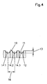
- the adjacent helix of the groove preferably have one Center distance from 0.03 to 0.3 mm. With center distances up to 0.3 mm is the swirl-related delivery of the medium to be sealed from the space to be sealed, regardless of the direction of rotation of the Machine element, in any case still so low that a secure seal is guaranteed by the radial shaft seal. Center distances from less than 0.03 mm makes little sense, since the processing of such Surface takes a comparatively long time and the metrological acquisition of the twist becomes significantly more difficult.
- the width of the sealing edge 1, 5 to 4 times is greater than the slope of the groove.
- the machine element can be a shaft or a race Cassette seal can be formed.
- the invention also relates to a method for producing the surface of a sealing arrangement to be sealed.
- the surface is fed with a feed of 0.03 to 0.3 mm, a cutting speed of 80 to 400 m / min. and a cutting depth of 0.04 to 0.4 mm.
- an average roughness R a according to DIN 4762 of 0.05 to 2 ⁇ m is achieved.
- the average roughness value R a is the arithmetic mean of the amounts of all profile values of the roughness profile.
- a roughness depth R z in accordance with DIN 4768 is achieved, which is 0.2 to 10 ⁇ m.
- the average roughness depth R z is the average of the individual roughness depths of successive individual measurement sections.
- the maximum roughness depth R max according to DIN 4768 is the greatest single roughness depth within the total measuring distance and is at most 15 ⁇ m in the method described above.
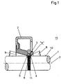
- Figure 1 is a first embodiment of a sealing arrangement shown, in which the machine element 1 by a shaft to be sealed formed and by a radial shaft seal 2 on the outer circumference is enclosed.
- the sealing lip 3 of the radial shaft sealing ring 2 has one Sealing edge 6, which by two intersecting conical surfaces 4, 5th is limited.
- the medium to be sealed is inside the room to be sealed, which is provided with the reference numeral 15.
- the first conical surface 4 facing the space 15 to be sealed also closes the axis of rotation 7 a first cone angle 8, which is larger than that second cone angle 9, the second cone surface 5 with the axis of rotation 7 limited.
- the sealing edge 6 touches the surface 10 under radial Prestressing sealing, the width of the sealing edge 6 being 1.5 to 4 times larger is than the slope of the groove 11, so that even when stationary Machine element 1 a good static seal is guaranteed.
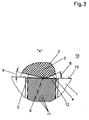
- the portion of the surface 10 which is the tread for the sealing edge 6 is provided with at least one helically extending groove 11, the has a rounded groove base 12, the groove base 12 having a Rounding radius from 0.4 to 1.6 mm, in this embodiment 1.0 mm having.
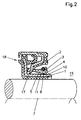
- Fig. 2 shows a second embodiment of the invention Sealing arrangement and differs from the first embodiment from Fig. 1 insofar as the machine element 1 to be sealed by the Race 17 of a cassette seal 18 is formed, the one rotated Surface 10 has.
- the surface 10 is one with a feed of 0.03 to 0.3 mm Cutting speed from 80 to 400 m / min. and a depth of cut of 0.04 tightened up to 0.4 mm.
- a turned surface 10 as a tread for radial shaft seals 2 is particularly easy and inexpensive to manufacture.
- the twist caused by that The method according to the invention arises on the surface 10 is metrological exactly recordable and in its effects on the tightness behavior of the Radial shaft sealing rings can be quantified because a twist with a incline corresponding to the feed arises.
- the advantage of the sealing arrangement according to the invention is that at Compliance with the parameters of the radial shaft seal 2 by the Shape and arrangement of its two conical surfaces 4, 5 regardless of the Direction of rotation of the machine element 1 in a medium to be sealed Promotes back direction of the space to be sealed 15, even if the Groove 11 is screwed into the surface 10 such that the medium to be sealed is axially conveyed away from the space 15 to be sealed.
Abstract
Description
Claims (7)
- Dichtungsanordnung, umfassend eine abzudichtende Oberfläche eines rotationssymmetrischen Maschinenelements und einen Radialwellendichtring, dessen aus polymerem Werkstoff bestehende Dichtlippe die Oberfläche mit einer durch zwei einander durchschneidende Kegelflächen gebildeteten Dichtkante berührt, wobei die dem abzudichtenden Raum zugewandte erste Kegelfläche mit der Rotationsachse einen steileren Kegelwinkel einschschließt als die davon abgewandte Kegelfläche, dadurch gekennzeichnet, daß in die Oberfläche (10) eine wendelförmig verlaufende Nut (11) mit gerundetem Nutgrund (12) eingedreht ist und daß der Nutgrund (12) einen Rundungsradius von 0,4 bis 1,6 mm aufweist und die Tiefe (13) der Nut (11) weniger als 15 µm beträgt.
- Dichtungsanordnung nach Anspruch 1, dadurch gekennzeichnet, daß die Tiefe (13) höchstens 10 µm beträgt.
- Dichtungsanordnung nach einem der Ansprüche 1 bis 2, dadurch gekennzeichnet, daß die einander benachbarten Wendel (14.1, 14.2, ...) der Nut (11) einen Mittelpunktsabstand von 0,03 bis 0,3 mm haben.
- Dichtungsanordnung nach einem der Ansprüche 1 bis 3, dadurch gekennzeichnet, daß die Breite der Dichtkante (6) 1,5 bis 4mal größer ist als die Steigung der Nut (11).
- Dichtungsanordnung nach einem der Ansprüche 1 bis 4, dadurch gekennzeichnet, daß das Maschinenelement (1) durch eine Welle gebildet ist.
- Dichtungsanordnung nach einem der Ansprüche 1 bis 4, dadurch gekennzeichnet, daß das Maschinenelement (1) durch einen Laufring (17) einer Kassettendichtung (18) gebildet ist.
- Verfahren zur Herstellung einer abzudichtenden Oberfläche einer Dichtungsanordnung nach einem der Ansprüche 1 bis 6, dadurch gekennzeichnet, daß die Oberfläche (10) mit einem Vorschub von 0,03 bis 0,3 mm, einer Schnittgeschwindigkeit von 80 bis 400 m/min. und einer Schnittiefe von 0,04 bis 0,4 mm überdreht wird.
Applications Claiming Priority (2)
| Application Number | Priority Date | Filing Date | Title |
|---|---|---|---|
| DE19721692A DE19721692C2 (de) | 1997-05-23 | 1997-05-23 | Dichtungsanordnung |
| DE19721692 | 1997-05-23 |
Publications (3)
| Publication Number | Publication Date |
|---|---|
| EP0879977A2 true EP0879977A2 (de) | 1998-11-25 |
| EP0879977A3 EP0879977A3 (de) | 1999-12-08 |
| EP0879977B1 EP0879977B1 (de) | 2003-05-14 |
Family
ID=7830333
Family Applications (1)
| Application Number | Title | Priority Date | Filing Date |
|---|---|---|---|
| EP98103078A Expired - Lifetime EP0879977B1 (de) | 1997-05-23 | 1998-02-21 | Dichtungsanordnung |
Country Status (8)
| Country | Link |
|---|---|
| US (2) | US6170834B1 (de) |
| EP (1) | EP0879977B1 (de) |
| JP (1) | JPH10331985A (de) |
| KR (1) | KR100293083B1 (de) |
| CN (1) | CN1200446A (de) |
| BR (1) | BR9801675A (de) |
| CA (1) | CA2235448C (de) |
| DE (2) | DE19721692C2 (de) |
Cited By (9)
| Publication number | Priority date | Publication date | Assignee | Title |
|---|---|---|---|---|
| EP1213517A2 (de) | 2000-12-05 | 2002-06-12 | Emu Unterwasserpumpen Gmbh | Gleitringdichtung für Strömungsmaschinen |
| EP1201975A3 (de) * | 2000-10-25 | 2003-08-20 | Teijin Seiki Co., Ltd. | Wellendichtungsvorrichtung |
| DE10103575B4 (de) * | 2000-12-05 | 2006-05-11 | Emu Unterwasserpumpen Gmbh | Strömungsarbeitsmaschine, z.B. Pumpe oder Rührwerk |
| US8376369B2 (en) | 2006-02-10 | 2013-02-19 | Freudenberg-Nok General Partnership | Seal with spiral grooves and contamination entrapment dams |
| US8454025B2 (en) | 2010-02-24 | 2013-06-04 | Freudenberg-Nok General Partnership | Seal with spiral grooves and mid-lip band |
| WO2013186301A3 (de) * | 2012-06-15 | 2014-02-06 | Siemens Aktiengesellschaft | Ölstauring |
| CN103815779A (zh) * | 2014-03-06 | 2014-05-28 | 金华职业技术学院 | 一种高压锅的锅体及密封圈 |
| US8919782B2 (en) | 2012-10-19 | 2014-12-30 | Freudenberg-Nok General Partnership | Dynamic lay down lip seal with bidirectional pumping feature |
| CN111575030A (zh) * | 2020-05-27 | 2020-08-25 | 焦彪彪 | 一种具有可承重密封结构的生物质热解卧式转炉 |
Families Citing this family (31)
| Publication number | Priority date | Publication date | Assignee | Title |
|---|---|---|---|---|
| DE19721692C2 (de) * | 1997-05-23 | 2000-02-24 | Freudenberg Carl Fa | Dichtungsanordnung |
| US6736404B1 (en) * | 1999-11-04 | 2004-05-18 | Dana Corporation | Shaft for use with annular seal assembly and method of manufacturing same |
| US6354598B1 (en) * | 2000-02-15 | 2002-03-12 | Skf Usa Inc. | Oil seal including wear sleeve with hydrodynamic pattern |
| JP2001066757A (ja) | 2000-08-07 | 2001-03-16 | Seiko Epson Corp | 露光方法 |
| US20030102632A1 (en) * | 2001-11-30 | 2003-06-05 | Oprea Duta | Oil seal journal texturing and method thereof |
| DE602004009152T2 (de) * | 2004-04-13 | 2008-07-03 | Corcos Industriale Di Freudenberg & Cosso S.R.L., S.A.S. | Wellendichtung |
| US7931278B2 (en) * | 2005-09-22 | 2011-04-26 | Corcos Industriale S.A.S. di Externa Italia S.R.L | Seal assembly for a rotary member |
| US8925927B2 (en) | 2006-02-10 | 2015-01-06 | Freudenberg-Nok General Partnership | Seal with controllable pump rate |
| US7775528B2 (en) | 2006-02-13 | 2010-08-17 | Freudenberg-Nok General Partnership | Bi-directional pattern for dynamic seals |
| US7494130B2 (en) | 2006-02-13 | 2009-02-24 | Freudenberg-Nok General Partnership | Bi-directional pattern for dynamic seals |
| DE102006033560B4 (de) * | 2006-07-20 | 2015-10-29 | Bayerische Motoren Werke Aktiengesellschaft | Gleitlageranordnung |
| US7891670B2 (en) | 2008-02-01 | 2011-02-22 | Freudenberg-Nok General Partnership | Multi-directional shaft seal |
| DE102010012844B4 (de) * | 2010-03-25 | 2014-03-13 | Carl Freudenberg Kg | Dichtung mit Laufhülse mit Schmiertaschen |
| EP2754928B1 (de) | 2011-09-06 | 2018-12-12 | Eagle Industry Co., Ltd. | Schaftdichtungsvorrichtung |
| CN103906953B (zh) | 2012-02-15 | 2017-04-05 | 伊格尔工业股份有限公司 | 轴封装置 |
| CN103857947B (zh) * | 2012-02-15 | 2016-03-09 | 伊格尔工业股份有限公司 | 轴封装置 |
| AU2014223641B2 (en) * | 2013-02-27 | 2016-05-05 | Federal-Mogul Corporation | Main seal for a heavy-duty vehicle wheel-end assembly |
| US20150014937A1 (en) * | 2013-03-07 | 2015-01-15 | Rolls-Royce Corporation | Seal assembly and shaft therefor |
| CN105673551B (zh) * | 2014-11-19 | 2018-03-06 | 中广核工程有限公司 | 核电厂核反应堆冷却剂泵及其静压轴封组件 |
| US10344868B2 (en) * | 2016-12-14 | 2019-07-09 | Aktiebolaget Skf | Seal assembly with detachable spacer members |
| DE102017002521B4 (de) * | 2017-03-16 | 2020-08-27 | Carl Freudenberg Kg | Dichtungsanordnung, Dichtring und Laufring einer solchen und Verfahren zur Herstellung einer solchen Dichtungsanordnung |
| EP3633245B1 (de) * | 2017-06-02 | 2022-04-20 | Nok Corporation | Dichtungsvorrichtung |
| DE102017006528A1 (de) * | 2017-07-11 | 2019-01-17 | Carl Freudenberg Kg | Dichtring |
| DE102017130039A1 (de) * | 2017-12-14 | 2019-06-19 | Elringklinger Ag | Radialwellen-Dichtungsvorrichtung und Herstellungsverfahren |
| RU180831U1 (ru) * | 2018-01-15 | 2018-06-26 | Общество с ограниченной ответственностью "БДТ АГРО" | Кассетное уплотнение |
| RU2687197C1 (ru) * | 2018-04-02 | 2019-05-07 | Акционерное общество "Военно-промышленная корпорация "Научно-производственное объединение машиностроения" | Способ обеспечения герметичности турбонасосного агрегата |
| DE102018213228A1 (de) * | 2018-08-07 | 2020-02-13 | Thyssenkrupp Ag | Wälzlager, insbesondere Wälzlager für Windkraftanlagen, mit druckunterstützter Abdichtung |
| EP3875808A4 (de) * | 2018-10-31 | 2022-08-03 | Nok Corporation | Verfahren zur oberflächenbehandlung eines scheibenelements einer abdichtungsvorrichtung und abdichtungsvorrichtung |
| CN115335619A (zh) | 2020-04-10 | 2022-11-11 | 谐波传动系统有限公司 | 润滑剂密封结构、波动齿轮装置以及致动器 |
| CN111895094B (zh) * | 2020-06-22 | 2022-09-13 | 东风柳州汽车有限公司 | 一种用于汽车发动机的封油结构 |
| DE102020209677A1 (de) * | 2020-07-31 | 2022-02-03 | Aktiebolaget Skf | Lageranordnung |
Citations (1)
| Publication number | Priority date | Publication date | Assignee | Title |
|---|---|---|---|---|
| DE15433C (de) | J. FOERSTER in Königsberg (Preufsen) | Neuerungen an der unter P. R. Nr. 12353 patentirten Druckentlastung von Retorten |
Family Cites Families (10)
| Publication number | Priority date | Publication date | Assignee | Title |
|---|---|---|---|---|
| US2301100A (en) * | 1940-06-24 | 1942-11-03 | H & H Machine And Motor Parts | Oil grooving machine |
| US3259393A (en) * | 1964-09-02 | 1966-07-05 | Gen Motors Corp | Lip seal for rotary shaft with patterned grooves |
| US4138927A (en) * | 1977-04-01 | 1979-02-13 | Hamil Ira B | Internal grooving machine |
| DE3418738C2 (de) * | 1984-05-19 | 1986-05-15 | Fa. Carl Freudenberg, 6940 Weinheim | Wellendichtung |
| US4573690A (en) * | 1984-12-13 | 1986-03-04 | General Motors Corporation | Sealing surface and method |
| DE3810741C1 (de) * | 1988-03-30 | 1989-11-09 | Fa. Carl Freudenberg, 6940 Weinheim, De | |
| AU2521692A (en) * | 1991-09-30 | 1993-04-01 | Skf Usa Inc. | Pumping feature on wear sleeve for unitized seal |
| RU2044606C1 (ru) * | 1993-04-30 | 1995-09-27 | Николай Николаевич Зубков | Способ получения поверхностей с чередующимися выступами и впадинами (варианты) и инструмент для его осуществления |
| US5910199A (en) * | 1997-02-26 | 1999-06-08 | Vickers, Incorporated | Method and apparatus for fast threading pullout in a numerically controlled threading application |
| DE19721692C2 (de) * | 1997-05-23 | 2000-02-24 | Freudenberg Carl Fa | Dichtungsanordnung |
-
1997
- 1997-05-23 DE DE19721692A patent/DE19721692C2/de not_active Revoked
-
1998
- 1998-02-21 EP EP98103078A patent/EP0879977B1/de not_active Expired - Lifetime
- 1998-02-21 DE DE59808322T patent/DE59808322D1/de not_active Expired - Fee Related
- 1998-05-21 US US09/083,076 patent/US6170834B1/en not_active Expired - Fee Related
- 1998-05-21 CN CN98108339A patent/CN1200446A/zh active Pending
- 1998-05-21 BR BR9801675A patent/BR9801675A/pt active Search and Examination
- 1998-05-22 CA CA002235448A patent/CA2235448C/en not_active Expired - Fee Related
- 1998-05-23 KR KR1019980020158A patent/KR100293083B1/ko not_active IP Right Cessation
- 1998-05-25 JP JP10143023A patent/JPH10331985A/ja active Pending
-
2000
- 2000-09-18 US US09/663,986 patent/US6357325B1/en not_active Expired - Fee Related
Patent Citations (1)
| Publication number | Priority date | Publication date | Assignee | Title |
|---|---|---|---|---|
| DE15433C (de) | J. FOERSTER in Königsberg (Preufsen) | Neuerungen an der unter P. R. Nr. 12353 patentirten Druckentlastung von Retorten |
Cited By (13)
| Publication number | Priority date | Publication date | Assignee | Title |
|---|---|---|---|---|
| US7090222B2 (en) | 2000-10-25 | 2006-08-15 | Teijin Seiki Co., Ltd. | Shaft sealing assembly for vacuum processing apparatus |
| EP1201975A3 (de) * | 2000-10-25 | 2003-08-20 | Teijin Seiki Co., Ltd. | Wellendichtungsvorrichtung |
| EP1640645A1 (de) * | 2000-10-25 | 2006-03-29 | Teijin Seiki Co., Ltd. | Wellendichtungsvorrichtung |
| US7055825B2 (en) | 2000-10-25 | 2006-06-06 | Teijin Seiki Co., Ltd. | Shaft sealing apparatus |
| US6612805B2 (en) | 2000-12-05 | 2003-09-02 | Emu Unterwasserpumpen Gmbh | Hydrodynamic machine |
| DE10103575B4 (de) * | 2000-12-05 | 2006-05-11 | Emu Unterwasserpumpen Gmbh | Strömungsarbeitsmaschine, z.B. Pumpe oder Rührwerk |
| EP1213517A2 (de) | 2000-12-05 | 2002-06-12 | Emu Unterwasserpumpen Gmbh | Gleitringdichtung für Strömungsmaschinen |
| US8376369B2 (en) | 2006-02-10 | 2013-02-19 | Freudenberg-Nok General Partnership | Seal with spiral grooves and contamination entrapment dams |
| US8454025B2 (en) | 2010-02-24 | 2013-06-04 | Freudenberg-Nok General Partnership | Seal with spiral grooves and mid-lip band |
| WO2013186301A3 (de) * | 2012-06-15 | 2014-02-06 | Siemens Aktiengesellschaft | Ölstauring |
| US8919782B2 (en) | 2012-10-19 | 2014-12-30 | Freudenberg-Nok General Partnership | Dynamic lay down lip seal with bidirectional pumping feature |
| CN103815779A (zh) * | 2014-03-06 | 2014-05-28 | 金华职业技术学院 | 一种高压锅的锅体及密封圈 |
| CN111575030A (zh) * | 2020-05-27 | 2020-08-25 | 焦彪彪 | 一种具有可承重密封结构的生物质热解卧式转炉 |
Also Published As
| Publication number | Publication date |
|---|---|
| KR100293083B1 (ko) | 2001-09-28 |
| DE19721692C2 (de) | 2000-02-24 |
| DE59808322D1 (de) | 2003-06-18 |
| CA2235448A1 (en) | 1998-11-23 |
| CN1200446A (zh) | 1998-12-02 |
| JPH10331985A (ja) | 1998-12-15 |
| US6170834B1 (en) | 2001-01-09 |
| US6357325B1 (en) | 2002-03-19 |
| CA2235448C (en) | 2003-08-26 |
| EP0879977A3 (de) | 1999-12-08 |
| EP0879977B1 (de) | 2003-05-14 |
| BR9801675A (pt) | 1999-04-06 |
| DE19721692A1 (de) | 1998-11-26 |
| KR19980087547A (ko) | 1998-12-05 |
Similar Documents
| Publication | Publication Date | Title |
|---|---|---|
| EP0879977B1 (de) | Dichtungsanordnung | |
| DE19956971B4 (de) | Kegelrollenlager und Getriebewellen-Lagervorrichtung | |
| AT514570A4 (de) | Zahnrad | |
| DE60024344T4 (de) | Rollenlager und ein Herstellungsverfahren desselben | |
| DD154633B1 (de) | Fluidgleitlager | |
| DE3839106A1 (de) | Gleitringdichtung | |
| DE3722303A1 (de) | Gleitringdichtung zur abdichtung eines gasfoermigen mediums | |
| EP3800375A1 (de) | Zahnkranzträgerteil für ein zwei- oder mehrkomponenten-zahnrad sowie zwei- oder mehrkomponenten-zahnrad mit einem derartigen zahnkranzträgerteil | |
| DE112015004978T5 (de) | Kegelrollenlager | |
| EP0991871B1 (de) | Einrichtung mit einer welle und mit zumindest einer auf dieser welle angebrachten nabe sowie ein verfahren zur herstellung dieser einrichtung | |
| DE60211613T2 (de) | Rollenlagerkäfig | |
| EP1440254B1 (de) | Getriebe mit schmiernuten | |
| EP2431565A1 (de) | Hartmetallkopf für ein Werkzeug zum Bearbeiten von Feststoffmaterial | |
| DE2756929C2 (de) | Dichtungsring | |
| DE19963897B4 (de) | Verfahren zur drallfreien spanenden Bearbeitung von rotationssymmetrischen Flächen | |
| DE2644992C2 (de) | ||
| EP0960963A2 (de) | Lagerung für einen Offenend-Spinnrotor mittels Stützscheiben | |
| EP1812721A1 (de) | Kegelrollenlager | |
| DE3531044A1 (de) | Werkzeug und verfahren zum profilieren und abrichten einer schleifscheibe fuer das aussengewindeschleifen | |
| DE10107485A1 (de) | Sintergleitlager mit mehreren Laufzonen | |
| DE112015004915T5 (de) | Käfig für Kegelrollenlager und Kegelrollenlager | |
| DE2902820A1 (de) | Lagerung fuer einen offenend-spinnrotor | |
| DE102020110255A1 (de) | Hydrodynamische druckscheiben mit pumpmerkmalen für anwendungen mit spärlicher schmierung | |
| DE102006057576A1 (de) | Rotationsschneidlinie | |
| DE202019105432U1 (de) | Zahnkranzträgerteil für ein Zwei- oder Mehrkomponenten-Zahnrad sowie Zwei- oder Mehrkomponenten-Zahnrad mit einem derartigen Zahnkranzträgerteil |
Legal Events
| Date | Code | Title | Description |
|---|---|---|---|
| PUAI | Public reference made under article 153(3) epc to a published international application that has entered the european phase |
Free format text: ORIGINAL CODE: 0009012 |
|
| AK | Designated contracting states |
Kind code of ref document: A2 Designated state(s): DE ES FR GB IT SE |
|
| AX | Request for extension of the european patent |
Free format text: AL;LT;LV;MK;RO;SI |
|
| PUAL | Search report despatched |
Free format text: ORIGINAL CODE: 0009013 |
|
| AK | Designated contracting states |
Kind code of ref document: A3 Designated state(s): AT BE CH DE DK ES FI FR GB GR IE IT LI LU MC NL PT SE |
|
| AX | Request for extension of the european patent |
Free format text: AL;LT;LV;MK;RO;SI |
|
| 17P | Request for examination filed |
Effective date: 19991112 |
|
| AKX | Designation fees paid |
Free format text: DE ES FR GB IT SE |
|
| RAP1 | Party data changed (applicant data changed or rights of an application transferred) |
Owner name: CARL FREUDENBERG KG |
|
| GRAH | Despatch of communication of intention to grant a patent |
Free format text: ORIGINAL CODE: EPIDOS IGRA |
|
| GRAH | Despatch of communication of intention to grant a patent |
Free format text: ORIGINAL CODE: EPIDOS IGRA |
|
| GRAA | (expected) grant |
Free format text: ORIGINAL CODE: 0009210 |
|
| AK | Designated contracting states |
Designated state(s): DE ES FR GB IT SE |
|
| REG | Reference to a national code |
Ref country code: GB Ref legal event code: FG4D Free format text: NOT ENGLISH |
|
| REF | Corresponds to: |
Ref document number: 59808322 Country of ref document: DE Date of ref document: 20030618 Kind code of ref document: P |
|
| GBT | Gb: translation of ep patent filed (gb section 77(6)(a)/1977) | ||
| PG25 | Lapsed in a contracting state [announced via postgrant information from national office to epo] |
Ref country code: SE Free format text: LAPSE BECAUSE OF FAILURE TO SUBMIT A TRANSLATION OF THE DESCRIPTION OR TO PAY THE FEE WITHIN THE PRESCRIBED TIME-LIMIT Effective date: 20030814 |
|
| PG25 | Lapsed in a contracting state [announced via postgrant information from national office to epo] |
Ref country code: ES Free format text: LAPSE BECAUSE OF FAILURE TO SUBMIT A TRANSLATION OF THE DESCRIPTION OR TO PAY THE FEE WITHIN THE PRESCRIBED TIME-LIMIT Effective date: 20030825 |
|
| ET | Fr: translation filed | ||
| PG25 | Lapsed in a contracting state [announced via postgrant information from national office to epo] |
Ref country code: GB Free format text: LAPSE BECAUSE OF NON-PAYMENT OF DUE FEES Effective date: 20040221 |
|
| PLBE | No opposition filed within time limit |
Free format text: ORIGINAL CODE: 0009261 |
|
| STAA | Information on the status of an ep patent application or granted ep patent |
Free format text: STATUS: NO OPPOSITION FILED WITHIN TIME LIMIT |
|
| 26N | No opposition filed |
Effective date: 20040217 |
|
| PG25 | Lapsed in a contracting state [announced via postgrant information from national office to epo] |
Ref country code: DE Free format text: LAPSE BECAUSE OF NON-PAYMENT OF DUE FEES Effective date: 20040901 |
|
| GBPC | Gb: european patent ceased through non-payment of renewal fee |
Effective date: 20040221 |
|
| PG25 | Lapsed in a contracting state [announced via postgrant information from national office to epo] |
Ref country code: FR Free format text: LAPSE BECAUSE OF NON-PAYMENT OF DUE FEES Effective date: 20041029 |
|
| REG | Reference to a national code |
Ref country code: FR Ref legal event code: ST |
|
| PG25 | Lapsed in a contracting state [announced via postgrant information from national office to epo] |
Ref country code: IT Free format text: LAPSE BECAUSE OF NON-PAYMENT OF DUE FEES Effective date: 20050221 |