EP1213401B1 - Rundwandeinrichtung - Google Patents
Rundwandeinrichtung Download PDFInfo
- Publication number
- EP1213401B1 EP1213401B1 EP01128871A EP01128871A EP1213401B1 EP 1213401 B1 EP1213401 B1 EP 1213401B1 EP 01128871 A EP01128871 A EP 01128871A EP 01128871 A EP01128871 A EP 01128871A EP 1213401 B1 EP1213401 B1 EP 1213401B1
- Authority
- EP
- European Patent Office
- Prior art keywords
- curved wall
- foam core
- mortar
- reinforced
- mortar coating
- Prior art date
- Legal status (The legal status is an assumption and is not a legal conclusion. Google has not performed a legal analysis and makes no representation as to the accuracy of the status listed.)
- Expired - Lifetime
Links
Images

Classifications
-
- B—PERFORMING OPERATIONS; TRANSPORTING
- B28—WORKING CEMENT, CLAY, OR STONE
- B28B—SHAPING CLAY OR OTHER CERAMIC COMPOSITIONS; SHAPING SLAG; SHAPING MIXTURES CONTAINING CEMENTITIOUS MATERIAL, e.g. PLASTER
- B28B11/00—Apparatus or processes for treating or working the shaped or preshaped articles
- B28B11/003—Apparatus or processes for treating or working the shaped or preshaped articles the shaping of preshaped articles, e.g. by bending
-
- A—HUMAN NECESSITIES
- A47—FURNITURE; DOMESTIC ARTICLES OR APPLIANCES; COFFEE MILLS; SPICE MILLS; SUCTION CLEANERS IN GENERAL
- A47K—SANITARY EQUIPMENT; ACCESSORIES THEREFOR, e.g. TOILET ACCESSORIES
- A47K3/00—Baths; Showers; Appurtenances therefor
- A47K3/28—Showers or bathing douches
- A47K3/30—Screens or collapsible cabinets for showers or baths
-
- B—PERFORMING OPERATIONS; TRANSPORTING
- B32—LAYERED PRODUCTS
- B32B—LAYERED PRODUCTS, i.e. PRODUCTS BUILT-UP OF STRATA OF FLAT OR NON-FLAT, e.g. CELLULAR OR HONEYCOMB, FORM
- B32B13/00—Layered products comprising a a layer of water-setting substance, e.g. concrete, plaster, asbestos cement, or like builders' material
- B32B13/04—Layered products comprising a a layer of water-setting substance, e.g. concrete, plaster, asbestos cement, or like builders' material comprising such water setting substance as the main or only constituent of a layer, which is next to another layer of the same or of a different material
- B32B13/12—Layered products comprising a a layer of water-setting substance, e.g. concrete, plaster, asbestos cement, or like builders' material comprising such water setting substance as the main or only constituent of a layer, which is next to another layer of the same or of a different material of synthetic resin
-
- E—FIXED CONSTRUCTIONS
- E04—BUILDING
- E04C—STRUCTURAL ELEMENTS; BUILDING MATERIALS
- E04C2/00—Building elements of relatively thin form for the construction of parts of buildings, e.g. sheet materials, slabs, or panels
- E04C2/02—Building elements of relatively thin form for the construction of parts of buildings, e.g. sheet materials, slabs, or panels characterised by specified materials
- E04C2/26—Building elements of relatively thin form for the construction of parts of buildings, e.g. sheet materials, slabs, or panels characterised by specified materials composed of materials covered by two or more of groups E04C2/04, E04C2/08, E04C2/10 or of materials covered by one of these groups with a material not specified in one of the groups
- E04C2/284—Building elements of relatively thin form for the construction of parts of buildings, e.g. sheet materials, slabs, or panels characterised by specified materials composed of materials covered by two or more of groups E04C2/04, E04C2/08, E04C2/10 or of materials covered by one of these groups with a material not specified in one of the groups at least one of the materials being insulating
- E04C2/288—Building elements of relatively thin form for the construction of parts of buildings, e.g. sheet materials, slabs, or panels characterised by specified materials composed of materials covered by two or more of groups E04C2/04, E04C2/08, E04C2/10 or of materials covered by one of these groups with a material not specified in one of the groups at least one of the materials being insulating composed of insulating material and concrete, stone or stone-like material
-
- E—FIXED CONSTRUCTIONS
- E04—BUILDING
- E04C—STRUCTURAL ELEMENTS; BUILDING MATERIALS
- E04C2/00—Building elements of relatively thin form for the construction of parts of buildings, e.g. sheet materials, slabs, or panels
- E04C2/02—Building elements of relatively thin form for the construction of parts of buildings, e.g. sheet materials, slabs, or panels characterised by specified materials
- E04C2/26—Building elements of relatively thin form for the construction of parts of buildings, e.g. sheet materials, slabs, or panels characterised by specified materials composed of materials covered by two or more of groups E04C2/04, E04C2/08, E04C2/10 or of materials covered by one of these groups with a material not specified in one of the groups
- E04C2/284—Building elements of relatively thin form for the construction of parts of buildings, e.g. sheet materials, slabs, or panels characterised by specified materials composed of materials covered by two or more of groups E04C2/04, E04C2/08, E04C2/10 or of materials covered by one of these groups with a material not specified in one of the groups at least one of the materials being insulating
- E04C2/296—Building elements of relatively thin form for the construction of parts of buildings, e.g. sheet materials, slabs, or panels characterised by specified materials composed of materials covered by two or more of groups E04C2/04, E04C2/08, E04C2/10 or of materials covered by one of these groups with a material not specified in one of the groups at least one of the materials being insulating composed of insulating material and non-metallic or unspecified sheet-material
-
- E—FIXED CONSTRUCTIONS
- E04—BUILDING
- E04C—STRUCTURAL ELEMENTS; BUILDING MATERIALS
- E04C2/00—Building elements of relatively thin form for the construction of parts of buildings, e.g. sheet materials, slabs, or panels
- E04C2/30—Building elements of relatively thin form for the construction of parts of buildings, e.g. sheet materials, slabs, or panels characterised by the shape or structure
- E04C2/32—Building elements of relatively thin form for the construction of parts of buildings, e.g. sheet materials, slabs, or panels characterised by the shape or structure formed of corrugated or otherwise indented sheet-like material; composed of such layers with or without layers of flat sheet-like material
- E04C2/328—Building elements of relatively thin form for the construction of parts of buildings, e.g. sheet materials, slabs, or panels characterised by the shape or structure formed of corrugated or otherwise indented sheet-like material; composed of such layers with or without layers of flat sheet-like material slightly bowed or folded panels not otherwise provided for
-
- B—PERFORMING OPERATIONS; TRANSPORTING
- B28—WORKING CEMENT, CLAY, OR STONE
- B28B—SHAPING CLAY OR OTHER CERAMIC COMPOSITIONS; SHAPING SLAG; SHAPING MIXTURES CONTAINING CEMENTITIOUS MATERIAL, e.g. PLASTER
- B28B19/00—Machines or methods for applying the material to surfaces to form a permanent layer thereon
- B28B19/003—Machines or methods for applying the material to surfaces to form a permanent layer thereon to insulating material
-
- B—PERFORMING OPERATIONS; TRANSPORTING
- B28—WORKING CEMENT, CLAY, OR STONE
- B28B—SHAPING CLAY OR OTHER CERAMIC COMPOSITIONS; SHAPING SLAG; SHAPING MIXTURES CONTAINING CEMENTITIOUS MATERIAL, e.g. PLASTER
- B28B21/00—Methods or machines specially adapted for the production of tubular articles
- B28B21/70—Methods or machines specially adapted for the production of tubular articles by building-up from preformed elements
Definitions
- the invention relates a method for producing curved wall arc segments according to the preamble of claim 1.
- a circular wall device is known from DE-C-4 100 737. It consists of 3 - 8 arched elements, which pass through on the sides each matching tongue and groove elements to a cylindrical Tube are joined together. This tube comes with a bottom element with a circular groove and running towards the middle Slope and a cover element to a round shower together. In the middle of the floor element is a Ground opening provided.
- the arch elements and the floor and Deckelelemnet are made of a plastic foam produced by foaming or cutting For surface reinforcement is applied to the floor element and the inside and outside the tube a layer of glass fiber reinforced concrete applied.
- the disadvantage is that the plastic foam parts uncoated transported to the site and assembled there become.
- the soft plastic foam is indeed light but fragile and not resilient, so that the items can become unusable.
- Another Disadvantage is that after cutting out an access opening only with the inner coating is started.
- the narrow tube complicates the coating work. Must with the soft tube material in the area of the access opening a cabin door can be connected, find the Connecting elements no stop
- a wall device which is constructed from building boards, is from the German company brochure: wediwelt, issue 09, June 2000, P. 5 shown.
- Level building boards are made of are from DE-C-4,234,269. They consist of a foam core, coated on both sides with a reinforced mortar layer is.
- the disadvantage is that the wedge-shaped cuts a the two reinforced mortar layers and the foam core get hurt. This not only strengthens but also impairs the liquid tightness of the plate.
- the plates are only glued together to the plate width, the transverse stability and the torsional rigidity to increase.
- the Bend can be made both concave and convex.
- the at least partially elastic rigid plastic foam takes the strain and the compression on.
- the reinforced mortar layer follows the concave or convex Rounding without breaking.
- the bending radius is at a one-sided coated building board of 600 mm width and a length of 1250 or 2500 mm about 250 mm (0.25 m). Also underlying bending radii are possible if at Plastic mortar, the plastic content and thus the bending possibility is increased.
- the bending radius is as through Experiments determined, preferably 500 mm
- the thickness of the plate foam core can vary between 5 and 50 mm.
- the foam core needs the Bogenteilwand not under high production costs from a Block cut out and then by hand with two be coated opposite mortar layers. Rather, the already running plant for producing the Building boards are used, so that the necessary investment costs for the production facilities.
- the wall segments can each other on their narrow sides be connected to the circular wall device.
- first and second reinforced mortar layers at least partially overhanging the foam core as a mortar layer protrusion surface element. It may also be facilitated by disposing at least the first sheet of sheet metal of one of the sheet segments spaced at a narrow side on the first sheet foam core and adhering one of the reinforced sheet layer overhang sheets to the core strip.
- Connecting foam core can be used.
- the protruding layer of mortar layer supernatant can glued on and so the connection the individual wall segments to a bow wall device increase.
- the abutting mortar layer protrusion surface elements can be pasted over with a joint sealing tape become. As a result, both the strength and the Ensures liquid tightness.
- the reinforced mortar layers can also, as already executed with the same advantages over the foam boards survive.
- arched foam cores with reinforced arch mortar layers are coated as well as the smooth and flat building boards. This makes it possible to use them as partitions to be used for applications of any kind.
- An arch partition may consist of a first with a first Arch mortar layer coated sheet metal foam core and a second with a second sheet of sheet mortar coated sheet-metal foam core. Both Cores can attach to their uncoated foam sheet surfaces be connected to each other. This is a simple and cost-effective production of the arch part walls possible.
- the first and second sheet mortar layers may be at least one of the narrow sides at least partially with a survive reinforced mortar layer supernatant surface element. These mortar layer protrusion surface elements simplify a strength and fluid-proof connection the individual wall arch segments.
- connection can be made by a compound foam core be relieved, between the two narrow sides and the insides of the mortar layer protrusion surface elements can be arranged. Due to the intimate connection of the connecting foam core with the essential parts of Wall arch segments is a one-piece design of a circular wall device guaranteed any length.
- the first arch mortar layer of one of the wall arch segments can connect to a narrow side) on the first Arch plate foam core arranged at a distance be.
- One of the reinforced mortar layer protruding surface elements can then be glued on the core strip
- the reinforced sheet mortar layers and the reinforced mortar layer protrusion surface elements can be made of a fiberglass fabric consist, at least partially, in a curable Mortar layer is embedded.
- the embedding of the Fiberglass fabric in the mortar layer ensures the wall-like properties of the inherently soft foam core.
- the glass fiber fabric may have a mesh size, the between 0.25 to 0.6 x 0.25 to 0.6 cm and between 0.4 to 0.7 x 0.9 to 1.1 cm can vary.
- a mesh size ensures optimal use of mortar.
- the selected mesh size ensures optimal use of mortar.
- Will the Increased mesh size must to achieve the same strength properties the thread thickness are increased.
- the Enlargement of the thread thickness is but with a substantial Increase the amount of mortar to form the armored Mortar layer connected.
- the second mesh size which is has proven in practice tests is one of 0.5 x 0.5 mm. The Reduction of the mesh size leads to a very effective Increase in strength.
- the mortar layer For the production of the mortar layer is a plastic-coated Cement mortar used.
- the cement or plastic parts can increase the elasticity and the waterproofness of the mortar layer are affected.
- FIGs 5, 6 and 7 the individual elements of a circular wall device are shown. It can be used for partitions or entrance areas in prestigious buildings.
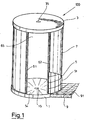
- the circular wall device is here as a shower surround device 7 part of a round shower 100, as shown in Figures 1 and 2.
- the shower surround device 7 is composed of several wall-arch segments 71.1,... 71.n.
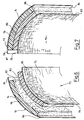
- FIG. 6 shows a wall segment 71.1,... Before completion. It consists of two arch part walls 72, 73 made of a rigid plastic foam, which are coated on one side with a reinforced arch mortar layer 74, 75.
- Armored sheet mortar layer 74 projects to one side as a mortar layer protrusion surface element 78 and on the opposite side as a mortar layer protrusion surface element 84.
- the reinforced sheet mortar layer 75 projects on one side as a mortar layer protrusion surface element 79 and on the other side as a mortar layer protrusion surface element 85.
- At least one curved mortar layer of one of the wall-arch segments 71.1,..., 71.n to be arranged at a narrow side 87, 88 on a sheet-metal foam core and one of the reinforced mortar-layer protrusion surface elements to be glued onto the free core strip.
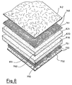
- straight and level Plate foam cores 760, 770 coated on one side with a reinforced mortar layer 740, 750 are, with a plate width of 600 mm and a Plate length of 1250 or 2500 mm to the arch part walls 72, 73 bend.
- a bending radius of about 500 mm as a manufacturing technology realized feasible.
- the plate foam core 760, 770 takes the upsets or strains.
- the occurring stresses (restoring forces) when bending the plate foam core are through voltage-reducing measures, such as short-term shock-temperature treatment, Scoring of the foam core or long term temperature treatments reduced. In general, heat applied. But it can be used cold.
- the particular advantage is that the flat plate foam cores 760, 770 according to the method according to DE 42 34 269 C1 are coated so that on the already existing Coating plant without additional investment costs can be used.
- coating will be the plate foam cores 760, 770 of FIG. 8 on a Conveyor laid. After that, it will be free of tension Roll of fiberglass fabric strip peeled off and in one on the Plate foam cores applied and distributed mortar layer 742, 752 impressed.
- the in the liquid mortar layer introduced fiberglass tissue web cut in fiberglass fabric 741, 751.
- the on the Plate foam cores 760, 770 depleted liquid Mortar layer with the embedded glass fiber fabric is in dried in a drying oven and further processing fed.
- the plate foam cores 760, 770 thus provided with the reinforced mortar layer 740, 750 are bent in a concave or convex manner relative to the two arch partial walls 72, 73. Thereafter, the two arch part walls 72, 73 are provided on their uncoated foam sheet surface element 82, 83 with an adhesive surface element 86 and glued to a wall arch segment 71.1, ..
- a costly coating of the free foam sheet surface elements 82, 83 is avoided by hand, as is known from DE 32 23 006 C2 and DE 41 00 737 C1.
- the previously described mortar layer projection surface elements 78, 79, 84, 85 are also formed.
- FIG. 5 shows how the individual wall-arch segments 71.1, ... be assembled to a circular wall device 7.
- a compound foam core 80 is attached to those at 87, 88 labeled narrow sides of the wall segments glued. Because the compound foam core 80 is relatively narrow, he does not need to provide an inner or outer rounding become. When sticking the compound foam core 80 also becomes a bond with the mortar layer protrusion surface elements 78, 79, 84, 85 made.
- the shower trays floor, the shower tray ceiling and the shower trays-round wall device 7 are through a shower panel 5 disguised.
- a shower panel 5 disguised.
- the shower panel 5 may be a bathroom floor 9 and a wall panel (not shown) be formed.
- the shower tray bottom device 1 and the shower tray ceiling device 3 the same Build up. They are shown in detail in FIG.
- Both the shower tray ground device 1 and the shower tray ceiling device 3 consist of a foam core 11, 31 made of rigid plastic foam or a other organic or inorganic substance.
- the outer configuration tailored to the foam core In the manufacture of the foam core is of a Foam block first a slice of appropriate thickness cut off. Subsequently, the outer configuration tailored to the foam core. In the illustrated in Figure 3 Cup foam core 11, 31 has this one round configuration on. When circular cutting can at the same time a circumferential annular recess 16, 36 in the Foam core to be cut with. Also in the same step or subsequently becomes a funnel recess 14, 34 cut. Of particular advantage is that the funnel recess is formed so that they the appropriate gradient to a procedure to be introduced or withdrawal recess 15, 35 guaranteed. Is the funnel recess cut, this is then with a reinforced funnel mortar layer 13, 33 coated. The TrichterausEnglishung opposite straight surface The cup foam core comes with a reinforced mortar coating 12, 32 provided.
- both shower tray ground facility as well shower cup ceiling device substantially the same design. Manufacturing technology has the great advantage that manufactured in series the same cup facilities which can then be used accordingly.
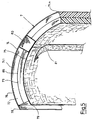
- the annular recess 16 is in the cup foam core so deeply and so broad introduced (see also Fig. 4) that the Wall 7, 46, 47 can be safely used.
- the cup foam core and also the foam core of the Wall 7, 46, 47 and the reinforced mortar layers thereon are not injured, the humidity is none Ways to get into the substructure, on the the round shower 100 is placed.
- drain recess 15 On the raw concrete of the bathroom is first a substructure applied and on this the shower tray ground facility 1 attached.
- a drain pot element inserted, which connected to a drain line is.
- the drain line terminates in a line connection element, that with the pot connection element of Abflußtopfelements connected is.
- the pot connection element In the pot connection element is in a Dichtungsingnut a seal inserted, which is a waterproof Ensured connection to the drain line.
- the wall segments 71.1, ... composed shower circular wall device 7 on the shower tray device placed so that the compound Wall arc segments 71.1, ..., as Figure 4 shows, the exact fit the Fill annular recesses 16. Because the cup foam core 11 is at least partially elastic he intimately used the shower-round wall device 7. Unroundings of the circular wall device 7 are also here with balanced. The bond between the circular wall device 7 and the armored foam core is so firmly that even now a shower would be possible.
- the shower tray ceiling device 3 can then be placed become. This gives the round shower a very effective conclusion.
- the fact that the shower trays ceiling device as well as the shower tray ground facility the circumferential Ring recess 16 contains, here is the very Ensures intimate and effective connection.
- shower panel 5 is produced.
- a shower panel come on the outside the wall device 7 wall outer tiles 51 and inside the Round shower wall interior tiles 53 are used.
- the shower tray ceiling device 3 can also use the same tiles to be tainted.
- the round shower is used, secure the one-piece shower tray ground facility 1, the one-piece shower surround device 7, the one-piece shower tray ceiling device 3 and the bond between the shower surround device 7 and the two cup devices, due to the Ring recess 16 and 36, that the round shower 100 on all sides is liquid-tight. Even the smallest amounts of moisture will be denied exit to the outside. Thereby, that the devices 1, 3 and 7 are completely coated Plastic hard foam, they lead to none massive load on the ceiling, so that the round shower 100 especially for the retrofitting of existing buildings suitable. Another advantage of the one-piece design Devices 1, 3 and 7 is that they due to the mortar layers Strength properties as cast from concrete or from stone masonry parts of the round shower 100 have. By enclosing the ends of the shower surround device 7 with the at least partially continuous trained perforated U-profiles 61, 62 are all Door types that can close the door recess 65, kept safe.
Landscapes
- Engineering & Computer Science (AREA)
- Architecture (AREA)
- Structural Engineering (AREA)
- Civil Engineering (AREA)
- Public Health (AREA)
- Health & Medical Sciences (AREA)
- Mechanical Engineering (AREA)
- General Health & Medical Sciences (AREA)
- Epidemiology (AREA)
- Ceramic Engineering (AREA)
- Chemical & Material Sciences (AREA)
- Finishing Walls (AREA)
- Building Environments (AREA)
- Forms Removed On Construction Sites Or Auxiliary Members Thereof (AREA)
- Absorbent Articles And Supports Therefor (AREA)
- Cultivation Receptacles Or Flower-Pots, Or Pots For Seedlings (AREA)
- Massaging Devices (AREA)
- Tubes (AREA)
- Percussion Or Vibration Massage (AREA)
Description
Es kann auch dadurch erleichtert werden, wenn wenigstens die erste Bogenmörtelschicht eines der Wandbogensegmente an einer Schmalseite auf dem ersten Bogenplatten-Schaumstoffkern beabstandet angeordnet wird und wenn eines der armierten Mörtelschicht- Überstandsflächenelemente auf dem Kernstreifen aufgeklebt wird.
- eine erste Schaumstoffplatte (Plattenschaumstoffkern) mit einer auf einer Flachseite aufgebrachten ersten armierten Mörtelschicht wird konkav zu einem ersten Bogenteilelement gebogen,
- eine zweite Schaumstoffplatte mit einer auf einer Flachseite aufgebrachten zweiten armierten Mörtelschicht wird konvex zu einem zweiten Bogenteilelement (Bogenteilelemnt) gebogen und
- das erste Bogenteilelement und das zweite Bogenteilelement werden mit ihren jeweils unbeschichteten Flachseiten verbunden.
- Fig. 1
- eine Runddusche mit einer Rundwandeinrichtung in einer schematischen,perspektivischen Darstellung;
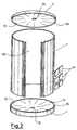
- Fig. 2
- eine Runddusche gemäß Fig. 1 in einer auseinandergezogenen Darstellung;
- Fig. 3
- eine Duschtasseneinrichtung für eine Runddusche gemäß Fig. 1 in einer perspektivischen Schnittdarstellung;
- Fig. 4
- eine in eine Duschtasseneinrichtung eingesetzte Rundwandeinrichtung in einer schematisch dargestellten Teilschnitt-Darstellung;
- Fig. 5
- eine Rundwandeinrichtung gemäß den Fig. 1, 2 und 4 in einer schematischen, perspektivischen Darstellung;
- Fig. 6
- ein Wandbogensegment für eine Rundwandeinrichtung gemäß Fig. 5 in einer teilweise auseinandergezogenen schematischen, perspektivischen Darstellung;
- Fig. 7
- ein Wandbogensegment gemäß Fig. 6 in einer zusammegesetzten schematischen, perspektivischen Darstellung und
- Fig. 8
- zwei einseitig mit einer armierten Mörtelschicht beschichtete Plattenschaumstoffkerne für eine Herstellung eines Wandbogensegments gemäß Fig. 6 und 7 in einer schematischen, auseinandergezogenen perspektivischen Darstellung.
Sie kann für Trennwände oder Eingangsbereiche in repräsentativen Gebäuden eingesetzt werden.
Die Rundwandeinrichtung ist hier als Dusch-Rundwandeinrichtung 7 Teil einer Runddusche 100, wie sie in den Figuren 1 und 2 dargestellt ist.
Es besteht aus zwei Bogenteilwänden 72, 73 aus einem Kunststoff-Hartschaum, die einseitig mit einer armierten Bogenmörtelschicht 74, 75 beschichtet sind. Die armierte Bogenmörtelschicht 74 ragt zu einer Seite als ein Mörtelschicht-Überstandsflächenelement 78 und auf der gegenüberliegenden Seite als ein Mörtelschicht-Überstandsflächenelement 84 Über. In gleicher Weise ragt die armierte Bogenmörtelschicht 75 auf der einen Seite als Mörtelschicht- Überstandsflächenelement 79 und auf der anderen Seite als ein Mörtelschicht-Überstandsflächenelement 85 über.
Es kann aber auch wenigstens eine Bogenmörtelschicht eines der Wandbogensegmente 71.1, ..., 71.n an einer Schmalseite 87, 88 auf einem Bogenplatten-Schaumstoffkern beabstandet angeordnet werden und eines der armierten Mörtelschicht-Überstandsflächenelemente auf den freien Kernstreifen aufgeklebt werden.
Beim Beschichten werden zugleich die bereits beschriebenen Mörtelschicht-Überstandsflächenelemente 78, 79, 84, 85 mit ausgebildet.
Claims (8)
- Verfahren zur Herstellung gekrümmter Wandbogensegmente (71.1, 71.n), die aus zwei verbundenen, jeweils einen Schaumstoffkern (760, 770) aufweisenden Bogenteilwänden (72, 73) bestehen, gekennzeichnet durch folgende Verfahrensschritte:a) eine erste Platte, bestehend aus einem Schaumstoffkern (760) mit auf einer Flachseite (821) aufgebrachten und mit einem Glasfasergewebe (741) armierten Mörtelschicht (740) wird konkav, d.h. mit außen auf dem Krümmungsbogen liegender Mörtelschicht, zu einer ersten Bogenteilwand (72) gebogen,b) eine zweite Platte, bestehend aus einem Schaumstoffkern (770) mit auf einer Flachseite (831) aufgebrachten und mit einem Glasfasergewebe (751) armierten Mörtelschicht (750) wird konvex, d. h. mit innen auf dem Krümmungsbogen liegender Mörtelschicht, zu einer zweiten Bogenteilwand (73) gebogen,c) die erste Bogenteilwand (72) und die zweite Bogenteilwand (73) werden mit ihren jeweils unbeschichteten Flachseiten (820,830) verbunden und bilden danach ein Wandbogensegment (71.1), das mit gleichen Wandbogensegmenten (71.n)an seinen Schmalseiten (87, 88) verbindbar ist.
- Verfahren nach Anspruch 1, dadurch gekennzeichnet, dass die beim Biegen auftretenden Spannungen und Rückstellkräfte durch Temperaturbehandlung der Bogenteilwände (72, 73) abgebaut werden.
- Verfahren nach Anspruch 1, dadurch gekennzeichnet, dass die Mörtelschicht (740, 750) auf dem ersten und dem zweiten Schaumstoffkern (760, 770) mit einem armierten Mörtelschicht-Überstandselement (78, 79, 84, 85) aufgebracht wird.
- Verfahren nach Anspruch 3, dadurch gekennzeichnet, dass bei dem Verbinden der gebogenen Wandbogensegmente untereinander zwischen den sich gegenüberliegenden Schmalseiten (87, 88) zweier Wandbogensegmente (71.1, 71,n) ein Verbindungsschaumstoffkern (80) eingeklebt wird, auf den die armierten Mörtelschicht-Überstandselemente (78, 79, 84, 85) aufgeklebt werden.
- Verfahren nach Anspruch 3, dadurch gekennzeichnet, dass über einen Stoß der Mörtelschicht-Überstandselemente (78, 79, 84, 85) ein Verbindungsdichtband(81) angeordnet wird.
- Verfahren nach Anspruch 1 bis 4, dadurch gekennzeichnet, dass als Glasfasergewebe (741, 751) ein solches mit einer Maschenweite (in cm) zwischen 0,25 bis 0,6 x 0,25 bis 0,6 gewählt wird.
- Verfahren nach Anspruch 1 bis 4, dadurch gekennzeichnet, dass das Glasfasergewebe (741, 751) ein solches mit einer Maschenweite (in cm) zwischen 0,4 bis 0,7 x 0,9 bis 1.1 gewählt wird.
- Verfahren nach Anspruch 1 bis 6, dadurch gekennzeichnet, dass die Mörtelschicht (740, 750) aus einem kunststoffvergüteten Zementmörtel hergestellt wird.
Applications Claiming Priority (2)
| Application Number | Priority Date | Filing Date | Title |
|---|---|---|---|
| DE10060869A DE10060869C2 (de) | 2000-12-06 | 2000-12-06 | Verfahren zum Herstellen eines gebogenen Wandelements und Rundwand |
| DE10060869 | 2000-12-06 |
Publications (3)
| Publication Number | Publication Date |
|---|---|
| EP1213401A2 EP1213401A2 (de) | 2002-06-12 |
| EP1213401A3 EP1213401A3 (de) | 2003-04-23 |
| EP1213401B1 true EP1213401B1 (de) | 2005-09-07 |
Family
ID=7666174
Family Applications (1)
| Application Number | Title | Priority Date | Filing Date |
|---|---|---|---|
| EP01128871A Expired - Lifetime EP1213401B1 (de) | 2000-12-06 | 2001-12-05 | Rundwandeinrichtung |
Country Status (5)
| Country | Link |
|---|---|
| EP (1) | EP1213401B1 (de) |
| AT (1) | ATE304094T1 (de) |
| DE (2) | DE10060869C2 (de) |
| DK (1) | DK1213401T3 (de) |
| ES (1) | ES2249374T3 (de) |
Families Citing this family (3)
| Publication number | Priority date | Publication date | Assignee | Title |
|---|---|---|---|---|
| DE10204739C2 (de) * | 2001-04-28 | 2003-06-18 | Stephan Wedi | Bauplattenkörper |
| CN102108756B (zh) * | 2011-01-11 | 2012-07-04 | 济南市住宅产业化发展中心 | 复合墙板及其生产方法和连接结构 |
| CN114743448B (zh) * | 2022-04-29 | 2023-07-11 | 山东大学 | 用于地质力学模型试验预留洞室的模型体制作装置及方法 |
Citations (1)
| Publication number | Priority date | Publication date | Assignee | Title |
|---|---|---|---|---|
| US3535198A (en) * | 1966-11-14 | 1970-10-20 | Ici Ltd | Structural laminate having a foamed core and two rigid faces |
Family Cites Families (6)
| Publication number | Priority date | Publication date | Assignee | Title |
|---|---|---|---|---|
| DE3423006A1 (de) | 1984-06-22 | 1986-01-02 | Helmut 7583 Ottersweier Meister | Leichtbauteil in form von platten, pflanzkuebeln oder pflanzbehaeltern |
| DE3901237A1 (de) * | 1989-01-17 | 1990-07-19 | Traber Excellent Gfk Reisemobi | Verfahren zum herstellen von wandteilen fuer reisemobile |
| DE9010579U1 (de) * | 1990-07-13 | 1990-10-11 | Wedi, Helmut, 48282 Emsdetten | Halbzeug, nämlich Bauplatte oder Bauprofil aus Kunststoff-Hartschaum |
| DE4100737C1 (de) * | 1991-01-12 | 1992-04-09 | Heidelberger Baustofftechnik Gmbh, 6900 Heidelberg, De | |
| DE4234269C1 (de) * | 1992-10-10 | 1994-04-21 | Helmut Wedi | Verfahren zur Herstellung von Verbundplatten |
| DE59307325D1 (de) * | 1992-10-29 | 1997-10-16 | Helmut Wedi | Verfahren zur Herstellung von Winkelhalbzeug aus Verbundplatten |
-
2000
- 2000-12-06 DE DE10060869A patent/DE10060869C2/de not_active Expired - Fee Related
-
2001
- 2001-12-05 ES ES01128871T patent/ES2249374T3/es not_active Expired - Lifetime
- 2001-12-05 EP EP01128871A patent/EP1213401B1/de not_active Expired - Lifetime
- 2001-12-05 DE DE50107352T patent/DE50107352D1/de not_active Expired - Lifetime
- 2001-12-05 DK DK01128871T patent/DK1213401T3/da active
- 2001-12-05 AT AT01128871T patent/ATE304094T1/de active
Patent Citations (1)
| Publication number | Priority date | Publication date | Assignee | Title |
|---|---|---|---|---|
| US3535198A (en) * | 1966-11-14 | 1970-10-20 | Ici Ltd | Structural laminate having a foamed core and two rigid faces |
Also Published As
| Publication number | Publication date |
|---|---|
| EP1213401A3 (de) | 2003-04-23 |
| ES2249374T3 (es) | 2006-04-01 |
| EP1213401A2 (de) | 2002-06-12 |
| DK1213401T3 (da) | 2006-01-16 |
| DE10060869A1 (de) | 2002-10-10 |
| DE50107352D1 (de) | 2005-10-13 |
| DE10060869C2 (de) | 2003-04-30 |
| ATE304094T1 (de) | 2005-09-15 |
Similar Documents
| Publication | Publication Date | Title |
|---|---|---|
| DE3701414C2 (de) | ||
| EP2925938B1 (de) | Verkleidungselement für ein gebäude | |
| DE102007010997A1 (de) | Fugenband für Sanitäreinrichtungen | |
| EP2213811A2 (de) | Schichtverbund als Träger für keramische, Stein- oder ähnliche Beläge | |
| AT411077B (de) | Verfahren zum befestigen von wärmedämmplatten an einer wand oder einer decke | |
| DE102010044791A1 (de) | Wärmedämmplatte mit eingelagerten Wärmedämmelementen geringerer Wärmeleitfähigkeit sowie Bausatz dafür | |
| DE19527275A1 (de) | Verfahren zur Herstellung vorgefertigter verputzter Mauerwerkswände und Schalungstisch zu dessen Durchführung | |
| EP1213401B1 (de) | Rundwandeinrichtung | |
| DE10060870C1 (de) | Runddusche | |
| EP0094662B1 (de) | Putzfassade mit Wärme-Kälte-Dämmplatten | |
| DE19815202A1 (de) | Dämmplatte zur Verwendung an Außenfassaden von Häusern | |
| DE20020711U1 (de) | Duschtasseneinrichtung | |
| EP0044467A1 (de) | Profiliertes Bauelement und daraus errichtetes Raumbegrenzungs- und/oder Raumunterteilungs-Baukonstruktionsteil, sowie Verfahren zur Erzeugung solcher profilierter Bauelemente | |
| AT398229B (de) | Schachteinrichtung mit einem nach unten offenen aufnahmeschacht zur aufnahme eines rolladens, einer jalousie oder dergleichen | |
| DE102004008831B4 (de) | Profil zum Abdecken von Dämmschichten | |
| DE3117861C2 (de) | Schaltafel für die Aufnahme von aushärtbaren Baumaterialien | |
| DE29806139U1 (de) | Bauteil | |
| DE29921970U1 (de) | Plattenelement | |
| DE3021537A1 (de) | Isolierung fuer den hoch- und tiefbau | |
| DE9421024U1 (de) | Fugenabdichtung für Dämmplatten | |
| DE606167C (de) | Hohlwand oder Decke aus Platten, vorzugsweise Korksteinplatten | |
| DE4334560C2 (de) | Verfahren zum Abdichten von Böden oder Wänden | |
| EP0405108A1 (de) | L-förmige Abschlussschiene | |
| DE10232855A1 (de) | Dämmstoffelement und Gebäudewand | |
| CH653731A5 (en) | Angle profile for terminating ceramic panels on a stair |
Legal Events
| Date | Code | Title | Description |
|---|---|---|---|
| PUAI | Public reference made under article 153(3) epc to a published international application that has entered the european phase |
Free format text: ORIGINAL CODE: 0009012 |
|
| AK | Designated contracting states |
Kind code of ref document: A2 Designated state(s): AT BE CH CY DE DK ES FI FR GB GR IE IT LI LU MC NL PT SE TR |
|
| AX | Request for extension of the european patent |
Free format text: AL;LT;LV;MK;RO;SI |
|
| PUAL | Search report despatched |
Free format text: ORIGINAL CODE: 0009013 |
|
| AK | Designated contracting states |
Designated state(s): AT BE CH CY DE DK ES FI FR GB GR IE IT LI LU MC NL PT SE TR |
|
| AX | Request for extension of the european patent |
Extension state: AL LT LV MK RO SI |
|
| 17P | Request for examination filed |
Effective date: 20030612 |
|
| 17Q | First examination report despatched |
Effective date: 20031120 |
|
| AKX | Designation fees paid |
Designated state(s): AT BE CH CY DE DK ES FI FR GB GR IE IT LI LU MC NL PT SE TR |
|
| GRAP | Despatch of communication of intention to grant a patent |
Free format text: ORIGINAL CODE: EPIDOSNIGR1 |
|
| GRAS | Grant fee paid |
Free format text: ORIGINAL CODE: EPIDOSNIGR3 |
|
| GRAA | (expected) grant |
Free format text: ORIGINAL CODE: 0009210 |
|
| AK | Designated contracting states |
Kind code of ref document: B1 Designated state(s): AT BE CH CY DE DK ES FI FR GB GR IE IT LI LU MC NL PT SE TR |
|
| PG25 | Lapsed in a contracting state [announced via postgrant information from national office to epo] |
Ref country code: TR Free format text: LAPSE BECAUSE OF FAILURE TO SUBMIT A TRANSLATION OF THE DESCRIPTION OR TO PAY THE FEE WITHIN THE PRESCRIBED TIME-LIMIT Effective date: 20050907 Ref country code: IE Free format text: LAPSE BECAUSE OF FAILURE TO SUBMIT A TRANSLATION OF THE DESCRIPTION OR TO PAY THE FEE WITHIN THE PRESCRIBED TIME-LIMIT Effective date: 20050907 |
|
| REG | Reference to a national code |
Ref country code: GB Ref legal event code: FG4D Free format text: NOT ENGLISH |
|
| REG | Reference to a national code |
Ref country code: CH Ref legal event code: EP |
|
| REG | Reference to a national code |
Ref country code: IE Ref legal event code: FG4D Free format text: LANGUAGE OF EP DOCUMENT: GERMAN |
|
| REF | Corresponds to: |
Ref document number: 50107352 Country of ref document: DE Date of ref document: 20051013 Kind code of ref document: P |
|
| PG25 | Lapsed in a contracting state [announced via postgrant information from national office to epo] |
Ref country code: CY Free format text: LAPSE BECAUSE OF FAILURE TO SUBMIT A TRANSLATION OF THE DESCRIPTION OR TO PAY THE FEE WITHIN THE PRESCRIBED TIME-LIMIT Effective date: 20051205 |
|
| PG25 | Lapsed in a contracting state [announced via postgrant information from national office to epo] |
Ref country code: GR Free format text: LAPSE BECAUSE OF FAILURE TO SUBMIT A TRANSLATION OF THE DESCRIPTION OR TO PAY THE FEE WITHIN THE PRESCRIBED TIME-LIMIT Effective date: 20051207 |
|
| REG | Reference to a national code |
Ref country code: SE Ref legal event code: TRGR |
|
| PG25 | Lapsed in a contracting state [announced via postgrant information from national office to epo] |
Ref country code: MC Free format text: LAPSE BECAUSE OF NON-PAYMENT OF DUE FEES Effective date: 20051231 |
|
| GBT | Gb: translation of ep patent filed (gb section 77(6)(a)/1977) |
Effective date: 20051221 |
|
| REG | Reference to a national code |
Ref country code: DK Ref legal event code: T3 |
|
| REG | Reference to a national code |
Ref country code: CH Ref legal event code: NV Representative=s name: PATMED AG |
|
| REG | Reference to a national code |
Ref country code: ES Ref legal event code: FG2A Ref document number: 2249374 Country of ref document: ES Kind code of ref document: T3 |
|
| REG | Reference to a national code |
Ref country code: IE Ref legal event code: FD4D |
|
| ET | Fr: translation filed | ||
| PLBE | No opposition filed within time limit |
Free format text: ORIGINAL CODE: 0009261 |
|
| STAA | Information on the status of an ep patent application or granted ep patent |
Free format text: STATUS: NO OPPOSITION FILED WITHIN TIME LIMIT |
|
| 26N | No opposition filed |
Effective date: 20060608 |
|
| PGFP | Annual fee paid to national office [announced via postgrant information from national office to epo] |
Ref country code: DK Payment date: 20101210 Year of fee payment: 10 Ref country code: AT Payment date: 20101214 Year of fee payment: 10 |
|
| PGFP | Annual fee paid to national office [announced via postgrant information from national office to epo] |
Ref country code: GB Payment date: 20101221 Year of fee payment: 10 |
|
| REG | Reference to a national code |
Ref country code: CH Ref legal event code: NV Representative=s name: SPIERENBURG & PARTNER AG, PATENT- UND MARKENANWAEL |
|
| PGFP | Annual fee paid to national office [announced via postgrant information from national office to epo] |
Ref country code: PT Payment date: 20111205 Year of fee payment: 11 Ref country code: FR Payment date: 20120105 Year of fee payment: 11 Ref country code: CH Payment date: 20111227 Year of fee payment: 11 Ref country code: LU Payment date: 20111223 Year of fee payment: 11 Ref country code: SE Payment date: 20111223 Year of fee payment: 11 Ref country code: ES Payment date: 20111227 Year of fee payment: 11 Ref country code: FI Payment date: 20111214 Year of fee payment: 11 Ref country code: NL Payment date: 20111228 Year of fee payment: 11 |
|
| PGFP | Annual fee paid to national office [announced via postgrant information from national office to epo] |
Ref country code: BE Payment date: 20111229 Year of fee payment: 11 |
|
| PGFP | Annual fee paid to national office [announced via postgrant information from national office to epo] |
Ref country code: DE Payment date: 20111222 Year of fee payment: 11 |
|
| PGFP | Annual fee paid to national office [announced via postgrant information from national office to epo] |
Ref country code: IT Payment date: 20111228 Year of fee payment: 11 |
|
| REG | Reference to a national code |
Ref country code: PT Ref legal event code: MM4A Free format text: LAPSE DUE TO NON-PAYMENT OF FEES Effective date: 20130605 |
|
| BERE | Be: lapsed |
Owner name: *WEDI STEPHAN Effective date: 20121231 |
|
| REG | Reference to a national code |
Ref country code: NL Ref legal event code: V1 Effective date: 20130701 |
|
| PG25 | Lapsed in a contracting state [announced via postgrant information from national office to epo] |
Ref country code: SE Free format text: LAPSE BECAUSE OF NON-PAYMENT OF DUE FEES Effective date: 20121206 |
|
| REG | Reference to a national code |
Ref country code: CH Ref legal event code: PL |
|
| REG | Reference to a national code |
Ref country code: AT Ref legal event code: MM01 Ref document number: 304094 Country of ref document: AT Kind code of ref document: T Effective date: 20121205 |
|
| REG | Reference to a national code |
Ref country code: DK Ref legal event code: EBP |
|
| GBPC | Gb: european patent ceased through non-payment of renewal fee |
Effective date: 20121205 |
|
| PG25 | Lapsed in a contracting state [announced via postgrant information from national office to epo] |
Ref country code: FI Free format text: LAPSE BECAUSE OF NON-PAYMENT OF DUE FEES Effective date: 20121205 Ref country code: PT Free format text: LAPSE BECAUSE OF NON-PAYMENT OF DUE FEES Effective date: 20130605 |
|
| REG | Reference to a national code |
Ref country code: FR Ref legal event code: ST Effective date: 20130830 |
|
| PG25 | Lapsed in a contracting state [announced via postgrant information from national office to epo] |
Ref country code: BE Free format text: LAPSE BECAUSE OF NON-PAYMENT OF DUE FEES Effective date: 20121231 |
|
| REG | Reference to a national code |
Ref country code: DE Ref legal event code: R119 Ref document number: 50107352 Country of ref document: DE Effective date: 20130702 |
|
| PG25 | Lapsed in a contracting state [announced via postgrant information from national office to epo] |
Ref country code: AT Free format text: LAPSE BECAUSE OF NON-PAYMENT OF DUE FEES Effective date: 20121205 Ref country code: LI Free format text: LAPSE BECAUSE OF NON-PAYMENT OF DUE FEES Effective date: 20121231 Ref country code: CH Free format text: LAPSE BECAUSE OF NON-PAYMENT OF DUE FEES Effective date: 20121231 Ref country code: NL Free format text: LAPSE BECAUSE OF NON-PAYMENT OF DUE FEES Effective date: 20130701 Ref country code: DE Free format text: LAPSE BECAUSE OF NON-PAYMENT OF DUE FEES Effective date: 20130702 |
|
| PG25 | Lapsed in a contracting state [announced via postgrant information from national office to epo] |
Ref country code: FR Free format text: LAPSE BECAUSE OF NON-PAYMENT OF DUE FEES Effective date: 20130102 Ref country code: GB Free format text: LAPSE BECAUSE OF NON-PAYMENT OF DUE FEES Effective date: 20121205 |
|
| PG25 | Lapsed in a contracting state [announced via postgrant information from national office to epo] |
Ref country code: IT Free format text: LAPSE BECAUSE OF NON-PAYMENT OF DUE FEES Effective date: 20121205 |
|
| PG25 | Lapsed in a contracting state [announced via postgrant information from national office to epo] |
Ref country code: DK Free format text: LAPSE BECAUSE OF NON-PAYMENT OF DUE FEES Effective date: 20130102 |
|
| REG | Reference to a national code |
Ref country code: ES Ref legal event code: FD2A Effective date: 20140307 |
|
| PG25 | Lapsed in a contracting state [announced via postgrant information from national office to epo] |
Ref country code: ES Free format text: LAPSE BECAUSE OF NON-PAYMENT OF DUE FEES Effective date: 20121206 Ref country code: LU Free format text: LAPSE BECAUSE OF NON-PAYMENT OF DUE FEES Effective date: 20121205 |