EP1213401A2 - Rundwandeinrichtung - Google Patents
Rundwandeinrichtung Download PDFInfo
- Publication number
- EP1213401A2 EP1213401A2 EP01128871A EP01128871A EP1213401A2 EP 1213401 A2 EP1213401 A2 EP 1213401A2 EP 01128871 A EP01128871 A EP 01128871A EP 01128871 A EP01128871 A EP 01128871A EP 1213401 A2 EP1213401 A2 EP 1213401A2
- Authority
- EP
- European Patent Office
- Prior art keywords
- arch
- wall
- mortar layer
- foam
- reinforced
- Prior art date
- Legal status (The legal status is an assumption and is not a legal conclusion. Google has not performed a legal analysis and makes no representation as to the accuracy of the status listed.)
- Granted
Links
Images


Classifications
-
- B—PERFORMING OPERATIONS; TRANSPORTING
- B28—WORKING CEMENT, CLAY, OR STONE
- B28B—SHAPING CLAY OR OTHER CERAMIC COMPOSITIONS; SHAPING SLAG; SHAPING MIXTURES CONTAINING CEMENTITIOUS MATERIAL, e.g. PLASTER
- B28B11/00—Apparatus or processes for treating or working the shaped or preshaped articles
- B28B11/003—Apparatus or processes for treating or working the shaped or preshaped articles the shaping of preshaped articles, e.g. by bending
-
- A—HUMAN NECESSITIES
- A47—FURNITURE; DOMESTIC ARTICLES OR APPLIANCES; COFFEE MILLS; SPICE MILLS; SUCTION CLEANERS IN GENERAL
- A47K—SANITARY EQUIPMENT; ACCESSORIES THEREFOR, e.g. TOILET ACCESSORIES
- A47K3/00—Baths; Showers; Appurtenances therefor
- A47K3/28—Showers or bathing douches
- A47K3/30—Screens or collapsible cabinets for showers or baths
-
- B—PERFORMING OPERATIONS; TRANSPORTING
- B32—LAYERED PRODUCTS
- B32B—LAYERED PRODUCTS, i.e. PRODUCTS BUILT-UP OF STRATA OF FLAT OR NON-FLAT, e.g. CELLULAR OR HONEYCOMB, FORM
- B32B13/00—Layered products comprising a a layer of water-setting substance, e.g. concrete, plaster, asbestos cement, or like builders' material
- B32B13/04—Layered products comprising a a layer of water-setting substance, e.g. concrete, plaster, asbestos cement, or like builders' material comprising such water setting substance as the main or only constituent of a layer, which is next to another layer of the same or of a different material
- B32B13/12—Layered products comprising a a layer of water-setting substance, e.g. concrete, plaster, asbestos cement, or like builders' material comprising such water setting substance as the main or only constituent of a layer, which is next to another layer of the same or of a different material of synthetic resin
-
- E—FIXED CONSTRUCTIONS
- E04—BUILDING
- E04C—STRUCTURAL ELEMENTS; BUILDING MATERIALS
- E04C2/00—Building elements of relatively thin form for the construction of parts of buildings, e.g. sheet materials, slabs, or panels
- E04C2/02—Building elements of relatively thin form for the construction of parts of buildings, e.g. sheet materials, slabs, or panels characterised by specified materials
- E04C2/26—Building elements of relatively thin form for the construction of parts of buildings, e.g. sheet materials, slabs, or panels characterised by specified materials composed of materials covered by two or more of groups E04C2/04, E04C2/08, E04C2/10 or of materials covered by one of these groups with a material not specified in one of the groups
- E04C2/284—Building elements of relatively thin form for the construction of parts of buildings, e.g. sheet materials, slabs, or panels characterised by specified materials composed of materials covered by two or more of groups E04C2/04, E04C2/08, E04C2/10 or of materials covered by one of these groups with a material not specified in one of the groups at least one of the materials being insulating
- E04C2/288—Building elements of relatively thin form for the construction of parts of buildings, e.g. sheet materials, slabs, or panels characterised by specified materials composed of materials covered by two or more of groups E04C2/04, E04C2/08, E04C2/10 or of materials covered by one of these groups with a material not specified in one of the groups at least one of the materials being insulating composed of insulating material and concrete, stone or stone-like material
-
- E—FIXED CONSTRUCTIONS
- E04—BUILDING
- E04C—STRUCTURAL ELEMENTS; BUILDING MATERIALS
- E04C2/00—Building elements of relatively thin form for the construction of parts of buildings, e.g. sheet materials, slabs, or panels
- E04C2/02—Building elements of relatively thin form for the construction of parts of buildings, e.g. sheet materials, slabs, or panels characterised by specified materials
- E04C2/26—Building elements of relatively thin form for the construction of parts of buildings, e.g. sheet materials, slabs, or panels characterised by specified materials composed of materials covered by two or more of groups E04C2/04, E04C2/08, E04C2/10 or of materials covered by one of these groups with a material not specified in one of the groups
- E04C2/284—Building elements of relatively thin form for the construction of parts of buildings, e.g. sheet materials, slabs, or panels characterised by specified materials composed of materials covered by two or more of groups E04C2/04, E04C2/08, E04C2/10 or of materials covered by one of these groups with a material not specified in one of the groups at least one of the materials being insulating
- E04C2/296—Building elements of relatively thin form for the construction of parts of buildings, e.g. sheet materials, slabs, or panels characterised by specified materials composed of materials covered by two or more of groups E04C2/04, E04C2/08, E04C2/10 or of materials covered by one of these groups with a material not specified in one of the groups at least one of the materials being insulating composed of insulating material and non-metallic or unspecified sheet-material
-
- E—FIXED CONSTRUCTIONS
- E04—BUILDING
- E04C—STRUCTURAL ELEMENTS; BUILDING MATERIALS
- E04C2/00—Building elements of relatively thin form for the construction of parts of buildings, e.g. sheet materials, slabs, or panels
- E04C2/30—Building elements of relatively thin form for the construction of parts of buildings, e.g. sheet materials, slabs, or panels characterised by the shape or structure
- E04C2/32—Building elements of relatively thin form for the construction of parts of buildings, e.g. sheet materials, slabs, or panels characterised by the shape or structure formed of corrugated or otherwise indented sheet-like material; composed of such layers with or without layers of flat sheet-like material
- E04C2/328—Building elements of relatively thin form for the construction of parts of buildings, e.g. sheet materials, slabs, or panels characterised by the shape or structure formed of corrugated or otherwise indented sheet-like material; composed of such layers with or without layers of flat sheet-like material slightly bowed or folded panels not otherwise provided for
-
- B—PERFORMING OPERATIONS; TRANSPORTING
- B28—WORKING CEMENT, CLAY, OR STONE
- B28B—SHAPING CLAY OR OTHER CERAMIC COMPOSITIONS; SHAPING SLAG; SHAPING MIXTURES CONTAINING CEMENTITIOUS MATERIAL, e.g. PLASTER
- B28B19/00—Machines or methods for applying the material to surfaces to form a permanent layer thereon
- B28B19/003—Machines or methods for applying the material to surfaces to form a permanent layer thereon to insulating material
-
- B—PERFORMING OPERATIONS; TRANSPORTING
- B28—WORKING CEMENT, CLAY, OR STONE
- B28B—SHAPING CLAY OR OTHER CERAMIC COMPOSITIONS; SHAPING SLAG; SHAPING MIXTURES CONTAINING CEMENTITIOUS MATERIAL, e.g. PLASTER
- B28B21/00—Methods or machines specially adapted for the production of tubular articles
- B28B21/70—Methods or machines specially adapted for the production of tubular articles by building-up from preformed elements
Definitions
- the invention relates to the use of plate foam cores coated at least on one side with a reinforced mortar layer for the production of circular wall devices, a method for producing a wall arch segment and a round wall device.
- a round wall device is known from DE-C-4 100 737. It consists of 3 - 8 elbow elements, which are joined to form a cylindrical tube by tongue and groove elements that fit on the sides. This tube is combined with a base element with a circular groove and a gradient running towards the center and a cover element to form a circular shower. A floor opening is provided in the middle of the floor element.
- the elbow elements and the bottom and lid elements are made from a rigid plastic foam by foaming or cutting. To strengthen the surface, a layer of glass fiber reinforced concrete is applied to the bottom element and the inside and outside of the tube.
- the disadvantage is that the plastic hard foam parts are uncoated transported to the construction site and assembled there become.
- the soft plastic foam is true light, but sensitive to breakage and not resilient, so that the individual parts can become unusable.
- Another The disadvantage is that after cutting out an access opening only begin with the inner coating.
- the narrow tube also complicates the coating work. Must with the soft tubing in the area of the access opening a cabin door can be connected, they find Fasteners no hold
- a wall device that is constructed from building boards is from the DE company publication: wediwelt, edition 09, June 2000, P. 5 shown.
- Flat building boards are made of are made of DE-C-4 234 269 known. They consist of a foam core, which is coated on both sides with a reinforced layer of mortar is.
- the disadvantage is that the wedge-shaped incisions of the two reinforced mortar layers and the foam core get injured. This not only improves the strength, but also impairs the liquid tightness of the plate.
- DE-A-1 629 454 describes a process for the production of Building boards known. This is done on plates as a strand Foam on one side or on both sides with a coating coated. By lamination to just one Side of the foam sheet or a lamination with uneven Materials on both sides can cause shape changes, in particular curvatures of the plate come. This Deformations are considered to be disadvantageous. To the disadvantageous Avoiding changes in shape becomes a compensation the fabric web serving the different shrinkage stresses run into the foam body that forms as a strand calmly.
- a construction profile is known from EP-B-0 466 163, which consists of consists of at least two sheets of rigid plastic foam, the one with an intermediate layer of a reinforcing fabric and a hardenable plastic mortar. On the free outside of the panels is also an armored layer of mortar is arranged.
- the panels are only glued together the panel width, the transverse stability and the torsional rigidity to increase.
- the Bending can be made both concave and convex.
- the at least partially elastic rigid plastic foam takes the strains and the compressions on.
- the reinforced mortar layer follows the concave or convex Rounding without breaking.
- the bending radius is at a construction board coated on one side with a width of 600 mm and a length of 1250 or 2500 mm about 250 mm (0.25 m). Bending radii underneath are also possible if the Plastic mortar the proportion of plastic and thus the possibility of bending is increased.
- the bending radius is as through Experiments determined, preferably 500 mm
- the thickness of the foam core can vary between 5 and 50 mm.
- the Use of construction panels coated on one side brings a high Cost savings.
- the foam core needs the Partial arch wall not from a high manufacturing effort Block cut out and then by hand with two opposite mortar layers are coated. Rather, the plant that is already running can be used to manufacture the Building boards are used so that the necessary investment costs for the manufacturing plants.
- the wall arch segments can with each other on their narrow sides to be connected to the round wall device.
- first and the second reinforced mortar layer at least partially protrude over the foam core as a mortar layer protruding surface element. It can also be facilitated if at least the first arch mortar layer of one of the wall arch segments is spaced apart on a narrow side on the first arch plate foam core and if one of the reinforced mortar layer protruding surface elements is glued onto the core strip.
- connection foam core can be used.
- the protruding mortar layer protruding surface elements glued on and so the connection of the individual wall arch segments to an arch wall device increase.
- the abutting mortar overlay panels can be taped over with a connecting sealing tape become. As a result, both the strength and the Ensures liquid tightness.
- Round wall devices manufactured in this way can be used for increasingly popular circular shower, for representative Entrances, sales rooms, showrooms or the like be used.
- construction panels coated on one side are used, which are only bent and have to be glued together, these can be Round wall devices very cheap and therefore in large numbers produce.
- the reinforced layers of mortar can, as already, here carried out with the same advantages over the foam sheets survive.
- the task can also be done by a circular wall device can be solved with the features of claim 10.
- a partial arch wall can consist of a first with a first Arch mortar layer coated arch plate foam core and a second with a second arch mortar layer coated sheet foam core. Both Cores can on their uncoated foam sheet elements be connected to each other. This is a simple and inexpensive production of the arch part walls possible.
- the first and second arch mortar layers can at least one of the narrow sides at least partially with one project the reinforced mortar layer protruding surface element. Simplify these mortar layer protruding surface elements a strength and liquid-proof connection of the individual wall arch segments.
- connection can be made through a connection foam core between the two narrow sides and the inside of the mortar layer protruding surface elements can be arranged.
- connection foam core between the two narrow sides and the inside of the mortar layer protruding surface elements can be arranged.
- the first mortar layer of one of the wall arch segments can for a connection on a narrow side) on the first Arch plate foam core spaced apart his.
- One of the reinforced mortar layer protruding surface elements can then be glued to the core strip
- the reinforced arch mortar layers and the reinforced mortar layer protruding surface elements can be made from a glass fiber fabric exist, at least partially in a curable Mortar layer is embedded. Embedding the Glass fiber fabric in the mortar layer ensures that Wall-like properties of the inherently soft foam core.
- the glass fiber fabric can have a mesh size that between 0.25 to 0.6 x 0.25 to 0.6 cm and between 0.4 to Can vary 0.7 x 0.9 to 1.1 cm.
- Long-term practice tests have shown that the use of fiberglass fabrics with a mesh size of 0.6 x 1.0 cm the highest rigidity properties guaranteed.
- the selected mesh size ensures optimal use of mortar. Will the Mesh size increased, must achieve the same strength properties the thread thickness can be increased. The However, increasing the thread thickness is essential Increase in the amount of mortar to form the reinforced Mortar layer connected.
- the second mesh size that is proven in practice tests is one of 0.5 x 0.5 mm. The Reducing the mesh size leads to a very effective one Increase in strength.
- a plastic-tempered layer is used to produce the mortar layer Cement mortar used.
- the cement or plastic parts can increase the elasticity and the waterproofness of the mortar layer can be influenced.
- FIGS. 5, 6 and 7. The individual elements of a circular wall device are shown in FIGS. 5, 6 and 7. It can be used for partitions or entrance areas in representative buildings.
- the round wall device is here as a shower wall device 7 part of a round shower 100, as shown in Figures 1 and 2.
- the circular shower wall device 7 is composed of a plurality of wall arch segments 71.1,... 71.n.
- FIG. 6 shows a wall arch segment 71.1, ... before completion. It consists of two arch part walls 72, 73 made of a hard plastic foam, which are coated on one side with a reinforced arch mortar layer 74, 75.
- the reinforced arch mortar layer 74 protrudes on one side as a mortar layer protruding surface element 78 and on the opposite side as a mortar layer protruding surface element 84.
- the reinforced arch mortar layer 75 projects on one side as a mortar layer protruding surface element 79 and on the other side as a mortar layer protruding surface element 85.
- At least one arch mortar layer of one of the wall arch segments 71.1, ..., 71.n can be spaced apart on a narrow side 87, 88 on an arch plate foam core and one of the reinforced mortar layer protruding surface elements can be glued to the free core strips.
- the particular advantage is that the flat foam core 760, 770 using the method according to DE 42 34 269 C1 are coated, so that on the already existing Coating plant without additional investment costs can be used.
- the plate foam cores 760, 770 according to FIG. 12 to a Conveyor placed. After that, one is de-energized Roll of fiberglass web pulled off and in one on the Plate foam cores applied and distributed mortar layer 742, 752 indented. During further transport, the fiberglass fabric inserted into the liquid mortar layer cut into fiberglass fabric 741, 751.
- the on the Plate foam cores 760, 770 used liquid Mortar layer with the embedded glass fiber fabric is in dried in a drying oven and further processing fed.
- the plate foam cores 760, 770 thus provided with the reinforced mortar layer 740, 750 are bent concavely or convexly to the two arch part walls 72, 73. Thereafter, the two arch part walls 72, 73 are provided on their uncoated foam arch surface element 82, 83 with an adhesive surface element 86 and glued to form a wall arch segment 71.1,.
- an adhesive surface element 86 By sticking together two curved sheet walls that are coated on one side, a complicated coating of the free foam sheet surface elements 82, 83 by hand is avoided, as is known from DE 32 23 006 C2 and DE 41 00 737 C1.
- the mortar layer protruding surface elements 78, 79, 84, 85 already described are also formed.
- Figure 5 shows how the individual wall arch segments 71.1, ... to be assembled into a round wall device 7.
- a connecting foam core 80 to 87, 88 designated narrow sides of the wall arch segments glued.
- the connecting foam core 80 is relatively narrow, it does not need to have an inner or outer curve become.
- gluing the connecting foam core 80 also becomes a bond with the mortar layer protruding surface elements 78, 79, 84, 85.
- connection sealing tape 71 As shown in Figure 5, the resulting Butt a connection sealing tape 71 glued.
- Glue can be used for all adhesive work of the mortar be used for the formation of the mortar layers 742, 752 is used.
- the shower tray floor, the shower tray ceiling and the shower tray round wall device 7 are through a shower panel 5 disguised. Aligned with the shower covering 5 can a bathroom floor 9 and a wall covering (not shown) be formed.
- the shower tray floor facility 1 and the shower tray ceiling device 3 the same Building on. They are shown in detail in FIG. 3.
- Both the shower tray floor device 1 and the shower tray ceiling device 3 consist of a cup foam core 11, 31 made of rigid plastic foam or one other organic or inorganic substance.
- the foam core is made by one Foam block first a disk of appropriate thickness cut off. Then the outer configuration cut the foam core.
- Cup foam core 11, 31 has one round configuration.
- a circumferential ring recess 16, 36 in the Foam core can be cut with.
- a funnel recess 14, 34 incised is also incised.
- the funnel recess is designed so that it the corresponding gradient to a process to be introduced or trigger recess 15, 35 guaranteed. Is the funnel recess cut, this is then with an armored funnel mortar layer 13, 33 coated.
- the straight surface opposite the funnel recess The cup foam core is covered with a reinforced layer of mortar 12, 32 provided.
- the trigger recess 35 not desired this can either be closed or the shower tray ceiling devices made without this recess become.
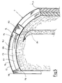
- the ring recess 16 is so in the cup foam core introduced deep and so wide (see also Fig. 4) that the Wall 7, 46, 47 can be used safely.
- the cup foam core and also the foam core of the Wall 7, 46, 47 and the armored mortar layers arranged thereon are undamaged, there is no moisture Ways to get into the substructure on the the circular shower 100 is attached.
- a substructure is first made on the raw concrete of the bathroom applied and on this the shower tray floor equipment 1 put on.
- a drain pan element inserted, which is connected to a drain line is.
- the drain pipe ends in a pipe connection element, that with the pot connection element of the drain pot element connected is.
- the pot connection element is in a seal receiving groove inserted a seal that is waterproof Connection to the drain line guaranteed.
- the opposite ones Ends of the circular wall device 7 in the area of Door recess 65 each a perforated U-profile 61, 62 glued on.
- the plastic-coated is used as an adhesive Mortar used to form the reinforced mortar layer Is used.
- the particular advantage of using it of the perforated U profiles is that the profiles not only be glued, but that the from the Holes in the U-profile with the adhesive exiting the U-profiles anchored to the wall device 7. With these U profiles then a door frame can be connected, the one door or one Door leaf or a sliding door holds. Because the U-profile is very firmly connected to the wall device 7, in contrast, tearing out or tearing off the door frame avoided to already known existing shower facilities.
- shower panel 5 and the floor panel manufactured.
- shower cladding come on the outside the wall device 7 wall outer tiles 1 and inside the Round shower wall tiles 53 for use.
- the shower tray ceiling device 3 can also use the same tiles be tiled.
- shower tray floor device is made with shower tray tiles 54 3 occupied and in the drain pot element Built-in cup holding element with a male thread and a Receiving ring element screwed so far that it either on the sub-floor element or another surface puts on and a drain grate on the drain recess 15 hung up.
- the one-piece shower tray floor equipment secures 1, the one-piece circular shower facility 7, the one-piece shower tray ceiling device 3 and the connection between the shower wall device 7 and the two cup devices, due to the Ring recess 16 and 36, for the circular shower 100 on all sides is liquid-tight. Even the slightest amount of moisture the exit to the outside is prevented. Thereby, that the devices 1, 3 and 7 completely made of coated Hard plastic foam exist, they do not lead to any massive load on the ceiling, so that the circular shower 100th especially for retrofitting existing buildings suitable.
- Another advantage of the one-piece design Facilities 1, 3 and 7 is that they are due to the mortar layers Strength properties like those cast from concrete or have parts of the circular shower 100 made of stones.
Landscapes
- Engineering & Computer Science (AREA)
- Architecture (AREA)
- Structural Engineering (AREA)
- Civil Engineering (AREA)
- Public Health (AREA)
- Health & Medical Sciences (AREA)
- Mechanical Engineering (AREA)
- General Health & Medical Sciences (AREA)
- Epidemiology (AREA)
- Ceramic Engineering (AREA)
- Chemical & Material Sciences (AREA)
- Finishing Walls (AREA)
- Building Environments (AREA)
- Forms Removed On Construction Sites Or Auxiliary Members Thereof (AREA)
- Absorbent Articles And Supports Therefor (AREA)
- Cultivation Receptacles Or Flower-Pots, Or Pots For Seedlings (AREA)
- Massaging Devices (AREA)
- Tubes (AREA)
- Percussion Or Vibration Massage (AREA)
Abstract
Description
Eine Rundwandeinrichtung ist aus der DE-C-4 100 737 bekannt. Sie besteht aus 3 - 8 Bogenelementen, die durch an den Seiten jeweils passende Nut- und Federelemente zu einer zylindrischen Röhre zusammengefügt werden. Diese Röhre wird mit einem Bodenelement mit kreisförmiger Nut und zur Mitte verlaufendem Gefälle und einem Deckelelement zu einer Runddusche zusammengefügt. In der Mitte des Bodenelements ist eine Bodenöffnung vorgesehen. Die Bogenelemente und das Bodenund Deckelelemnet werden aus einem Kunststoffhartschaum durch Schäumen oder Zuschneiden hergestellt Zur Oberflächenvestärkung wird auf das Bodenelement und die Innen- und Außenseite der Röhre eine Schicht aus glasfaserverstärktem Beton aufgebracht.
Es kann auch dadurch erleichtert werden, wenn wenigstens die erste Bogenmörtelschicht eines der Wandbogensegmente an einer Schmalseite auf dem ersten Bogenplatten-Schaumstoffkern beabstandet angeordnet wird und wenn eines der armierten Mörtelschicht- Überstandsflächenelemente auf dem Kernstreifen aufgeklebtwird.
- eine erste Schaumstoffplatte (Plattenschaumstoffkern) mit einer auf einer Flachseite aufgebrachten ersten armierten Mörtelschicht wird konkav zu einem ersten Bogenteilelement gebogen,
- eine zweite Schaumstoffplatte mit einer auf einer Flachseite aufgebrachten zweiten armierten Mörtelschicht wird konvex zu einem zweiten Bogenteilelement (Bogenteilelemnt) gebogen und
- das erste Bogenteilelement und das zweite Bogenteilelement werden mit ihren jeweils unbeschichteten Flachseiten verbunden.
- Fig. 1
- eine Runddusche mit einer Rundwandeinrichtung in einer schematischen,perspektivischen Darstellung;
- Fig. 2
- eine Runddusche gemäß Fig. 1 in einer auseinandergezogenen Darstellung;
- Fig. 3
- eine Duschtasseneinrichtung für eine Runddusche gemäß Fig. 1 in einer perspektivischen Schnittdarstellung;
- Fig. 4
- eine in eine Duschtasseneinrichtung eingesetzte Rundwandeinrichtung in einer schematisch dargestellten Teilschnitt-Darstellung;
- Fig. 5
- eine Rundwandeinrichtung gemäß den Fig. 1, 2 und 4 in einer schematischen, perspektivischen Darstellung;
- Fig. 6
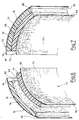
- ein Wandbogensegment für eine Rundwandeinrichtung gemäß Fig. 5 in einer teilweise auseinandergezogenen schematischen, perspektivischen Darstellung;
- Fig. 7
- ein Wandbogensegment gemäß Fig. 6 in einer zusammegesetzten schematischen, perspektivischen Darstellung und
- Fig. 8
- zwei einseitig mit einer armierten Mörtelschicht beschichtete Plattenschaumstoffkerne für eine Herstellung eines Wandbogensegments gemäß Fig. 6 und 7 in einer schematischen, auseinandergezogenen perspektivischen Darstellung.
Sie kann für Trennwände oder Eingangsbereiche in repräsentativen Gebäuden eingesetzt werden.
Die Rundwandeinrichtung ist hier als Dusch-Rundwandeinrichtung 7 Teil einer Runddusche 100, wie sie in den Figuren 1 und 2 dargestellt ist.
Es besteht aus zwei Bogenteilwänden 72, 73 aus einem Kunststoff-Hartschaum, die einseitig mit einer armierten Bogenmörtelschicht 74, 75 beschichtet sind. Die armierte Bogenmörtelschicht 74 ragt zu einer Seite als ein Mörtelschicht-Überstandsflächenelement 78 und auf der gegenüberliegenden Seite als ein Mörtelschicht-Überstandsflächenelement 84 Über. In gleicher Weise ragt die armierte Bogenmörtelschicht 75 auf der einen Seite als Mörtelschicht- Überstandsflächenelement 79 und auf der anderen Seite als ein Mörtelschicht-Überstandsflächenelement 85 über.
Es kann aber auch wenigstens eine Bogenmörtelschicht eines der Wandbogensegmente 71.1, ..., 71.n an einer Schmalseite 87, 88 auf einem Bogenplatten-Schaumstoffkern beabstandet angeordnet werden und eines der armierten Mörtelschicht-Überstandsflächenelemente auf den freien Kernstreifen aufgeklebt werden.
Beim Beschichten werden zugleich die bereits beschriebenen Mörtelschicht-Überstandsflächenelemente 78, 79, 84, 85 mit ausgebildet.
Claims (19)
- Verwendung von wenigstens einseitig mit einer armierten Mörtelschicht (740, 750) beschichteten Plattenschaumstoffkernen (760, 770) für eine Herstellung von Rundwandeinrichtungen (7) derart,
daß wenigstens ein Plattenschaumstoffkern (760, 770) mit einer mit einer auf einer Flachseite aufgebrachten ersten armierten Mörtelschicht (740, 750) zu einer Bogenteilwand (72, 73) mit einer ersten Bogenmörtelschicht (74) gebogen und auf dem zu einem Schaumstoff-Bogenflächenelement (82, 83) gebogenen anderen Flachseite (820) wenigstens eine zweite Bogenmörtelschicht (75) aufgebracht wird. - Verwendung nach Anspruch 1, dadurch gekennzeichnet,daß ein erster Plattenschaumstoffkern (760) mit der auf einer ersten Flachseite (821) aufgebrachten ersten armierten Mörtelschicht (740) konkav zu einer ersten Bogenteilwand (72) mit der ersten Bogenmörtelschicht (74) gebogen wird,daß ein zweiter Plattenschaumstoffkern (770) mit auf einer zweiten Flachseite (830) aufgebrachten zweiten armierten Mörtelschicht (750) konkav zu einer zweiten Bogenteilwand (73) mit der zweiten Bogenmörtelschicht (75) gebogen wird, unddaß eine zu einem ersten Schaumstoff-Bogenflächenelement (82) gebogene erste Flachseite (820) der ersten Bogenteilwand (72) und eine zu einem zweiten Schaumstoff-Bogenflächenelement (83) gebogene zweite Flachseite (830) der zweiten Bogenteilwand (73) miteinander zu einem Wandbogensegment (71.1,...71.n) verbunden werden.
- Verwendung nach Anspruch 1 oder 2, dadurch gekennzeichnet, daß die Wandbogensegmente (71.1, ... 71.n) an ihren Schmalseiten (87, 88) untereinander zu einer Rundwandeinrichtung verbunden werden.
- Verwendung nach einem der Ansprüche 1 bis 3, dadurch gekennzeichnet, daß die auf den ersten und den zweiten Plattenschaumstoffkern aufgebrachte erste und zweite armierte Mörtelschicht (740, 750) wenigstens teilweise mit einem armierten Mörtelschicht-Überstandsflächenelement (78, 79, 84, 85) aufgebracht wird.
- Verwendung nach einem der Ansprüche 1 bis 4 dadurch gekennzeichnet, daß beim Verbinden der Wandbogensegmente (71.1, ...) zwischen den sich gegenüberliegenden Schmalseiten (87, 88) ein Verbindungsschaumstoffkern (80) eingeklebt wird, auf dem die armierten Mörtelschicht-Überstandsflächenelemente (78, 79, 84, 85) aufgeklebt werden.
- Verwendung nach einem der Ansprüche 1 bis 5, dadurch gekennzeichnet,daß wenigstens die erste Bogenmörtelschicht eines der Wandbogensegmente (71.1, ...,71.n) an einer Schmalseite (87, 88) auf dem ersten Bogenplatten-Schaumstoffkern (76) beabstandet aufgebracht wird unddaß eines der armierten Mörtelschicht- Überstandsflächenelemente (78, 79, 84, 85) auf dem Kernstreifen aufgeklebt wird.
- Verwendung nach einem der Ansprüche 1 bis 6, dadurch gekennzeichnet, daß die aneinanderstoßenden Mörtelschicht-Überstandsflächenelemente (78, 79, 84, 85) mit einem Verbindungdichtband (81) überklebt werden.
- Verfahren zum Herstellen eines Wandbogensegments (71.1, ... 71.n) nach folgenden Verfahrensschritteneine erste Schaumstoffplatte (Plattenschaumstoffkern 760) mit einer auf einer Flachseite (821) aufgebrachten ersten armierten Mörtelschicht (740) wird konkav zu einer ersten Bogenteilwand (72) gebogen,eine zweite Schaumstoffplatte (Plattenschaumstoffkern 770) mit einer auf einer Flachseite (831) aufgebrachten zweiten armierten Mörtelschicht (750) wird konvex zu einer zweiten Bogenteilwand (73) gebogen unddie erste Bogenteilwand (72) und die zweite Bogenteilelwand (73) werden mit ihren jeweils unbeschichteten Flachseiten (820, 830) verbunden.
- Verfahren nach Anspruch 8, dadurch gekennzeichnet, daß die armierten Mörtelschichten (78, 79, 84, 85, 740, 750) über die Schaumstoffplatten (760, 770) überstehen.
- Rundwandeinrichtung (7), bestehend aus wenigstens einem Wandbogensegment (71.1, ..., 71.n) aus einem Kunststoffhartschaum, auf dem wenigstens teilweise eine Mörtelschicht mit einem Gewebe aufgebracht ist,
wobei die Wandbogensegmente (71.1, ...) an ihren Schmalseiten (87, 88) untereinander zu verbinden sind,wobei wenigstens ein Plattenschaumstoffkern (760, 770) mit einer mit einer auf einer Flachseite angeordneten ersten armierten Mörtelschicht (740, 750) zu einer Bogenteilwand (72, 73) mit einer ersten Bogenmörtelschicht (74) gebogen ist undwobei auf dem zu einem Schaumstoff-Bogenflächenelement (82, 83) gebogenen anderen Flachseite (820) wenigstens eine zweite Bogenmörtelschicht (75) aufzubringen ist. - Einrichtung nach Anspruch 10, dadurch gekennzeichnetdaß ein erster Plattenschaumstoffkern (760) mit der auf einer ersten Flachseite (821) aufgebrachten ersten armierten Mörtelschicht (740) konkav zu einer ersten Bogenteilwand (72) mit der ersten Bogenmörtelschicht (74) gebogen ist,daß ein zweiter Plattenschaumstoffkern (770) mit auf einer zweiten Flachseite (830) aufgebrachten zweiten armierten Mörtelschicht (750) konkav zu einer zweiten Bogenteilwand (73) mit der zweiten Bogenmörtelschicht (75) gebogen ist, unddaß eine zu einem ersten Schaumstoff-Bogenflächenelement (82) gebogene erste Flachseite (820) der ersten Bogenteilwand (72) und eine zu einem zweiten Schaumstoff-Bogenflächenelement (83) gebogene zweite Flachseite (830) der zweiten Bogenteilwand (73) miteinander zu einem Wandbogensegment (71.1,...71.n) verbunden sind.
- Einrichtung nach Anspruch 10 oder 11, dadurch gekennzeichnet, daß die erste und die zweite Bogenmörtelschicht (74, 75) auf wenigstens einer Schmalseite (87, 88) eines Wandbogensegments (71.1, ...) wenigstens teilweise ein armiertes Mörtelschicht-Überstandsflächenelement (78, 79, 84, 85) aufweist.
- Einrichtung nach einem der Ansprüche 10 bis 12, dadurch gekennzeichnet,daß wenigstens die erste Bogenmörtelschicht eines der Wandbogensegmente (71.1, ...,71.n) an einer Schmalseite (87, 88) auf dem ersten Bogenplatten-Schaumstoffkern (76) beabstandet angeordnet ist unddaß eines der armierten Mörtelschicht- Überstandsflächenelemente (78, 79, 84, 85) auf dem Kernstreifen aufklebbar ist.
- Einrichtung nach einem der Ansprüche 10 bis 13, dadurch gekennzeichnet,daß zwischen den Schmalseiten (87, 88) der Wandbogensegmente (71.1, ...) ein Verbindungsschaumstoffkern (80) angeordnet ist, unddaß die armierten Mörtelschicht-Überstandsflächenelemente (78, 79, 84, 85) über dem Verbindungsschaumstoffkern (80) angeordnet sind.
- Einrichtung nach einem der Ansprüche 10 bis 14, dadurch gekennzeichnet, daß über einer Stoßstelle der Mörtelschicht-Überstandsflächenelemente (78, 79, 84, 85) ein Verbindungsdichtband (81) angeordnet ist.
- Einrichtung nach einem der Ansprüche 10 bis 15, dadurch gekennzeichnet, daß die armierte Bogenmörtelschicht (74, 75) und das armierte Mörtelschicht-Überstandsflächenelement (78, 79, 84, 85) aus einem Glasfasergewebe (741, 751) besteht, das wenigstens teilweise in einer ausgehärteten Mörtelschicht (742, 752) eingebettet ist.
- Einrichtung nach Anspruch 16, dadurch gekennzeichnet, daß das Glasfasergewebe eine Maschenweite zwischen 0,25 bis 0,6 x 0,25 bis 0,6 cm und zwischen 0,4 bis 0,7 x 0,9 bis 1,1 cm aufweist.
- Einrichtung nach Anspruch 16, dadurch gekennzeichnet, daß die Mörtelschicht (742, 752) aus einem kunststoffvergüteten Zementmörtelhergestellt.
- Rundwandeinrichtung (7) unter Verwendung von mindestens zwei Wandbogensegmenten (71.1,... 71.n) nach Anspruch 8 und 9, dadurch gekennzeichnet, daß die Wandbogensegmente (71.1,... 71.n) mit ihren Schmalseiten (87, 88) über einen Verbindungsschaumstoffkern (80) verbunden sind, der zwischen den überstehenden Mörtelschichten (78, 79, 84, 85) eingeklebt ist und auf die überstehenden Mörtelschichten (78, 79, 84, 85) benachbarter Wandbogensegmente (71.1, ... 71.n) zur Fugenüberdeckung das Verbindungsdichtband (81) aufgeklebt ist.
Applications Claiming Priority (2)
| Application Number | Priority Date | Filing Date | Title |
|---|---|---|---|
| DE10060869A DE10060869C2 (de) | 2000-12-06 | 2000-12-06 | Verfahren zum Herstellen eines gebogenen Wandelements und Rundwand |
| DE10060869 | 2000-12-06 |
Publications (3)
| Publication Number | Publication Date |
|---|---|
| EP1213401A2 true EP1213401A2 (de) | 2002-06-12 |
| EP1213401A3 EP1213401A3 (de) | 2003-04-23 |
| EP1213401B1 EP1213401B1 (de) | 2005-09-07 |
Family
ID=7666174
Family Applications (1)
| Application Number | Title | Priority Date | Filing Date |
|---|---|---|---|
| EP01128871A Expired - Lifetime EP1213401B1 (de) | 2000-12-06 | 2001-12-05 | Rundwandeinrichtung |
Country Status (5)
| Country | Link |
|---|---|
| EP (1) | EP1213401B1 (de) |
| AT (1) | ATE304094T1 (de) |
| DE (2) | DE10060869C2 (de) |
| DK (1) | DK1213401T3 (de) |
| ES (1) | ES2249374T3 (de) |
Cited By (2)
| Publication number | Priority date | Publication date | Assignee | Title |
|---|---|---|---|---|
| CN102108756A (zh) * | 2011-01-11 | 2011-06-29 | 济南市住宅产业化发展中心 | 复合墙板及其生产方法和连接结构 |
| CN114743448A (zh) * | 2022-04-29 | 2022-07-12 | 山东大学 | 用于地质力学模型试验预留洞室的模型体制作装置及方法 |
Families Citing this family (1)
| Publication number | Priority date | Publication date | Assignee | Title |
|---|---|---|---|---|
| DE10204739C2 (de) * | 2001-04-28 | 2003-06-18 | Stephan Wedi | Bauplattenkörper |
Citations (5)
| Publication number | Priority date | Publication date | Assignee | Title |
|---|---|---|---|---|
| DE1629454A1 (de) | 1966-08-22 | 1971-02-04 | Prignitz Hapri Leichtbau | Verfahren und Einrichtung zur Herstellung einer Bauplatte als Strang aus Schaumstoff |
| DE3423006A1 (de) | 1984-06-22 | 1986-01-02 | Helmut 7583 Ottersweier Meister | Leichtbauteil in form von platten, pflanzkuebeln oder pflanzbehaeltern |
| DE4100737C1 (de) | 1991-01-12 | 1992-04-09 | Heidelberger Baustofftechnik Gmbh, 6900 Heidelberg, De | |
| DE4234269C1 (de) | 1992-10-10 | 1994-04-21 | Helmut Wedi | Verfahren zur Herstellung von Verbundplatten |
| EP0466163B1 (de) | 1990-07-13 | 1994-09-21 | Helmut Wedi | Halbzeug, nämlich Bauplatte oder Bauprofil aus Kunststoff-Hartschaumplatten |
Family Cites Families (3)
| Publication number | Priority date | Publication date | Assignee | Title |
|---|---|---|---|---|
| GB1175528A (en) * | 1966-11-14 | 1969-12-23 | Ici Ltd | Structural Laminate having a Foamed Core and Two Rigid Faces |
| DE3901237A1 (de) * | 1989-01-17 | 1990-07-19 | Traber Excellent Gfk Reisemobi | Verfahren zum herstellen von wandteilen fuer reisemobile |
| DE59307325D1 (de) * | 1992-10-29 | 1997-10-16 | Helmut Wedi | Verfahren zur Herstellung von Winkelhalbzeug aus Verbundplatten |
-
2000
- 2000-12-06 DE DE10060869A patent/DE10060869C2/de not_active Expired - Fee Related
-
2001
- 2001-12-05 ES ES01128871T patent/ES2249374T3/es not_active Expired - Lifetime
- 2001-12-05 EP EP01128871A patent/EP1213401B1/de not_active Expired - Lifetime
- 2001-12-05 DE DE50107352T patent/DE50107352D1/de not_active Expired - Lifetime
- 2001-12-05 DK DK01128871T patent/DK1213401T3/da active
- 2001-12-05 AT AT01128871T patent/ATE304094T1/de active
Patent Citations (5)
| Publication number | Priority date | Publication date | Assignee | Title |
|---|---|---|---|---|
| DE1629454A1 (de) | 1966-08-22 | 1971-02-04 | Prignitz Hapri Leichtbau | Verfahren und Einrichtung zur Herstellung einer Bauplatte als Strang aus Schaumstoff |
| DE3423006A1 (de) | 1984-06-22 | 1986-01-02 | Helmut 7583 Ottersweier Meister | Leichtbauteil in form von platten, pflanzkuebeln oder pflanzbehaeltern |
| EP0466163B1 (de) | 1990-07-13 | 1994-09-21 | Helmut Wedi | Halbzeug, nämlich Bauplatte oder Bauprofil aus Kunststoff-Hartschaumplatten |
| DE4100737C1 (de) | 1991-01-12 | 1992-04-09 | Heidelberger Baustofftechnik Gmbh, 6900 Heidelberg, De | |
| DE4234269C1 (de) | 1992-10-10 | 1994-04-21 | Helmut Wedi | Verfahren zur Herstellung von Verbundplatten |
Cited By (4)
| Publication number | Priority date | Publication date | Assignee | Title |
|---|---|---|---|---|
| CN102108756A (zh) * | 2011-01-11 | 2011-06-29 | 济南市住宅产业化发展中心 | 复合墙板及其生产方法和连接结构 |
| CN102108756B (zh) * | 2011-01-11 | 2012-07-04 | 济南市住宅产业化发展中心 | 复合墙板及其生产方法和连接结构 |
| CN114743448A (zh) * | 2022-04-29 | 2022-07-12 | 山东大学 | 用于地质力学模型试验预留洞室的模型体制作装置及方法 |
| CN114743448B (zh) * | 2022-04-29 | 2023-07-11 | 山东大学 | 用于地质力学模型试验预留洞室的模型体制作装置及方法 |
Also Published As
| Publication number | Publication date |
|---|---|
| EP1213401A3 (de) | 2003-04-23 |
| ES2249374T3 (es) | 2006-04-01 |
| DK1213401T3 (da) | 2006-01-16 |
| DE10060869A1 (de) | 2002-10-10 |
| EP1213401B1 (de) | 2005-09-07 |
| DE50107352D1 (de) | 2005-10-13 |
| DE10060869C2 (de) | 2003-04-30 |
| ATE304094T1 (de) | 2005-09-15 |
Similar Documents
| Publication | Publication Date | Title |
|---|---|---|
| DE3701414C2 (de) | ||
| DE3231779C2 (de) | Elastisch nachgiebige Sicherheitsbelagsplatte, insbesondere für Spielfelder | |
| EP1337725A1 (de) | Verfahren zum befestigen von wärmedämmplatten sowie dübel dafür | |
| DE19527275A1 (de) | Verfahren zur Herstellung vorgefertigter verputzter Mauerwerkswände und Schalungstisch zu dessen Durchführung | |
| EP1213401B1 (de) | Rundwandeinrichtung | |
| DE10060870C1 (de) | Runddusche | |
| EP0094662B1 (de) | Putzfassade mit Wärme-Kälte-Dämmplatten | |
| AT405666B (de) | Auf einen ebenen untergrund aufbringbare folie | |
| DE19815202A1 (de) | Dämmplatte zur Verwendung an Außenfassaden von Häusern | |
| EP0044467A1 (de) | Profiliertes Bauelement und daraus errichtetes Raumbegrenzungs- und/oder Raumunterteilungs-Baukonstruktionsteil, sowie Verfahren zur Erzeugung solcher profilierter Bauelemente | |
| DE20020711U1 (de) | Duschtasseneinrichtung | |
| CH692302A5 (de) | Flächenbelagselement und Flächenbelag, insbesondere Bodenbelag. | |
| DE202019105330U1 (de) | Eine Kunststoffplattenstruktur für den Gebäudebau | |
| DE2551597C2 (de) | Wärmedämmelemente für Gebäudeaußenwände | |
| DE3203046A1 (de) | Innendaemmung von nassraeumen und daemmplatte zu deren herstellung | |
| DE606167C (de) | Hohlwand oder Decke aus Platten, vorzugsweise Korksteinplatten | |
| DE29921970U1 (de) | Plattenelement | |
| DE4334560C2 (de) | Verfahren zum Abdichten von Böden oder Wänden | |
| DE10232855A1 (de) | Dämmstoffelement und Gebäudewand | |
| AT402418B (de) | Bauplatte und fertigteile zur errichtung von gebäuden | |
| DE3127850A1 (de) | Wandteil | |
| DE2159043C3 (de) | Wärmedämmende Verkleidungsplatte und deren Herstellungsverfahren | |
| DE19640610C1 (de) | Variables Rundbogen-Bauelement zur Altbausanierung für nicht-tragende Wände | |
| DE102019125885A1 (de) | Eine Kunststoffplattenstruktur für den Gebäudebau | |
| DE3706804A1 (de) | Platte, insbesondere bodenplatte aus beton |
Legal Events
| Date | Code | Title | Description |
|---|---|---|---|
| PUAI | Public reference made under article 153(3) epc to a published international application that has entered the european phase |
Free format text: ORIGINAL CODE: 0009012 |
|
| AK | Designated contracting states |
Kind code of ref document: A2 Designated state(s): AT BE CH CY DE DK ES FI FR GB GR IE IT LI LU MC NL PT SE TR |
|
| AX | Request for extension of the european patent |
Free format text: AL;LT;LV;MK;RO;SI |
|
| PUAL | Search report despatched |
Free format text: ORIGINAL CODE: 0009013 |
|
| AK | Designated contracting states |
Designated state(s): AT BE CH CY DE DK ES FI FR GB GR IE IT LI LU MC NL PT SE TR |
|
| AX | Request for extension of the european patent |
Extension state: AL LT LV MK RO SI |
|
| 17P | Request for examination filed |
Effective date: 20030612 |
|
| 17Q | First examination report despatched |
Effective date: 20031120 |
|
| AKX | Designation fees paid |
Designated state(s): AT BE CH CY DE DK ES FI FR GB GR IE IT LI LU MC NL PT SE TR |
|
| GRAP | Despatch of communication of intention to grant a patent |
Free format text: ORIGINAL CODE: EPIDOSNIGR1 |
|
| GRAS | Grant fee paid |
Free format text: ORIGINAL CODE: EPIDOSNIGR3 |
|
| GRAA | (expected) grant |
Free format text: ORIGINAL CODE: 0009210 |
|
| AK | Designated contracting states |
Kind code of ref document: B1 Designated state(s): AT BE CH CY DE DK ES FI FR GB GR IE IT LI LU MC NL PT SE TR |
|
| PG25 | Lapsed in a contracting state [announced via postgrant information from national office to epo] |
Ref country code: TR Free format text: LAPSE BECAUSE OF FAILURE TO SUBMIT A TRANSLATION OF THE DESCRIPTION OR TO PAY THE FEE WITHIN THE PRESCRIBED TIME-LIMIT Effective date: 20050907 Ref country code: IE Free format text: LAPSE BECAUSE OF FAILURE TO SUBMIT A TRANSLATION OF THE DESCRIPTION OR TO PAY THE FEE WITHIN THE PRESCRIBED TIME-LIMIT Effective date: 20050907 |
|
| REG | Reference to a national code |
Ref country code: GB Ref legal event code: FG4D Free format text: NOT ENGLISH |
|
| REG | Reference to a national code |
Ref country code: CH Ref legal event code: EP |
|
| REG | Reference to a national code |
Ref country code: IE Ref legal event code: FG4D Free format text: LANGUAGE OF EP DOCUMENT: GERMAN |
|
| REF | Corresponds to: |
Ref document number: 50107352 Country of ref document: DE Date of ref document: 20051013 Kind code of ref document: P |
|
| PG25 | Lapsed in a contracting state [announced via postgrant information from national office to epo] |
Ref country code: CY Free format text: LAPSE BECAUSE OF FAILURE TO SUBMIT A TRANSLATION OF THE DESCRIPTION OR TO PAY THE FEE WITHIN THE PRESCRIBED TIME-LIMIT Effective date: 20051205 |
|
| PG25 | Lapsed in a contracting state [announced via postgrant information from national office to epo] |
Ref country code: GR Free format text: LAPSE BECAUSE OF FAILURE TO SUBMIT A TRANSLATION OF THE DESCRIPTION OR TO PAY THE FEE WITHIN THE PRESCRIBED TIME-LIMIT Effective date: 20051207 |
|
| REG | Reference to a national code |
Ref country code: SE Ref legal event code: TRGR |
|
| PG25 | Lapsed in a contracting state [announced via postgrant information from national office to epo] |
Ref country code: MC Free format text: LAPSE BECAUSE OF NON-PAYMENT OF DUE FEES Effective date: 20051231 |
|
| GBT | Gb: translation of ep patent filed (gb section 77(6)(a)/1977) |
Effective date: 20051221 |
|
| REG | Reference to a national code |
Ref country code: DK Ref legal event code: T3 |
|
| REG | Reference to a national code |
Ref country code: CH Ref legal event code: NV Representative=s name: PATMED AG |
|
| REG | Reference to a national code |
Ref country code: ES Ref legal event code: FG2A Ref document number: 2249374 Country of ref document: ES Kind code of ref document: T3 |
|
| REG | Reference to a national code |
Ref country code: IE Ref legal event code: FD4D |
|
| ET | Fr: translation filed | ||
| PLBE | No opposition filed within time limit |
Free format text: ORIGINAL CODE: 0009261 |
|
| STAA | Information on the status of an ep patent application or granted ep patent |
Free format text: STATUS: NO OPPOSITION FILED WITHIN TIME LIMIT |
|
| 26N | No opposition filed |
Effective date: 20060608 |
|
| PGFP | Annual fee paid to national office [announced via postgrant information from national office to epo] |
Ref country code: DK Payment date: 20101210 Year of fee payment: 10 Ref country code: AT Payment date: 20101214 Year of fee payment: 10 |
|
| PGFP | Annual fee paid to national office [announced via postgrant information from national office to epo] |
Ref country code: GB Payment date: 20101221 Year of fee payment: 10 |
|
| REG | Reference to a national code |
Ref country code: CH Ref legal event code: NV Representative=s name: SPIERENBURG & PARTNER AG, PATENT- UND MARKENANWAEL |
|
| PGFP | Annual fee paid to national office [announced via postgrant information from national office to epo] |
Ref country code: PT Payment date: 20111205 Year of fee payment: 11 Ref country code: FR Payment date: 20120105 Year of fee payment: 11 Ref country code: CH Payment date: 20111227 Year of fee payment: 11 Ref country code: LU Payment date: 20111223 Year of fee payment: 11 Ref country code: SE Payment date: 20111223 Year of fee payment: 11 Ref country code: ES Payment date: 20111227 Year of fee payment: 11 Ref country code: FI Payment date: 20111214 Year of fee payment: 11 Ref country code: NL Payment date: 20111228 Year of fee payment: 11 |
|
| PGFP | Annual fee paid to national office [announced via postgrant information from national office to epo] |
Ref country code: BE Payment date: 20111229 Year of fee payment: 11 |
|
| PGFP | Annual fee paid to national office [announced via postgrant information from national office to epo] |
Ref country code: DE Payment date: 20111222 Year of fee payment: 11 |
|
| PGFP | Annual fee paid to national office [announced via postgrant information from national office to epo] |
Ref country code: IT Payment date: 20111228 Year of fee payment: 11 |
|
| REG | Reference to a national code |
Ref country code: PT Ref legal event code: MM4A Free format text: LAPSE DUE TO NON-PAYMENT OF FEES Effective date: 20130605 |
|
| BERE | Be: lapsed |
Owner name: *WEDI STEPHAN Effective date: 20121231 |
|
| REG | Reference to a national code |
Ref country code: NL Ref legal event code: V1 Effective date: 20130701 |
|
| PG25 | Lapsed in a contracting state [announced via postgrant information from national office to epo] |
Ref country code: SE Free format text: LAPSE BECAUSE OF NON-PAYMENT OF DUE FEES Effective date: 20121206 |
|
| REG | Reference to a national code |
Ref country code: CH Ref legal event code: PL |
|
| REG | Reference to a national code |
Ref country code: AT Ref legal event code: MM01 Ref document number: 304094 Country of ref document: AT Kind code of ref document: T Effective date: 20121205 |
|
| REG | Reference to a national code |
Ref country code: DK Ref legal event code: EBP |
|
| GBPC | Gb: european patent ceased through non-payment of renewal fee |
Effective date: 20121205 |
|
| PG25 | Lapsed in a contracting state [announced via postgrant information from national office to epo] |
Ref country code: FI Free format text: LAPSE BECAUSE OF NON-PAYMENT OF DUE FEES Effective date: 20121205 Ref country code: PT Free format text: LAPSE BECAUSE OF NON-PAYMENT OF DUE FEES Effective date: 20130605 |
|
| REG | Reference to a national code |
Ref country code: FR Ref legal event code: ST Effective date: 20130830 |
|
| PG25 | Lapsed in a contracting state [announced via postgrant information from national office to epo] |
Ref country code: BE Free format text: LAPSE BECAUSE OF NON-PAYMENT OF DUE FEES Effective date: 20121231 |
|
| REG | Reference to a national code |
Ref country code: DE Ref legal event code: R119 Ref document number: 50107352 Country of ref document: DE Effective date: 20130702 |
|
| PG25 | Lapsed in a contracting state [announced via postgrant information from national office to epo] |
Ref country code: AT Free format text: LAPSE BECAUSE OF NON-PAYMENT OF DUE FEES Effective date: 20121205 Ref country code: LI Free format text: LAPSE BECAUSE OF NON-PAYMENT OF DUE FEES Effective date: 20121231 Ref country code: CH Free format text: LAPSE BECAUSE OF NON-PAYMENT OF DUE FEES Effective date: 20121231 Ref country code: NL Free format text: LAPSE BECAUSE OF NON-PAYMENT OF DUE FEES Effective date: 20130701 Ref country code: DE Free format text: LAPSE BECAUSE OF NON-PAYMENT OF DUE FEES Effective date: 20130702 |
|
| PG25 | Lapsed in a contracting state [announced via postgrant information from national office to epo] |
Ref country code: FR Free format text: LAPSE BECAUSE OF NON-PAYMENT OF DUE FEES Effective date: 20130102 Ref country code: GB Free format text: LAPSE BECAUSE OF NON-PAYMENT OF DUE FEES Effective date: 20121205 |
|
| PG25 | Lapsed in a contracting state [announced via postgrant information from national office to epo] |
Ref country code: IT Free format text: LAPSE BECAUSE OF NON-PAYMENT OF DUE FEES Effective date: 20121205 |
|
| PG25 | Lapsed in a contracting state [announced via postgrant information from national office to epo] |
Ref country code: DK Free format text: LAPSE BECAUSE OF NON-PAYMENT OF DUE FEES Effective date: 20130102 |
|
| REG | Reference to a national code |
Ref country code: ES Ref legal event code: FD2A Effective date: 20140307 |
|
| PG25 | Lapsed in a contracting state [announced via postgrant information from national office to epo] |
Ref country code: ES Free format text: LAPSE BECAUSE OF NON-PAYMENT OF DUE FEES Effective date: 20121206 Ref country code: LU Free format text: LAPSE BECAUSE OF NON-PAYMENT OF DUE FEES Effective date: 20121205 |