EP1209665A2 - Elekronisches Gerät mit einer Vorrichtung zum Schutz eines bewegbaren Teils und Verfahren zum Schutz des bewegbaren Teils des elektronischen Gerätes - Google Patents
Elekronisches Gerät mit einer Vorrichtung zum Schutz eines bewegbaren Teils und Verfahren zum Schutz des bewegbaren Teils des elektronischen Gerätes Download PDFInfo
- Publication number
- EP1209665A2 EP1209665A2 EP01127365A EP01127365A EP1209665A2 EP 1209665 A2 EP1209665 A2 EP 1209665A2 EP 01127365 A EP01127365 A EP 01127365A EP 01127365 A EP01127365 A EP 01127365A EP 1209665 A2 EP1209665 A2 EP 1209665A2
- Authority
- EP
- European Patent Office
- Prior art keywords
- main body
- magnetic head
- electronic apparatus
- base
- signal
- Prior art date
- Legal status (The legal status is an assumption and is not a legal conclusion. Google has not performed a legal analysis and makes no representation as to the accuracy of the status listed.)
- Granted
Links
- 238000000034 method Methods 0.000 title claims description 23
- 239000004973 liquid crystal related substance Substances 0.000 description 3
- 230000001133 acceleration Effects 0.000 description 2
- 238000001514 detection method Methods 0.000 description 2
- 238000013500 data storage Methods 0.000 description 1
- 238000006073 displacement reaction Methods 0.000 description 1
- 230000000694 effects Effects 0.000 description 1
- 230000002093 peripheral effect Effects 0.000 description 1
- 230000004044 response Effects 0.000 description 1
Images



Classifications
-
- G—PHYSICS
- G11—INFORMATION STORAGE
- G11B—INFORMATION STORAGE BASED ON RELATIVE MOVEMENT BETWEEN RECORD CARRIER AND TRANSDUCER
- G11B5/00—Recording by magnetisation or demagnetisation of a record carrier; Reproducing by magnetic means; Record carriers therefor
- G11B5/48—Disposition or mounting of heads or head supports relative to record carriers ; arrangements of heads, e.g. for scanning the record carrier to increase the relative speed
- G11B5/54—Disposition or mounting of heads or head supports relative to record carriers ; arrangements of heads, e.g. for scanning the record carrier to increase the relative speed with provision for moving the head into or out of its operative position or across tracks
-
- G—PHYSICS
- G11—INFORMATION STORAGE
- G11B—INFORMATION STORAGE BASED ON RELATIVE MOVEMENT BETWEEN RECORD CARRIER AND TRANSDUCER
- G11B19/00—Driving, starting, stopping record carriers not specifically of filamentary or web form, or of supports therefor; Control thereof; Control of operating function ; Driving both disc and head
- G11B19/02—Control of operating function, e.g. switching from recording to reproducing
- G11B19/04—Arrangements for preventing, inhibiting, or warning against double recording on the same blank or against other recording or reproducing malfunctions
-
- G—PHYSICS
- G11—INFORMATION STORAGE
- G11B—INFORMATION STORAGE BASED ON RELATIVE MOVEMENT BETWEEN RECORD CARRIER AND TRANSDUCER
- G11B21/00—Head arrangements not specific to the method of recording or reproducing
- G11B21/02—Driving or moving of heads
- G11B21/12—Raising and lowering; Back-spacing or forward-spacing along track; Returning to starting position otherwise than during transducing operation
Definitions
- the present invention relates to an electronic apparatus with an apparatus for protecting a movable section and a method of protecting the movable section of the electronic apparatus. More particularly, the invention relates to electronic apparatus with an apparatus for protecting a movable section, such as a magnetic recording unit, which is incorporated in a movable thin main body.
- a magnetic head moves over a magnetic disk rotating at high speed, without contacting the disk, to record data on and read data from the magnetic disk. While operating, the magnetic head may contact the magnetic disk when it is accelerated or receives an external force such as an impact. If this happens, the magnetic disk is damaged. Such damage develops to the periphery of the disk due to the high-speed rotation of the disk, making it impossible to use the disk normally thereafter in some cases.
- Computers including an LCD (Liquid Crystal Display) unit each are known.
- the user can turn the LCD unit to the left and the right and up and down so that he or she can see the LCD screen well.
- a movable section that is formed integral with the LCD unit may incorporate a magnetic disk drive.
- the magnetic disk provided in the disk drive receives such an impact as described above, when the LCD unit is moved while the magnetic disk drive is being accessed. There is the risk of destroying the data recorded on the magnetic disk. In view of this risk, it is difficult to arrange the magnetic disk drive in the back of the LCD unit.
- the data on the disk may be destroyed when the movable section of the computer is moved while magnetic disk drive (HDD) is being accessed.
- HDD magnetic disk drive
- the existing technical level cannot help but provide computers that have a movable section each, which can be moved only while no power is being supplied to the computer main body.
- the user of the computer may operate the LCD unit, by mistake, while the HDD is being accessed, possibly damaging the HDD. To obviate such a damage, the HDD cannot be provided in the LCD unit. This restricts the design layout of the computer.
- JP-A-9-16284 discloses a notebook-type personal computer having an LCD unit that can be rotated.
- the notebook-type personal computer includes a main body having a keyboard, and the LCD unit that displays the image represented by an image signal supplied from the main body.
- the personal computer further includes means configured to rotate the LCD unit in horizontal direction and an electrode section configured to keep the LCD unit electrically connected to the main body whenever the LCD unit is rotated.
- the LCD unit of this notebook-type personal computer can be rotated though any desired angle to display images to the user of the computer.
- the main body of the computer need not be moved to enable the user to see images in the best possible manner.
- Japanese Patent Publication No. 2629548 discloses a protection mechanism for protecting a magnetic disk drive.
- the protection mechanism is designed for use in mobile, terminals.
- the protection mechanism includes a plurality of pressure sensors and save control means.
- the pressure sensors are spaced apart from one another, below the magnetic disk drive provided in a mobile terminal. They cooperate to detect a displacement of the magnetic disk drive in the form of a change in the weight (pressure) of the magnetic disk, by virtue of the gyromagnetic effect of the rotating recording medium.
- the save control means receives detection signals output from the pressure sensors and determines, from the detection signals, that the magnetic disk has inclined. Upon determining the inclining of the disk, the save control means moves the magnetic head to a save area.
- the protection mechanism detects that the user has, by mistake, inclined or dropped the mobile terminal while the mobile terminal is operating.
- the mechanism immediately moves the magnetic head to the save area, thus preventing damages to the magnetic disk drive.
- JP-A-10-232726 discloses a desktop computer.
- the desktop computer includes a display, a main body and an input unit.
- the display is a thin one provided on the upper surface of the main body and can be inclined and moved in horizontal direction.
- the desktop computer is small and light. The user can see the data displayed on the screen, not only from the front, but also from either side or the back.
- JP-A- 7-130115 discloses a data-processing apparatus.
- the data-processing apparatus is a portable one, which includes detecting means and protection means.
- the detecting means detects that the acceleration of the main body of the apparatus has already exceeded a predetermined value.
- the protection means is activated to protect the main body of the data-processing apparatus.
- the publication describes that, in the data-processing apparatus, the hard disk drive and the like are protected and the contents of the volatile memory can be saved if and when the user applies, by error, an abrupt vibration or an excessive impact to the mobile, thin data-processing apparatus.
- JP-A-6-275002 discloses a protection device for use in hard disk drives.
- the protection device is designed for hard disk drives, in which a hard disk, i.e., a magnetic recording disk, is rotated and a magnetic head is moved in the radial direction of the disk to record data on, and reproduce data from, the magnetic disk.
- the protection device includes at least a detector and protection control means.
- the detector detects an external force, such as vibration or impact that is applied in the axis of the hard disk.
- the protection control means causes the magnetic head to stop outputting or receiving signals, in response to a signal the detector has generated. Also does the protection control means move the magnetic head from a recording/reproducing region on the hard disk.
- the protection device for protecting the hard disk drive is mounted in a small apparatus such as an electronic still camera and can prevent a head clash that may otherwise result from vibration or an external force.
- JP-A-8-221886 discloses a data-recording apparatus.
- the apparatus disclosed in this publication includes a head section, a main body, a speed-detecting section, and head-withdrawing means.
- the head section can record and reproduce data on and from a recording medium.
- the main body incorporates the head section.
- the speed-detecting section detects the speed at which the main body moves.
- the head-withdrawing means moves the head section to a save area remote from the recording area of the recording medium, if the speed detected by the speed-detecting section exceeds a reference speed Vs.
- any recording region of the recording medium would not damaged in the data-recording apparatus, even if the data-recording apparatus received such a great impact as it may gets when it is dropped. Data can therefore be recorded as is desired.
- JP-A-11-345041 discloses a notebook-type personal computer.
- This notebook-type personal computer includes a main body, a display unit and a keyboard.
- the main body incorporates CPU and peripheral devices.
- the display unit can be folded onto the main body.
- the keyboard is removably connected to the main body by a magnet.
- the display unit of this notebook-type personal computer can be arranged so that the user may well see the data displayed.
- the keyboard of the notebook-type personal computer can be positioned so that the user may operate it well.
- an object of the present invention is to provide an electronic apparatus with an apparatus for protecting a movable section, which is not limited by the design layout of the electronic apparatus that includes an HDD incorporated in the movable section.
- Another object of the present invention is to provide an electronic apparatus with an apparatus for protecting a movable section, which is compact and hard to receive damage.
- Still another object of the present invention is to provide an electronic apparatus with an apparatus for protecting a movable section, of which users can move a display unit without giving any damage.
- Yet still another object of the present invention is to provide a method of protecting the movable section of the electronic apparatus, which is for the electronic apparatus that includes an HDD incorporated in the movable section.
- the present invention provides an electronic apparatus including: a base; a main body rotatably supported on the base; and a lock mechanism which prevents the main body from rotating with respect to the base, wherein the main body includes: a magnetic disk drive, wherein the magnetic disk drive includes: a magnetic head which accesses a recording medium; and a safety unit that moves the magnetic head to a save position where the magnetic head is safe in the magnetic disk drive, when the lock mechanism is unlocked.
- the safety unit may move the magnetic head to start a seeking operation over the recording medium, when the lock mechanism is locked.
- the main body may further include a display unit.
- the lock mechanism may include: a control unit which supplies a first control signal showing that the lock mechanism is unlocked to the safety unit, wherein the safety unit may supplies a first safety signal to move the magnetic head to the save position.
- control unit may supply a second control signal showing that the lock mechanism is locked to the safety unit
- safety unit may supply a second safety signal to move the magnetic head to start a seeking operation over the recording medium
- the lock mechanism may be manually operable.
- the lock mechanism may further include: a first engagement section coupled to the main body; and a second engagement section coupled to the base, wherein the base may include: a switch that is manually operable wherein the switch outputs a first unlock signal to the safety unit to move the magnetic head to the save position, and outputs a second unlock signal to unlock the first engagement section or the second engagement section from the main body or the base, when the lock mechanism is unlocked.
- the switch may output a first lock signal to the safety unit to moves the magnetic head to start a seeking operation over the recording medium, and may output a second lock signal to lock the first engagement section or the second engagement section to the main body or the base, when the lock mechanism is locked.
- the first and second lock signals may be off-signals.
- the present invention provides a method of protecting a movable section, including the steps of: (a) detecting whether or not a main body is unlocked from a base of an electronic apparatus which includes: the base; and the main body movably with respect to the base, wherein the main body includes: a display unit; and a magnetic disk drive , wherein the magnetic disk drive includes : a magnetic head; and a recording medium; (b) suspending a seeking operation of the magnetic head over the recording medium, when the main body is unlocked from the base; and (c) moving the magnetic head to a save position where the magnetic head is safe in the magnetic disk drive.
- the (a) detecting step includes the steps of: (d) generating automatically a first control signal when the main body is unlocked from the base; and (e) sending the first control signal to the magnetic disk drive, wherein the (b) suspending step suspends the seeking operation based on the first control signal.
- the method further includes the steps of: (f) detecting whether or not the magnetic head lies in the save position, when the main body is locked to the base; (g) moving the magnetic head over the recording medium when the magnetic head lies in the save position; and (h) starting a seeking operation of the magnetic head.
- the (f) detecting step includes the steps of: (i) generating automatically a second control signal when the main body is locked to the base; and (j) sending the second control signal to the magnetic disk drive, wherein the (g) moving step moves the magnetic head over the recording medium based on the second control signal.
- the (a) detecting step includes the steps of: (k) generating automatically an unlock signal when the main body is unlocked from the base by turning on a switch; and (l) sending the unlock signal to the magnetic disk drive, wherein the (b) suspending step suspends the seeking operation based on the unlock signal, and the base includes the switch.
- the (f) detecting step includes the steps of: (m) generating automatically a unlock signal when the main body is locked to the base by turning off the switch; and (n) sending the unlock signal to the magnetic disk drive, wherein the (g) moving step moves the magnetic head over the recording medium based on the unlock signal.
- the (g) moving step includes the step of: (o) letting a predetermined time elapse after the main body is locked to the base.
- An electronic apparatus of the first embodiment is a desktop personal computer illustrated in FIG. 1 and includes an LCD (Liquid Crystal Display).
- FIG. 1 shows the desktop personal computer includes a main body 1 and a base 2.
- the main body 1 is movably supported on the base 2 by a support mechanism.
- the support mechanism includes a base-side shaft 3 and a body-side shaft 4.
- the base-side shaft 3 is secured to the base 2 and can rotate.
- the body-side shaft 4 is secured to the main body 1.
- the body side shaft 4 is supported on the base-side shaft 3 and can rotate.
- a lock mechanism 5 is interposed between the base-side shaft 3 and the body-side shaft 4.
- the main body 1 can be rotated clockwise and counterclockwise directions X around the first axis L1 of the body-side shaft 4 as is illustrated in FIG. 2.
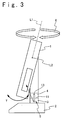
- the main body 1 can be rotated in the direction Y around the second axis L2 as is illustrated in FIG. 3.
- the main body 1 can therefore rotate in a horizontal plane and a vertical plane.
- the second axis L2 intersects with the first axis L1 at right angles.
- the lock mechanism 5 includes a lock arm 6 and a lock groove 7.
- the lock arm 6 is connected to the base-side shaft 3 and can rotate.
- the lock groove 7 is cut in the body-side shaft 4.
- the lock arm 6 has a proximal end 8 as a second engagement section having a control unit, which is coupled to the base-side shaft 3.
- the lock arm 6 has an engaging end 9 as a first engagement section, which can fit into the lock groove 7 to lock the body-side shaft 4 to the base-side shaft 3.
- the user rotates the lock arm 6 around the proximal end 8 that acts as a fulcrum, as is indicated by the broken lines in FIG. 1.
- the engaging end 9 of the arm 6 is thereby pulled out of the lock groove 7.
- the main body 1 includes an LCD 11 as a display unit and incorporates an HDD (Hard Disk Drive) 12 as a magnetic disk drive.
- the HDD 12 includes a recording medium 13, a magnetic head 14, a CPU 15 as a safety unit, a spindle motor 16, and a save zone (shipping zone) 17 as a save position.
- the magnetic head 14 can write and read data on and from the recording medium 13.
- the CPU 15 controls the motion of the magnetic head 14.
- the spindle motor 16 is provided to move the magnetic head 14.
- the magnetic head 14 can be moved from any position over the medium 13 into the save zone 17.
- FIG. 4 is a flowchart that explains a method of protecting a movable section of an electronic apparatus, according to the present invention.
- the user of the computer may rotate the main body 1 in the directions X and Y while using the computer.
- the HDD 12 incorporated in the main body 1 is moved and vibrated at the same time.
- the magnetic head 14 may come into physical contact with the recording medium 13, possibly destroying the recording medium 13. Nonetheless, the recording medium 13 would not be destroyed.
- the user cannot rotate the main body 1 unless the user rotates the lock arm 6 around the proximal end 8 thereof, thus pulling the engaging end 9 of the arm 6 from the lock groove 7 cut in the body-side shaft 4.
- a sensor as a control unit, provided at the proximal end 8 detects this fact and generates a first control signal 18 (Step S1).
- the first control signal 18 is supplied to the CPU 15 incorporated in the HDD 12.
- the CPU 15 suspends the seeking operation of the magnetic head 14 by supplying a first safety signal 19 to the spindle motor 16 (Step S2).
- the CPU 15 then causes the spindle motor 16 to move the magnetic head 14 from a position over the medium 13 into the shipping zone 17 (Step S3).
- the data being written on, or read from, the medium 13 at this time is temporarily saved.
- Step S1 When the user locks the main body 1 to the base 2, the sensor at the proximal end 8 stops generating the first control signal 18. It means that the CPU 15 receives a second control signal 18' which is an off-signal of the first control signal 18 (Step S1). Then, it is determined whether the magnetic head 14 lies in the shipping zone 17 (Step S4). If YES in Step S4, the CPU 15 does nothing until a predetermined time passes (Step S5). Upon lapse of the predetermined time, the CPU 15 drives the spindle motor 16, moving the magnetic head 14 from the shipping zone 17 back to the position over the recording medium 13 by supplying a second safety signal 19' to the spindle motor 16 (Step S6). The CPU 15 then resumes the seeking operation of the magnetic head 14 (Step S7). The magnetic head 14 writes the data, which is temporarily saved, on the recording medium 13, or stores this data into a data-storage device.
- Step S4 the process returns to Step S1. That is, if the LCD 11 is not operated and the magnetic head 14 does not lie in the shipping zone 17, the process repeats itself.
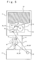
- FIG. 5 shows an electronic apparatus that is the second embodiment of the present invention.
- the second embodiment differs from the first embodiment in that an electric motor drives the proximal end 8 of the lock arm 6.
- a lock-unlocking switch 21 is provided on the base 2.
- a second unlock signal 22 is generated and actuates the electric motor.
- the electric motor rotates the lock arm 6 to the position indicated by the broken lines (FIG. 5), unlocking the lock mechanism 5.
- the user may push the switch 21 to stop generating the second unlock signal 22. It means that the electric motor receives a second lock signal 22' which is an off-signal of the second unlock signal 22. Then, the electric motor rotates the lock arm 6 in the opposite direction, pushing the engaging end 9 of the arm 6 into the lock groove 7.
- a first unlock signal 23 generated is supplied to the CPU 15 of the HDD 12 at the same time of supplying the second unlock signal 22.
- the CPU 15 suspends the seeking operation of the magnetic head 14.
- the CPU 15 then causes the spindle motor 16 to move the magnetic head 14 from a position over the medium 13 into the shipping zone 17.
- the lock-unlocking switch 21 stops supplying the first unlock signal 23. It means that the CPU 15 receives a first lock signal 23' which is an off-signal of the first unlock signal 23. Hence, the CPU 15 does nothing until a predetermined time passes.
- the CPU 15 drives the spindle motor 16, moving the magnetic head 14 from the shipping zone 17 back to the position over the recording medium 13.
- the CPU 15 then resumes the seeking operation of the magnetic head 14. Data can therefore be written or read in the HDD 12.
- the lock arm 6 has its engaging end 9 fitted in the lock groove 7, the main body 1 remains locked mechanically or electrically and cannot rotate around the second axis L2, either.
- the motor is driven to lock or unlock the first engagement section to or from the main body, when the user operates the switch 21.
- the switch 21 unless the user operates the switch 21, the main body 1 will not be locked to, or unlocked from, the base 2.
- the first unlock signal 23 and the second unlock signal 22 are on-signals, while the first lock signal 23' and the second lock signal 22' are off-signals.
- the second unlock signal 22 can unlock the main body 1 from the base 2.
- the first unlock signal 23 and the second unlock signal 22 automatically generated are generated by operating the same switch 21, when the main body 1 is unlocked.
- the lock mechanism 5 Unless the lock mechanism 5 is unlocked, the user cannot move the main body 1 at all.
- the magnetic head 14 has already moved from the recording medium 13 to the save zone 17. Hence, the magnetic head 14 is prevented from contacting the recording medium 13 when the main body 1 is moved. This prevents damages to the recording medium 13. The user can therefore move the main body 1, without worrying about any possible troubles.
- the motion of the main body may greatly vibrate the magnetic head with respect to the magnetic recording medium, or vice versa, depending on the positional relation between the head and the medium.
- the present invention effectively works, particularly in such computers.
- the electronic apparatus with an apparatus for protecting a movable section of the electronic apparatus and method for protecting a movable section, both according to the present invention enable the user of the electronic apparatus, including a TV, DVD and video player with HDD and so on, to move the main body of the electronic apparatus, without the risk of causing troubles.
- the invention therefore makes it possible to incorporate an HDD into the movable section.
- a magnetic disk drive can be incorporated into the movable section of a computer, which includes a thin display, regardless of the design layout the computer.
Landscapes
- Moving Of Heads (AREA)
- Storage Device Security (AREA)
- Casings For Electric Apparatus (AREA)
- Holding Or Fastening Of Disk On Rotational Shaft (AREA)
Applications Claiming Priority (2)
| Application Number | Priority Date | Filing Date | Title |
|---|---|---|---|
| JP2000360143A JP3487822B2 (ja) | 2000-11-27 | 2000-11-27 | 電子機器運動部位の保護装置、及び、その保護方法 |
| JP2000360143 | 2000-11-27 |
Publications (3)
| Publication Number | Publication Date |
|---|---|
| EP1209665A2 true EP1209665A2 (de) | 2002-05-29 |
| EP1209665A3 EP1209665A3 (de) | 2008-05-28 |
| EP1209665B1 EP1209665B1 (de) | 2009-01-21 |
Family
ID=18831790
Family Applications (1)
| Application Number | Title | Priority Date | Filing Date |
|---|---|---|---|
| EP01127365A Expired - Lifetime EP1209665B1 (de) | 2000-11-27 | 2001-11-21 | Elekronisches Gerät mit einer Vorrichtung zum Schutz eines bewegbaren Teils und Verfahren zum Schutz des bewegbaren Teils des elektronischen Gerätes |
Country Status (3)
| Country | Link |
|---|---|
| US (1) | US6816333B2 (de) |
| EP (1) | EP1209665B1 (de) |
| JP (1) | JP3487822B2 (de) |
Cited By (2)
| Publication number | Priority date | Publication date | Assignee | Title |
|---|---|---|---|---|
| EP1569221A1 (de) * | 2004-02-26 | 2005-08-31 | Kabushiki Kaisha Toshiba | Tragbares Informationsendgerät und Steuerungsverfahren für tragbares Informationsendgerät |
| EP1927985A3 (de) * | 2006-11-30 | 2008-09-10 | Kabushiki Kaisha Toshiba | Informationsverarbeitungsvorrichtung |
Families Citing this family (2)
| Publication number | Priority date | Publication date | Assignee | Title |
|---|---|---|---|---|
| JP4705914B2 (ja) * | 2004-05-27 | 2011-06-22 | 出光興産株式会社 | 非対称ピレン誘導体及びそれを利用した有機エレクトロルミネッセンス素子 |
| US9070007B2 (en) * | 2013-01-11 | 2015-06-30 | Datalogic ADC, Inc. | Adjustable data reader with pivot mount |
Family Cites Families (19)
| Publication number | Priority date | Publication date | Assignee | Title |
|---|---|---|---|---|
| US5122914A (en) * | 1984-01-17 | 1992-06-16 | Norand Corporation | Disk drive system with transportable carrier and mounting assembly |
| US4669053A (en) * | 1984-05-31 | 1987-05-26 | Zenith Electronics Corporation | Portable personal computer |
| GB2200783B (en) * | 1987-01-15 | 1991-01-16 | Compaq Computer Corp | Adjustable display panel for portable computer |
| JPH02148114A (ja) * | 1988-11-30 | 1990-06-07 | Nippon I B M Kk | パーソナル・コンピュータ |
| US5247285A (en) * | 1992-03-06 | 1993-09-21 | Everex Systems, Inc. | Standup portable personal computer with detachable wireless keyboard and adjustable display |
| JP2629548B2 (ja) | 1993-01-05 | 1997-07-09 | 日本電気株式会社 | 磁気ディスク装置の保護機構 |
| JP3223359B2 (ja) | 1993-03-18 | 2001-10-29 | 京セラ株式会社 | ハ−ドディスク記録再生機の保護装置 |
| JPH07130115A (ja) | 1993-11-08 | 1995-05-19 | Toshiba Corp | 情報処理装置 |
| JPH08138307A (ja) * | 1994-09-16 | 1996-05-31 | Toshiba Corp | 情報記憶装置 |
| JPH08221886A (ja) | 1995-02-16 | 1996-08-30 | Sanyo Electric Co Ltd | データ記録装置 |
| JPH0916284A (ja) | 1995-06-28 | 1997-01-17 | Nec Niigata Ltd | Lcd回転式ノート型パーソナルコンピュータ |
| US5764480A (en) * | 1996-09-23 | 1998-06-09 | International Business Machines Corporation | Computer system having a latching drive housing which pivots on hinge pins between an open position wherein a DASD is accessible and a closed position wherein the DASD is not accessible |
| JPH10222244A (ja) * | 1997-02-07 | 1998-08-21 | Hitachi Ltd | デスクトップ型コンピュータ |
| JPH10232736A (ja) | 1997-02-19 | 1998-09-02 | Hitachi Seiko Ltd | 座標検出装置 |
| JPH11345041A (ja) | 1998-06-01 | 1999-12-14 | Nec Corp | ノート型パソコン |
| US6256193B1 (en) * | 1998-09-22 | 2001-07-03 | Speck Product Design, Inc. | Vertical docking and positioning apparatus for a portable computer |
| US6216999B1 (en) * | 1998-11-05 | 2001-04-17 | Apple Computer, Inc. | Floating mount and method for mounting a device to a chassis thereby |
| US6549416B2 (en) * | 2001-03-15 | 2003-04-15 | Hewlett Packard Development Company, L.P. | Portable computer docking station with protected connector |
| US6680843B2 (en) * | 2001-09-28 | 2004-01-20 | International Business Machines Corporation | All-in-one personal computer with tool-less quick-release features for various elements thereof including a reusable thin film transistor monitor |
-
2000
- 2000-11-27 JP JP2000360143A patent/JP3487822B2/ja not_active Expired - Fee Related
-
2001
- 2001-11-21 EP EP01127365A patent/EP1209665B1/de not_active Expired - Lifetime
- 2001-11-26 US US09/991,717 patent/US6816333B2/en not_active Expired - Fee Related
Non-Patent Citations (1)
| Title |
|---|
| No relevant documents disclosed * |
Cited By (2)
| Publication number | Priority date | Publication date | Assignee | Title |
|---|---|---|---|---|
| EP1569221A1 (de) * | 2004-02-26 | 2005-08-31 | Kabushiki Kaisha Toshiba | Tragbares Informationsendgerät und Steuerungsverfahren für tragbares Informationsendgerät |
| EP1927985A3 (de) * | 2006-11-30 | 2008-09-10 | Kabushiki Kaisha Toshiba | Informationsverarbeitungsvorrichtung |
Also Published As
| Publication number | Publication date |
|---|---|
| US20020063988A1 (en) | 2002-05-30 |
| EP1209665B1 (de) | 2009-01-21 |
| JP2002170350A (ja) | 2002-06-14 |
| US6816333B2 (en) | 2004-11-09 |
| EP1209665A3 (de) | 2008-05-28 |
| JP3487822B2 (ja) | 2004-01-19 |
Similar Documents
| Publication | Publication Date | Title |
|---|---|---|
| US6101062A (en) | Method and apparatus for unloading head from disk before a shock to a disk drive system | |
| JP3679328B2 (ja) | コンピュータシステム、ハードディスクドライブ及びデータのセキュリティ方法 | |
| JP4564685B2 (ja) | 画像表示装置 | |
| EP1209665B1 (de) | Elekronisches Gerät mit einer Vorrichtung zum Schutz eines bewegbaren Teils und Verfahren zum Schutz des bewegbaren Teils des elektronischen Gerätes | |
| JP4927515B2 (ja) | ハードディスクドライブのパーキングランプ、及びこれを備えたハードディスクドライブ | |
| JP2002259066A (ja) | 情報処理装置 | |
| JP2629548B2 (ja) | 磁気ディスク装置の保護機構 | |
| US20070013805A1 (en) | Method and apparatus for protecting mechanical lens of cameras using miniature hard drive as gyro sensor | |
| US20070030586A1 (en) | Apparatus and method for hard disk protection | |
| JPH10187276A (ja) | 記憶装置接続構造 | |
| JP4179551B2 (ja) | 耐衝撃機器 | |
| JPH0460956A (ja) | ハードディスク搭載機器の保護装置 | |
| CN101471121B (zh) | 光盘装置及电子设备 | |
| JPH02292774A (ja) | 電子機器 | |
| JP3239771B2 (ja) | ディスク装置 | |
| EP0749113B1 (de) | Magnetplatteneinheit mit einem schlagkraftanwendenden Mechanismus | |
| JP4376126B2 (ja) | スタンド機構及び電子機器 | |
| JP4266112B2 (ja) | 記録再生装置 | |
| JP4651698B2 (ja) | 記録再生装置 | |
| JP2008247306A (ja) | 傾動式表示装置付電子機器、その制御方法及び制御プログラム | |
| JP2002109873A (ja) | ディスク装置及びその制御方法 | |
| JPH05135530A (ja) | 磁気デイスク装置 | |
| EP1586972A2 (de) | Datenträgereinrichtung, verfahren zur steuerung einer datenträgereinrichtung, programm und aufzeichnungsmedium | |
| JPH0845203A (ja) | ディスク装置 | |
| JP2001035101A (ja) | 磁気ディスク装置の保護機能 |
Legal Events
| Date | Code | Title | Description |
|---|---|---|---|
| PUAI | Public reference made under article 153(3) epc to a published international application that has entered the european phase |
Free format text: ORIGINAL CODE: 0009012 |
|
| AK | Designated contracting states |
Kind code of ref document: A2 Designated state(s): AT BE CH CY DE DK ES FI FR GB GR IE IT LI LU MC NL PT SE TR |
|
| AX | Request for extension of the european patent |
Free format text: AL;LT;LV;MK;RO;SI |
|
| PUAL | Search report despatched |
Free format text: ORIGINAL CODE: 0009013 |
|
| AK | Designated contracting states |
Kind code of ref document: A3 Designated state(s): AT BE CH CY DE DK ES FI FR GB GR IE IT LI LU MC NL PT SE TR |
|
| AX | Request for extension of the european patent |
Extension state: AL LT LV MK RO SI |
|
| RIC1 | Information provided on ipc code assigned before grant |
Ipc: G11B 19/04 20060101ALI20080421BHEP Ipc: G11B 5/54 20060101AFI20080421BHEP Ipc: G11B 21/02 20060101ALI20080421BHEP Ipc: G11B 33/12 20060101ALI20080421BHEP |
|
| 17P | Request for examination filed |
Effective date: 20080506 |
|
| GRAP | Despatch of communication of intention to grant a patent |
Free format text: ORIGINAL CODE: EPIDOSNIGR1 |
|
| REG | Reference to a national code |
Ref country code: DE Ref legal event code: 8566 |
|
| GRAS | Grant fee paid |
Free format text: ORIGINAL CODE: EPIDOSNIGR3 |
|
| GRAA | (expected) grant |
Free format text: ORIGINAL CODE: 0009210 |
|
| AK | Designated contracting states |
Kind code of ref document: B1 Designated state(s): FR |
|
| AKX | Designation fees paid |
Designated state(s): FR |
|
| PLBE | No opposition filed within time limit |
Free format text: ORIGINAL CODE: 0009261 |
|
| STAA | Information on the status of an ep patent application or granted ep patent |
Free format text: STATUS: NO OPPOSITION FILED WITHIN TIME LIMIT |
|
| 26N | No opposition filed |
Effective date: 20091022 |
|
| REG | Reference to a national code |
Ref country code: FR Ref legal event code: TP Owner name: NEC PERSONAL COMPUTERS, LTD, JP Effective date: 20111024 |
|
| REG | Reference to a national code |
Ref country code: FR Ref legal event code: PLFP Year of fee payment: 15 |
|
| REG | Reference to a national code |
Ref country code: FR Ref legal event code: PLFP Year of fee payment: 16 |
|
| REG | Reference to a national code |
Ref country code: FR Ref legal event code: PLFP Year of fee payment: 17 |
|
| PGFP | Annual fee paid to national office [announced via postgrant information from national office to epo] |
Ref country code: FR Payment date: 20171012 Year of fee payment: 17 |
|
| PG25 | Lapsed in a contracting state [announced via postgrant information from national office to epo] |
Ref country code: FR Free format text: LAPSE BECAUSE OF NON-PAYMENT OF DUE FEES Effective date: 20181130 |