EP1202000A2 - Heizgerät mit integriertem Ausdehnungsgefäss - Google Patents
Heizgerät mit integriertem Ausdehnungsgefäss Download PDFInfo
- Publication number
- EP1202000A2 EP1202000A2 EP01123017A EP01123017A EP1202000A2 EP 1202000 A2 EP1202000 A2 EP 1202000A2 EP 01123017 A EP01123017 A EP 01123017A EP 01123017 A EP01123017 A EP 01123017A EP 1202000 A2 EP1202000 A2 EP 1202000A2
- Authority
- EP
- European Patent Office
- Prior art keywords
- wall
- housing
- expansion vessel
- heater
- shell
- Prior art date
- Legal status (The legal status is an assumption and is not a legal conclusion. Google has not performed a legal analysis and makes no representation as to the accuracy of the status listed.)
- Ceased
Links
- 238000010438 heat treatment Methods 0.000 claims abstract 6
- 239000002184 metal Substances 0.000 claims description 7
- 239000008236 heating water Substances 0.000 claims description 3
- 239000012528 membrane Substances 0.000 abstract description 7
- XLYOFNOQVPJJNP-UHFFFAOYSA-N water Substances O XLYOFNOQVPJJNP-UHFFFAOYSA-N 0.000 abstract description 2
- IJGRMHOSHXDMSA-UHFFFAOYSA-N Atomic nitrogen Chemical compound N#N IJGRMHOSHXDMSA-UHFFFAOYSA-N 0.000 description 4
- 230000008901 benefit Effects 0.000 description 4
- 239000011324 bead Substances 0.000 description 3
- 238000002485 combustion reaction Methods 0.000 description 3
- 239000007789 gas Substances 0.000 description 2
- 229910052757 nitrogen Inorganic materials 0.000 description 2
- 230000015572 biosynthetic process Effects 0.000 description 1
- 238000004061 bleaching Methods 0.000 description 1
- 238000010276 construction Methods 0.000 description 1
- 238000011161 development Methods 0.000 description 1
- 230000018109 developmental process Effects 0.000 description 1
- 238000005516 engineering process Methods 0.000 description 1
- 238000004519 manufacturing process Methods 0.000 description 1
- 238000009423 ventilation Methods 0.000 description 1
Images
Classifications
-
- F—MECHANICAL ENGINEERING; LIGHTING; HEATING; WEAPONS; BLASTING
- F24—HEATING; RANGES; VENTILATING
- F24D—DOMESTIC- OR SPACE-HEATING SYSTEMS, e.g. CENTRAL HEATING SYSTEMS; DOMESTIC HOT-WATER SUPPLY SYSTEMS; ELEMENTS OR COMPONENTS THEREFOR
- F24D3/00—Hot-water central heating systems
- F24D3/10—Feed-line arrangements, e.g. providing for heat-accumulator tanks, expansion tanks ; Hydraulic components of a central heating system
- F24D3/1008—Feed-line arrangements, e.g. providing for heat-accumulator tanks, expansion tanks ; Hydraulic components of a central heating system expansion tanks
- F24D3/1016—Tanks having a bladder
-
- F—MECHANICAL ENGINEERING; LIGHTING; HEATING; WEAPONS; BLASTING
- F24—HEATING; RANGES; VENTILATING
- F24D—DOMESTIC- OR SPACE-HEATING SYSTEMS, e.g. CENTRAL HEATING SYSTEMS; DOMESTIC HOT-WATER SUPPLY SYSTEMS; ELEMENTS OR COMPONENTS THEREFOR
- F24D3/00—Hot-water central heating systems
- F24D3/10—Feed-line arrangements, e.g. providing for heat-accumulator tanks, expansion tanks ; Hydraulic components of a central heating system
- F24D3/1008—Feed-line arrangements, e.g. providing for heat-accumulator tanks, expansion tanks ; Hydraulic components of a central heating system expansion tanks
-
- F—MECHANICAL ENGINEERING; LIGHTING; HEATING; WEAPONS; BLASTING
- F24—HEATING; RANGES; VENTILATING
- F24H—FLUID HEATERS, e.g. WATER OR AIR HEATERS, HAVING HEAT-GENERATING MEANS, e.g. HEAT PUMPS, IN GENERAL
- F24H9/00—Details
- F24H9/14—Arrangements for connecting different sections, e.g. in water heaters
- F24H9/142—Connecting hydraulic components
- F24H9/144—Valve seats, piping and heat exchanger connections integrated into a one-piece hydraulic unit
Definitions
- the invention relates to a heater according to the preamble of claim 1.
- From DE-GM 94 17 715 is a heater with one in one Combustion chamber arranged burner and with one of a hydraulic Circulation system branching expansion vessel known.
- the expansion vessel is designed so that at least part of the combustion chamber wall at the same time Wall of a chamber of the expansion tank is.
- the heater according to the invention with the characteristic features of claim 1 has the advantage that the heater has a compact and space-saving design.
- the use a housing wall at the same time as a wall for the expansion vessel also means manufacturing and assembly technology Benefits.
- the embodiment also enables that the expansion tank can be combined with Ventilation valve, safety valve, nitrogen valve, one Drain for the safety valve and, if necessary, with fasteners.
- Another advantage is that the same heater type also delivered without expansion tank can be, where appropriate then on the inner wall of the expansion vessel is waived.
- a particularly space-saving Construction is through the formation of the rear wall as a wall for the expansion tank possible.
- An attachment of heavier ones Components such as gas valve, burner, combustion chamber, exhaust gas routing, Control box, mounting connection plate, cover and secondary heat exchangers on the shell-shaped walls are also possible.
- the training of water-bearing Channels and / or molded connections for valves and / or for line connections of the hydraulic circulation system allow a further advantageous realization of the Heater.
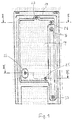
- FIG. 1 shows a top view of a housing wall a housing of a heater
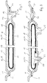
- Figure 2 shows a cross section through the housing wall along the line II-II in Figure 1
- FIG. 3 shows a cross section through the housing wall the line III-III in Figure 3.
- Figure 1 shows a rear wall 10 of a not shown Housing of a heater.
- On the rear wall 10 is one shell-shaped wall 14 attached so that between the rear wall 10 and the bowl-shaped wall 14 a at least partially across the width and height of the back wall 10 approximately rectangular cavity 16 is formed.
- the wall 14 points into the interior of the housing.
- the back wall 10 and the wall 14 are each as deep-drawn or embossed Sheet metal parts executed. For stiffening the sheet metal part depressions or beads 11 are embossed on the rear wall 10 or deep-drawn. The introduction of further beads in the Sheet metal parts of the rear wall 10 and / or the wall 14 are equally possible. These beads serve to stiffen the Outer wall of the expansion vessel 20 forming bleaching parts.
- a bubble elastic membrane 18 Inside the cavity 16 is a bubble elastic membrane 18.
- the cavity 16 forms with the membrane 18 an expansion vessel 20 for a not shown hydraulic pipe system of the heater.
- the Membrane 18 is connected, for example, via a filling connection 22 and a filling valve, not shown, filled with nitrogen.
- the wall 14 has a first connection 23 for a vent valve, a second connection 24 for a safety valve and a third connection 25 for the line network of the heating water, for example in the sheet metal part the wall 14 are molded.
- the connections 23, 24, 25 can be designed as threaded and / or plug connections his.
- the wall 14 according to FIG. 3 has an opening 27 which is dimensioned such that the membrane 18th is exchangeable through this opening.
- the attachment the membrane 18 on the wall 14 takes place in a manner known per se Way by means of a flange 29 which the membrane 18th is tightly clamped between itself and the wall 14.
- the flange 29 takes the already mentioned inlet opening 22 with the Inlet valve, not shown.
- the wall 14 is hydraulically tight on the rear wall 10, connected for example by means of a circumferential weld seam 31. But it is also conceivable to use a screw or To provide riveted connection between rear wall 10 and wall 14, but then a circumferential seal between the both sheet metal parts must be present.
- connection 24 for the safety valve on the side next to arranged in the cavity 16 with the cavity 16 and connection 24 is a connecting channel 33, which in the Wall 14 is stamped or molded.
- Drain channel 35 with an upper connection 36 and a lower one Connection 37 formed.
- the drain channel 36 is in the wall 14 also by deep drawing or stamping brought in.
- the connections 36, 37 are the same as the connections 23, 24, 25 formed in the sheet metal part of the wall 14.
- the drain channel 35 serves to discharge the from the safety valve or pressure relief valve flowing out of heating water, that in the upper connection via a not shown Connection is routed and at the foot of the rear wall 10 in drainage can flow
Landscapes
- Engineering & Computer Science (AREA)
- Physics & Mathematics (AREA)
- Thermal Sciences (AREA)
- Chemical & Material Sciences (AREA)
- Combustion & Propulsion (AREA)
- Mechanical Engineering (AREA)
- General Engineering & Computer Science (AREA)
- Instantaneous Water Boilers, Portable Hot-Water Supply Apparatuses, And Control Of Portable Hot-Water Supply Apparatuses (AREA)
- Filling Or Discharging Of Gas Storage Vessels (AREA)
- Housings, Intake/Discharge, And Installation Of Fluid Heaters (AREA)
Abstract
Description
Claims (6)
- Heizgerät mit einem Gehäuse, in dem ein an ein Leitungsnetz angeschlossener Wärmetauscher untergebracht ist, und mit einem Ausdehnungsgefäß, welches ebenfalls mit dem Leitungsnetz in Verbindung steht, dadurch gekennzeichnet, dass das Ausdehnungsgefäß (20) mindestens zwei schalenförmige Teile aufweist und dass mindestens ein schalenförmiges Teil von einer Wand (10) des Gehäuses gebildet ist.
- Heizgerät nach Anspruch 1, dadurch gekennzeichnet, dass das eine schalenförmige Teil des Ausdehnungsgefäßes (20) von der Rückwand des Gehäuses gebildet ist.
- Heizgerät nach Anspruch 1, dadurch gekennzeichnet, dass das andere schalenförmige Teil von einer in das Innere des Gehäuses weisenden Wandung (14) gebildet ist.
- Heizgerät nach Anspruch 4, dadurch gekennzeichnet, dass an die Wandung (14) Anschlüsse (23, 24, 25) für das Leitungsnetz und/oder Ventile angeformt sind.
- Heizgerät nach Anspruch 1, dadurch gekennzeichnet, dass zumindest in ein schalenförmiges Teil (10, 14) einen Ablaufkanal (35) zum Ableiten des aus einem Überdruckventil bzw. Sicherheitsventil ausströmenden Heizwassers eingeformt ist.
- Heizgerät nach Anspruch 1, dadurch gekennzeichnet, dass zumindest eines der schalenförmigen Teile (10, 14) aus einem Blechteil besteht.
Applications Claiming Priority (2)
| Application Number | Priority Date | Filing Date | Title |
|---|---|---|---|
| DE2000154032 DE10054032A1 (de) | 2000-10-31 | 2000-10-31 | Heizgerät mit integriertem Ausdehnungsgefäß |
| DE10054032 | 2000-10-31 |
Publications (2)
| Publication Number | Publication Date |
|---|---|
| EP1202000A2 true EP1202000A2 (de) | 2002-05-02 |
| EP1202000A3 EP1202000A3 (de) | 2003-05-07 |
Family
ID=7661720
Family Applications (1)
| Application Number | Title | Priority Date | Filing Date |
|---|---|---|---|
| EP01123017A Ceased EP1202000A3 (de) | 2000-10-31 | 2001-09-26 | Heizgerät mit integriertem Ausdehnungsgefäss |
Country Status (2)
| Country | Link |
|---|---|
| EP (1) | EP1202000A3 (de) |
| DE (1) | DE10054032A1 (de) |
Cited By (4)
| Publication number | Priority date | Publication date | Assignee | Title |
|---|---|---|---|---|
| WO2006070282A3 (en) * | 2004-12-28 | 2006-10-19 | Renato Vaiani | Integrated hydraulic unit |
| FR2884970A1 (fr) * | 2005-04-26 | 2006-10-27 | Renault Sas | Vase d'expansion et de degazage pour circuit de liquide de refroidissement, et procede associe |
| ITAN20120125A1 (it) * | 2012-10-03 | 2014-04-04 | Ariston Thermo Spa | Vaso di espansione per apparecchi termosanitari |
| CN110425743A (zh) * | 2019-07-25 | 2019-11-08 | 广东万家乐燃气具有限公司 | 一种带膨胀气箱的燃气热水设备 |
Families Citing this family (3)
| Publication number | Priority date | Publication date | Assignee | Title |
|---|---|---|---|---|
| DE102004027211B4 (de) * | 2004-06-03 | 2006-06-29 | Robert Bosch Gmbh | Heizgerät mit integriertem Ausdehnungsgefäß |
| EP2616733A1 (de) | 2010-09-17 | 2013-07-24 | Voith Patent GmbH | Ölsystem zur schmierölversorgung einer arbeits- und/oder antriebsmaschine |
| DE102020110609A1 (de) | 2020-04-20 | 2021-10-21 | Audi Aktiengesellschaft | Brennstoffzellenvorrichtung mit einem Kühlmittelrohr sowie ein Kraftfahrzeug mit einer solchen Brennstoffzellenvorrichtung |
Citations (1)
| Publication number | Priority date | Publication date | Assignee | Title |
|---|---|---|---|---|
| DE9417715U1 (de) | 1993-11-08 | 1994-12-15 | Joh. Vaillant Gmbh U. Co, 42859 Remscheid | Heizgerät |
Family Cites Families (6)
| Publication number | Priority date | Publication date | Assignee | Title |
|---|---|---|---|---|
| FR1346034A (fr) * | 1959-04-11 | 1963-12-13 | Chauffage central à eau chaude avec chauffe-eau à gaz | |
| DE1959692U (de) * | 1966-02-19 | 1967-05-03 | Brumme Kg Effbe Werk | Vorrichtung fuer geschlossene hydraulische anlagen zur druckausdehnung. |
| DE1579933C3 (de) * | 1966-11-25 | 1978-07-13 | Robert Bosch Gmbh, 7000 Stuttgart | Gasbeheizter Umlauf-Wassererhitzer für eine geschlossene Sammelheizungsanlage |
| CH577665A5 (de) * | 1973-07-11 | 1976-07-15 | Fascione Pietro | |
| DE4135439A1 (de) * | 1990-11-08 | 1992-06-04 | Artec Design Gmbh | Gasdurchlauferhitzer |
| DE9017471U1 (de) * | 1990-12-24 | 1991-03-14 | Gratz, Erich, O-6081 Rotterode | Fahrbares Reinigungsgerät |
-
2000
- 2000-10-31 DE DE2000154032 patent/DE10054032A1/de not_active Withdrawn
-
2001
- 2001-09-26 EP EP01123017A patent/EP1202000A3/de not_active Ceased
Patent Citations (1)
| Publication number | Priority date | Publication date | Assignee | Title |
|---|---|---|---|---|
| DE9417715U1 (de) | 1993-11-08 | 1994-12-15 | Joh. Vaillant Gmbh U. Co, 42859 Remscheid | Heizgerät |
Cited By (4)
| Publication number | Priority date | Publication date | Assignee | Title |
|---|---|---|---|---|
| WO2006070282A3 (en) * | 2004-12-28 | 2006-10-19 | Renato Vaiani | Integrated hydraulic unit |
| FR2884970A1 (fr) * | 2005-04-26 | 2006-10-27 | Renault Sas | Vase d'expansion et de degazage pour circuit de liquide de refroidissement, et procede associe |
| ITAN20120125A1 (it) * | 2012-10-03 | 2014-04-04 | Ariston Thermo Spa | Vaso di espansione per apparecchi termosanitari |
| CN110425743A (zh) * | 2019-07-25 | 2019-11-08 | 广东万家乐燃气具有限公司 | 一种带膨胀气箱的燃气热水设备 |
Also Published As
| Publication number | Publication date |
|---|---|
| EP1202000A3 (de) | 2003-05-07 |
| DE10054032A1 (de) | 2002-05-08 |
Similar Documents
| Publication | Publication Date | Title |
|---|---|---|
| DE202009001056U1 (de) | Heizkreisverteiler | |
| EP1202000A2 (de) | Heizgerät mit integriertem Ausdehnungsgefäss | |
| DE3527700A1 (de) | Betriebsmittelbehaelter in kraftfahrzeugen | |
| EP1881288A1 (de) | Rohr-Rippen-Block-Wärmetauscher mit Verbindungs- bzw. Anschlussblöcken | |
| DE3204381C2 (de) | Heizkörper für eine Heiz- oder Klimaanlage eines Kraftfahrzeuges und Verfahren zu dessen Herstellung | |
| AT411294B (de) | Heiz-(kühl-)körper | |
| DE102005062660B4 (de) | Warmwasserbereiter sowie Grundbehälter für einen Warmwasserbereiter | |
| AT411493B (de) | Paneelheizkörper sowie stützteil hiefür | |
| EP0595945B1 (de) | Doppelwandiger heizschacht | |
| EP1036993A2 (de) | Kaskaden-Heizungsanlage mit zwei oder mehr Heizkesseln | |
| CH693966A5 (de) | Heizkoerper und Anschlussgarnitur. | |
| DE29719311U1 (de) | Wärmetauscher | |
| DE102007025823B4 (de) | Einbauventil, insbesondere für einen Gliederheizkörper, und Gliederheizkörper | |
| DE10223790B4 (de) | Plattenheizkörper | |
| DE102008026074B3 (de) | Wärmetauscher | |
| DE10300119B4 (de) | Kondensatableiter | |
| AT411293B (de) | Heiz-(kühl-)körper | |
| DE3535340C2 (de) | ||
| AT409545B (de) | Heiz-(kühl-)körper | |
| DE19727145A1 (de) | Gehäuseloser Plattenwärmetauscher | |
| DE3142632C1 (de) | Gasheizkessel | |
| EP0563589A1 (de) | Heizkessel | |
| DE29822781U1 (de) | Einrichtung für eine Heizungsanlage, mit einer hydraulischen Weiche und mit einem Heizkreisverteiler | |
| AT408272B (de) | Verteilergruppe zum anschliessen eines plattenheizkörpers an die rohrleitungen einer heizungsanlage | |
| DE29801958U1 (de) | Heizkörper mit integrierter Ventilgarnitur für Mittenanschluß |
Legal Events
| Date | Code | Title | Description |
|---|---|---|---|
| PUAI | Public reference made under article 153(3) epc to a published international application that has entered the european phase |
Free format text: ORIGINAL CODE: 0009012 |
|
| AK | Designated contracting states |
Kind code of ref document: A2 Designated state(s): AT BE CH CY DE DK ES FI FR GB GR IE IT LI LU MC NL PT SE TR |
|
| AX | Request for extension of the european patent |
Free format text: AL;LT;LV;MK;RO;SI |
|
| RIN1 | Information on inventor provided before grant (corrected) |
Inventor name: PORZER, VOLKER Inventor name: OEHRLEIN, MANFRED Inventor name: DEBOWSKI, DOBROMIL Inventor name: KROELL, ULRICH |
|
| PUAL | Search report despatched |
Free format text: ORIGINAL CODE: 0009013 |
|
| AK | Designated contracting states |
Designated state(s): AT BE CH CY DE DK ES FI FR GB GR IE IT LI LU MC NL PT SE TR |
|
| AX | Request for extension of the european patent |
Extension state: AL LT LV MK RO SI |
|
| 17P | Request for examination filed |
Effective date: 20031107 |
|
| AKX | Designation fees paid |
Designated state(s): DE ES FR GB IT NL |
|
| 17Q | First examination report despatched |
Effective date: 20040224 |
|
| STAA | Information on the status of an ep patent application or granted ep patent |
Free format text: STATUS: THE APPLICATION HAS BEEN REFUSED |
|
| 18R | Application refused |
Effective date: 20071231 |