EP1199953B1 - Reinigungsvorrichtung für einen rasierapparat - Google Patents
Reinigungsvorrichtung für einen rasierapparat Download PDFInfo
- Publication number
- EP1199953B1 EP1199953B1 EP00951462A EP00951462A EP1199953B1 EP 1199953 B1 EP1199953 B1 EP 1199953B1 EP 00951462 A EP00951462 A EP 00951462A EP 00951462 A EP00951462 A EP 00951462A EP 1199953 B1 EP1199953 B1 EP 1199953B1
- Authority
- EP
- European Patent Office
- Prior art keywords
- cleaning
- cleaning liquid
- cleaning device
- liquid container
- conduit
- Prior art date
- Legal status (The legal status is an assumption and is not a legal conclusion. Google has not performed a legal analysis and makes no representation as to the accuracy of the status listed.)
- Expired - Lifetime
Links
- 238000004140 cleaning Methods 0.000 title claims abstract description 227
- 239000007788 liquid Substances 0.000 claims abstract description 104
- 238000007789 sealing Methods 0.000 claims abstract description 43
- 239000000356 contaminant Substances 0.000 claims abstract description 3
- 230000005484 gravity Effects 0.000 claims description 6
- 239000012530 fluid Substances 0.000 description 24
- 238000005520 cutting process Methods 0.000 description 10
- 230000009471 action Effects 0.000 description 6
- 230000008901 benefit Effects 0.000 description 6
- 238000001704 evaporation Methods 0.000 description 5
- 230000008020 evaporation Effects 0.000 description 5
- 239000012528 membrane Substances 0.000 description 4
- 230000008878 coupling Effects 0.000 description 3
- 238000010168 coupling process Methods 0.000 description 3
- 238000005859 coupling reaction Methods 0.000 description 3
- 238000006073 displacement reaction Methods 0.000 description 3
- 238000000034 method Methods 0.000 description 3
- 230000008569 process Effects 0.000 description 3
- 239000012535 impurity Substances 0.000 description 2
- 238000009434 installation Methods 0.000 description 2
- 238000001035 drying Methods 0.000 description 1
- 230000000694 effects Effects 0.000 description 1
- 239000013013 elastic material Substances 0.000 description 1
- 238000004519 manufacturing process Methods 0.000 description 1
- 230000009467 reduction Effects 0.000 description 1
- 238000010992 reflux Methods 0.000 description 1
- 238000000926 separation method Methods 0.000 description 1
- 210000000352 storage cell Anatomy 0.000 description 1
Images


Classifications
-
- A—HUMAN NECESSITIES
- A45—HAND OR TRAVELLING ARTICLES
- A45D—HAIRDRESSING OR SHAVING EQUIPMENT; EQUIPMENT FOR COSMETICS OR COSMETIC TREATMENTS, e.g. FOR MANICURING OR PEDICURING
- A45D27/00—Shaving accessories
- A45D27/46—Devices specially adapted for cleaning or disinfecting shavers or razors
Definitions
- the invention relates to a cleaning device in the preamble of claim 1 specified type.
- a cleaning device of the type mentioned is known from WO 98/35581 A.
- the invention is based on the object, a cleaning device of the above to improve the type mentioned, in particular the evaporation of cleaning fluid to reduce the cleaning liquid container.
- the cleaning device according to the present invention has several advantages.
- One An essential advantage of the invention is that in the coupling state of the cleaning liquid container with the cleaning tub required for the liquid circulation Inlet opening and outlet opening of the cleaning liquid container of sealing elements is surrounded, so that only the circulation of the cleaning fluid with or No impurities required opening cross-section for the escape of evaporated Cleaning fluid in the drain line remains.
- the flow cross section of the drain line is dimensioned according to the invention such that the cleaning liquid including Drain contaminants in the cleaning liquid container and that through this inlet liquid to be displaced from the gas-tight cleaning liquid container gaseous volume can escape from the cleaning liquid container.
- the flow cross section The drain line can be relatively secure while ensuring these conditions be sized small, so that in the non-use state of the cleaning device occurring evaporation loss of cleaning fluid can be reduced to a minimum can.
- a preferred embodiment of the invention is characterized in that the drain line a pressure equalization line is assigned.
- the drain line is a pressure equalization line as an integral part of the drain line assigned.
- the pressure equalization line is formed by a pipeline. This measure ensures a separation of incoming cleaning liquid with simultaneous outflow of displaced gaseous medium, consequently a safe drain of the cleaning liquid from the Cleaning tub and an unhindered outflow of gaseous volume from the Interior of the cleaning liquid container, by the inflow of cleaning liquid is made in the container contracted.
- Another embodiment of the invention is characterized in that one in the cleaning tub provided overflow wall protrudes into the drain line. Which through the Overflow wall in the drain line resulting second flow channel favors both the Reflux before cleaning fluid in the cleaning tank as well as the consequent Displacement of gaseous volumes from the cleaning fluid reservoir.
- a further advantageous embodiment of the invention is characterized in that the Flow cross section of the drain line by means of the pressure equalization line and the overflow wall can be divided into three flow channels, so that each of the flow channels one certain function can be assigned to.
- a very simple and inexpensive embodiment of the invention is characterized from that on the outer wall of the drain line at an inlet opening of the cleaning liquid container can be applied applyable sealing element.
- the invention provided that the flow cross-section of the drain line by means of at least a valve element is variable. Starting from a flow cross-section covering valve element is depending on the design of the valve element of the flow cross-section the drain line through the valve element more or less reduced become.
- valve element under the action of running cleaning liquid the flow cross-section of the drain line essentially releases.
- the arrangement and design of the valve element may be made according to an embodiment of the invention such that the valve element under the action of a gaseous overpressure occurring in the cleaning liquid container at least a portion of the flow area of the drain line and / or the pressure equalization line releases.
- a further advantageous embodiment of the invention is characterized in that the drain line and / or at the pressure equalization line a stop for the installation of the valve element is provided to preferably a complete coverage of the respective or the respective To achieve flow cross sections.
- At pressure equalization between Drain line and the interior of the cleaning liquid container of the flow cross-section is at least partially covered by the valve element. This measure ensures safe in certain embodiments of the invention Drain of cleaning fluid into the cleaning fluid reservoir and outflow of accordingly displaceable gas volume from the interior of the cleaning liquid container.
- the effective valve area of the valve element is effective formed smaller than the flow cross-section.
- the Valve element is designed as a controllable by gravity flap valve. through This measure can be the flow cross-section of the drain line and / or the pressure equalization line without affecting effective drainage of cleaning fluid from the cleaning liquid container and the required outflow of a gaseous medium from the interior of the cleaning liquid container effectively be sealed by the valve element for those time intervals between the respective uses of the cleaning device with a corresponding device of personal needs, such as a razor.
- valve element is formed of an elastic membrane.
- the valve element provided on the sealing element is the valve element on the drain line intended.
- a valve element of the drain line and a valve element attributable to the pressure equalization line are according to one embodiment the invention of advantage, a valve element of the drain line and a valve element attributable to the pressure equalization line.
- the drain line extant sealing element protrudes into the cleaning liquid container and in a relatively short distance to a maximum filling level of the cleaning liquid ends.
- the Pressure equalization line protrudes into the cleaning liquid container and in a relative small distance to a maximum filling level of the cleaning liquid ends.
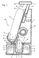
- Fig. 1 shows a cross section through a cleaning device RV for cleaning a Cutting head S of a razor R with a housing 1, a holding device 2, a cleaning liquid container 3, a filter element 4, one of a motor 5 drivable Conveyor 6 with a supply line 7 to a cleaning tub 8 and a drain line 9 from the cleaning tub 8 to the cleaning liquid container 3.
- Der Cleaning liquid container 3 is provided with an integrated filter element 4 below the cleaning trough 8 and arranged above a wall 12 of the housing 1.
- the conveyor 6 is out of the interior 10 of the cleaning liquid container RV and indeed from the filter housing 40 removably arranged. Between the filter housing 40 and the pump housing 50, a sealing element 51 is arranged to a flow of cleaning fluid 11 to prevent from the cleaning liquid container 3.
- the inner curvature of the cleaning trough 8 is approximately the outer contour of the to be cleaned Object, such. B. the outer contour of a cutting head S of a shaver R customized.
- the cleaning tub 8 receives only as much cleaning liquid 11, as for the respective cleaning process is required.
- the cleaning tub 3 has an overflow device 17, so that the cleaning liquid 11 in the cleaning tub a certain Level does not exceed.
- the overflow device 17 ensures that through the cutting head S or a part of the cutting head S during operation of the cleaning device RV of cleaning liquid 11 is surrounded and prevents overflow of cleaning fluid 11 over the edge of the cleaning tub 8.
- the flow of the cleaning liquid 11 of the Cleaning tub 8 to the cleaning liquid container 3 is in this embodiment ensured by the outlet opening 18 in the drain line 9 in the tub bottom 19 of the Cleaning tub 8, on the outflow cross section, the level of cleaning fluid in the cleaning tub is also controllable, and one, for example, designed as a funnel Inlet opening 15 in the cleaning liquid container 3.
- the inlet opening 15 and the outlet opening 30 in the cleaning liquid container 3 are for the purpose of transport the replaceable cleaning liquid container 3, for example by means of a closure - not shown - lockable.
- the shaver R is by means of an adjustable arranged holding device 2 in the Cleaning tub 8 held.
- the holding device 2 is essentially parallel to a broad side of the shaver R extending wall 23 and one of the bottom wall the razor R associated wall 22 formed.
- On the wall 22 is a as Appliance plug formed retaining element 24 is provided.
- the coupled with the wall 22 Wall 23 of the holding device 2 is in the housing 1, for example, parallel to the housing broadside of the shaver R slidably mounted, such that a shift in the Holding device 2 in the direction of cleaning tank 8 a coupling of the device plug trained holding member 24 with the appliance socket 28 of the shaver R and at a displacement of the holding device 2 in the opposite direction decoupling the holding device 2 is ensured by the shaver R.
- the coupling of the Appliance plug of the retaining element 24 with the device socket 28 ensures over the Connection to the in the cleaning device RV for the commissioning of the conveyor 6 and / or fan 29 electrical circuit provided a supply of a electrical voltage for various purposes, such as. B.
- a fan 29 with an air supply for drying the For example, illustrated cutting head S after completion of cleaning, d. H. after completed Drain of the cleaning liquid 11 provided from the cleaning tub 8.
- the Connection and disconnection of the fan 29 may be part of a switching program of a programmable Switching device - not shown - and / or separately controlled by hand be.
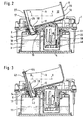
- Fig. 2 shows a side view of the cleaning device RV with a longitudinal section through the chassis 20 of the housing 1, i. a higher cleaning fluid on one in the chassis 20 arranged cleaning liquid container 3 and one inclined on the chassis 20 arranged to a horizontal plane cleaning tub 8.
- the inclination angle the cleaning tub 8 and the tub bottom 31 of the cleaning tub 8 for horizontal Level H causes a rapid drainage of the cleaning liquid, i. leads to a higher flow rate.
- the section through the cleaning tub 8 makes clearly that in addition to the sloping trough bottom 19, the two end walls 25, 26 of the cleaning tub 8 also inclined to the horizontal plane H, so that a drainage of cleaning liquid 11 from these end walls 25, 26 of the cleaning tub 8 is also guaranteed.
- the drain line 9 is surrounded by a sealing element 14 which on the lower end of Drain line 9 is pushed and held by a residual stress.
- the cleaning tub 8 is in vertical together with the chassis 20 in the cleaning device RV Direction arranged back and forth.
- the arrangement of the cleaning fluid container 3 in the chassis 20 of the housing 1 is made such that at a merge the cleaning tub 8 and the cleaning liquid container 3, the drain line. 9 with the sealing element 14 through the inlet opening 15 in the interior 10 of the cleaning liquid container 3 is introduced until the sealing element 14 on the edge of the inlet opening 15 comes sealingly to the plant.
- this merged state of cleaning tub 8 and cleaning liquid container 3 is the interior 10 of the cleaning liquid container 3 only over the flow cross-section of the drain line 9 with the external environment of the cleaning device RV connected.
- the flow cross section the drain line 9 is dimensioned such that during use of the cleaning device RV cleaning fluid both on the intended outlet port 18 as well over the overflow wall 25 in the interior 10 of the cleaning liquid container 3 unhindered drain and the existing in the interior gaseous medium, which correspond This supply of cleaning fluid is displaced via the drain line 9 unhindered can flow out.
- the flow cross section of Drain line 9 are dimensioned relatively small, so that in the non-use state of the cleaning device RV the loss of cleaning fluid due to evaporation is relatively low is.
- Fig. 3 shows a longitudinal section through the lower part of a cleaning device RV according to Fig. 2 with a drain line 9 associated pressure equalization line 43.
- Die Pressure equalization line 43 for example, directly on the outer wall of the drain line 9 or as an integral part of the drain line 9 in the flow cross-section be provided.
- a significant advantage of these alternative embodiments is that the sealing element 14 for sealing the drain line 9 and the Pressure equalization line 43 can be used.
- the pressure equalization line 43 is provided separately from the drain line 9 is, the pressure equalization line with an additional sealing element - not shown - seal.
- the pressure equalization line 43 is part of the drain line 9 and thus integrated in the flow cross-section.
- the pressure compensation line 43 is therefore via the lower end of the drain line 9, that of a sealing element 14th is surrounded with respect to the cleaning liquid container 3 with sealed.
- the flow cross section the drain line 9 is in the region of the outlet opening 18 of the cleaning tub 8 through the overflow wall 25 and through the wall of the pipe formed
- Pressure equalization line 43 divided into three separate flow channels, so, that over the outlet opening 18 and over the overflow wall 25 cleaning fluid 11 unhindered drain into the interior 10 of the cleaning liquid container 3 and from there according to the displacement principle gaseous medium via the pressure equalization line 43 in the atmosphere can flow out.
- a valve element 42 is provided, by means of which a part of the flow cross-section the drain line 9 of the adjoining the outlet port 18 Channel and the overflow wall 25 formed channel is composed, lockable is.
- the claimed by the pressure equalization line 43 cross-sectional area of Flow cross-section of the drain line 9 is at the in the interior of the cleaning liquid container protruding end formed open while at the opposite end End of the pressure equalization line 43 a the flow cross-section of the pressure equalization line 43 closing valve element 44 is provided.
- the valve element 42 can be formed as an elastic membrane and either on the drain line 9 or as in Fig. 3, to be formed on the sealing element 14.
- the Anformung can be made in this way be that the valve element without additional spring but only because of his elastic properties under the action of effluent from the cleaning tank 8 Cleaning liquid 11 is opened and after completion of this process automatically springs back into its closed position.
- An analogous training can for the at the pressure equalization line 43 provided valve element 44 may be provided.
- the valve element 44 may for example consist of an elastic ring element which can be pushed onto a pipeline be formed with a molded elastic membrane.
- valve elements 42 and 44 The function of the valve elements 42 and 44 is in the embodiment of FIG. 3 such taken that caused by flowing out of the cleaning tub cleaning fluid 11 initially the valve member 42 opens and displaced under the action of the outflow gaseous medium, the valve element 44 opens and that after completion of the outflow of cleaning fluid 11 from the cleaning tub 8, both the valve element 42nd as well as the valve element 44, the respective flow cross section of the drain line 9 and the pressure equalization line 43 closes, so that in the now given non-use state the cleaning device RV the interior 10 of the cleaning liquid container 3 is closed to the atmosphere.
- Fig. 4 shows a longitudinal section through a part of the lower part of a cleaning device RV with a representation of between the drain line 9 of the cleaning tub 8 and the inlet opening 15 of the cleaning liquid container 3 provided sealing element 14, according to the embodiment of FIG. 2.
- the drain line 9 protrudes with the drain line 9 extending sealing element 14 in the interior 10 of the cleaning liquid container 3 in, wherein the distance of the lower end of the sealing element 14 to the liquid level 48 the cleaning liquid 11 in a still unused state - manufacturing state - occupies.
- This measure leads to a reduction of the loss Cleaning liquid 11 assuming that in the non-use state of the cleaning device the flow cross-section of the drain line or the sealing element 14 is not complete but completely open or only partially released by a valve element.
- valve element 42 is for example as a flexible membrane on the sealing element 14 formed and closes a part of both for the supply of cleaning fluid 11 as well as for the outflow of a part of the cleaning liquid container existing gaseous Vorlumens is required, from.
- Fig. 5 shows a section through the chassis 20 and through the cleaning liquid container 3 of the cleaning device RV of FIG. 4 in a perspective view with a view from the lower end of a in a filter housing 40, conveyor 6 and on the inlet opening 15 of the cleaning liquid container 3 for the return of cleaning liquid in the interior 10 of the cleaning liquid container 3.
- a valve element 42 is formed, for example, the half of the flow cross-section the drain line 9 and the sealing element 14 covers.
- Fig. 6 shows an embodiment of a drain line 9 with a pushed-sealing element 14, in which a gravity-controlled flap valve is provided.
- the sealing element 14 stops 45 and 46 are provided, on which the valve elements 42 and 44 of the flapper valve 54 in the non-use state of the cleaning device RV with gravity control to the system reach the stops 45 and 46.
- the Valve elements 42 and 44 are in the flow cross section of the drain line 9 and the sealing element 14 inclined to a horizontal plane H pivotable and eime pivot axis 56, wherein a tilted to a vertical direction V arranged weight 55th the gravity control of the valve elements 42 and 44 causes.
- the arrangement of the stops 45 and 46 on the sealing element 14 is made such that under the action of the Cleaning tub draining cleaning fluid 11, the valve member 42 to the Pivot axis 56 of the stop 46 away in the interior 10 of the cleaning liquid container pivots while caused by the in the cleaning liquid container constructive overpressure the valve member 44 also about the pivot axis 56 of the stop 45 away in the flow channel of the sealing element 14 and the drain line 9 pivots in to let the gaseous medium to flow into the atmosphere.
Landscapes
- Dry Shavers And Clippers (AREA)
- Cleaning By Liquid Or Steam (AREA)
- Cleaning In General (AREA)
Description
- Fig. 1
- einen Querschnitt durch eine Reinigungsvorrichtung mit einem unterhalb der Reinigungswanne vorgesehenen Reinigungsflüssigkeitbehälter mit integriertem Filter, ei-. ner Fördereinrichtung, einer Zuleitung zur Reinigungswanne, in der ein Schneidkopf eines Rasierapparates gelagert ist sowie eine Ablaufleitung,
- Fig. 2
- einen Längsschnitt durch den unteren Teil einer Reinigungsvorrichtung insbesondere durch eine Reinigungswanne sowie einen Reinigungsflüssigkeitsbehälter mit Dichtelementen zur Abdichtung einer Einlaßöffnung und einer Auslaßöffnung des Reinigungsflüssigkeitsbehälters,
- Fig. 3
- einen Längsschnitt durch den unteren Teil einer Reinigungsvorrichtung gemäß Fig. 2 mit einer der Ablaufleitung zugeordneten Druckausgleichsleitung,
- Fig. 4
- einen Längsschnitt durch einen Teil des unteren Teils einer Reinigungsvorrichtung mit einer vergrößerten Darstellung des zwischen der Ablaufleitung der Reinigungswanne und der Einlaßöffnung des Reinigungsflüssigkeitsbehälters vorgesehenen Dichtelementes,
- Fig. 5
- einen Schnitt durch das Chassis sowie durch den Reinigungsflüssigkeitsbehälter der Reinigungsvorrichtung in einer perspektivischen Darstellung mit einer Sicht auf das untere Ende einer in einem Filtergehäuse vorgesehenen Fördereinrichtung sowie auf die Einlaßöffnung für die Rückführung von Reinigungsflüssigkeit in den Reinigungsflüssigkeitsbehälter,
- Fig. 6
- eine Ausführungsform einer Ablaufleitung mit einem aufgeschobenen Dichtelement sowie einem schwerkraftgeregelten Klappenventil.
Claims (21)
- Reinigungsvorrichtung (RV) mit einem Gehäuse (1) und mit einer Reinigungswanne (8) zur Aufnahme eines Gerätes des persönlichen Bedarfs, insbesondere eines Schneidkopfes (S) eines Rasierapparates (R), einem austauschbar angeordneten Reinigungsflüssigkeitsbehälter (3) mit einer Einlaßöffnung (15) und einer Auslaßöffnung (18), einem Dichtelement (51) zur Abdichtung der Auslaßöffnung (18), einer von einem Motor (5) antreibbaren Fördereinrichtung (6) zur Förderung einer Reinigungsflüssigkeit (11) aus dem Reinigungsflüssigkeitsbehälter (3) in die Reinigungswanne (8), deren Ablaufleitung (9) mit einer Einlaßöffnung (15) des Reinigungsflüssigkeitsbehälters (3) koppelbar ist, dadurch gekennzeichnet, daß zwischen der Ablaufleitung (9) und der Einlaßöffnung (15) ein Dichtelement (14) vorgesehen ist und daß der Strömungsquerschnitt der Ablaufleitung (9) derart bemessen ist, daß die Reinigungsflüssigkeit (11) einschließlich Verunreinigungen in den Reinigungsflüssigkeitsbehälter (3) ablaufen sowie gasförmiges Medium aus dem Reinigungsflüssigkeitsbehälter (3) austreten kann.
- Reinigungsvorrichtung nach Anspruch 1, dadurch gekennzeichnet, daß der Ablaufleitung (9) eine Druckausgleichsleitung (43) zugeordnet ist.
- Reinigungsvorrichtung nach Anspruch 1 oder 2, dadurch gekennzeichnet, daß der Ablaufleitung (9) eine Druckausgleichsleitung (43) als integraler Bestandteil der Ablaufleitung (9) zugeordnet ist.
- Reinigungsvorrichtung nach einem der Ansprüche 1 bis 3, dadurch gekennzeichnet, daß die Druckausgleichsleitung (43) durch eine Rohrleitung gebildet ist.
- Reinigungsvorrichtung nach einem der vorhergehenden Ansprüche, dadurch gekennzeichnet, daß eine in der Reinigungswanne (8) vorgesehene Überlaufwand (25) in die Ablaufleitung (9) hineinragt.
- Reinigungsvorrichtung nach einem der vorhergehenden Ansprüche, dadurch gekennzeichnet, daß der Strömungsquerschnitt der Ablaufleitung (9) mittels der Druckausgleichsleitung (43) und der Überlaufwand (25) in drei Strömungskanäle aufteilbar ist.
- Reinigungsvorrichtung nach einem der vorhergehenden Ansprüche, dadurch gekennzeichnet, daß an der Außenwandung der Ablaufleitung (9) ein an einer Einlaßöffnung (15) des Reinigungsflüssigkeitsbehälters (3) anlegbares Dichtelement (14) vorgesehen ist.
- Reinigungsvorrichtung nach einem der vorhergehenden Ansprüche, dadurch gekennzeichnet, daß der Strömungsquerschnitt der Ablaufleitung (9) mittels wenigstens eines Ventilelementes (42, 44) veränderbar ist.
- Reinigungsvorrichtung nach einem der vorhergehenden Ansprüche, dadurch gekennzeichnet, daß das Ventilelement (42,44) unter Einwirkung von ablaufender Reinigungsflüssigkeit (11) den Strömungsquerschnitt der Ablaufleitung (9) im wesentlichen freigibt.
- Reinigungsvorrichtung nach einem der vorhergehenden Ansprüche, dadurch gekennzeichnet, daß das Ventilement (42, 44) unter Einwirkung eines im Reinigungsflüssigkeitsbehälter (3) auftretenden gasförmigen Überdruckes wenigstens einen Teilbereich des Strömungsquerschnittes der Ablaufleitung (9) freigibt.
- Reinigungsvorrichtung nach einem der vorhergehenden Ansprüche, dadurch gekennzeichnet, daß an der Ablaufleitung (9) und/oder Druckausgleichsleitung (43) ein Anschlag (45, 46) zur Anlage des Ventilelementes (42, 43) vorgesehen ist.
- Reinigungsvorrichtung nach einem der vorhergehenden Ansprüche, dadurch gekennzeichnet, daß bei Druckausgleich zwischen Ablaufleitung (9) und dem Innenraum (10) des Reinigungsflüssigkeitsbehälters (3) der Strömungsquerschnitt durch das Ventilelement (42, 44) wenigstens teilweise abdeckbar ist.
- Reinigungsvorrichtung nach einem der vorhergehenden Ansprüche, dadurch gekennzeichnet, daß die wirksam werdende Ventilfläche des Ventilelementes (42, 44) kleiner als der Strömungsquerschnitt ausgebildet ist.
- Reinigungsvorrichtung nach einem der vorhergehenden Ansprüche, dadurch gekennzeichnet, daß das Ventilelement (42, 44) als durch Schwerkraft regelbares Klappenventil (54) ausgebildet ist.
- Reinigungsvorrichtung nach einem der vorhergehenden Ansprüche, dadurch gekennzeichnet, daß das Ventilelement (42, 44) aus einer elastischen Membrane gebildet ist.
- Reinigungsvorrichtung nach einem der vorhergehenden Ansprüche, dadurch gekennzeichnet, daß das Ventilelement (42, 44) an dem Dichtelement (14) vorgesehen ist.
- Reinigungsvorrichtung nach einem der vorhergehenden Ansprüche, dadurch gekennzeichnet, daß das Ventilelement (42, 44) an der Ablaufleitung (9) vorgesehen ist.
- Reinigungsvorrichtung nach einem der vorhergehenden Ansprüche, dadurch gekennzeichnet, daß ein Ventilelement (42) der Ablaufleitung (9) und ein Ventilelement (44) der Druckausgleichsleitung zugeordnet ist.
- Reinigungsvorrichtung nach einem der vorhergehenden Ansprüche, dadurch gekennzeichnet, daß die Ablaufleitung (9) in den Reinigungsflüssigkeitsbehälter (3) hineinragt und in einem relativ geringen Abstand zu einem maximalen Füllpegel der Reinigungsflüssigkeit endet.
- Reinigungsvorrichtung nach einem der vorhergehenden Ansprüche, dadurch gekennzeichnet, daß ein die Ablaufleitung (9) verlängerndes Dichtelement (14) in den Reinigungsflüssigkeitsbehälter (3) hineinragt und in einem relativ geringen Abstand zu einem maximalen Füllpegel der Reinigungsflüssigkeit endet.
- Reinigungsvorrichtung nach einem der vorhergehenden Ansprüche, dadurch gekennzeichnet, daß die Druckausgleichsleitung (43) in den Reinigungsflüssigkeitsbehälter (3) hineinragt und in einem relativ geringen Abstand zu einem maximalen Füllpegel der Reinigungsflüssigkeit endet.
Applications Claiming Priority (3)
| Application Number | Priority Date | Filing Date | Title |
|---|---|---|---|
| DE19937167 | 1999-08-06 | ||
| DE19937167A DE19937167C1 (de) | 1999-08-06 | 1999-08-06 | Reinigungsvorrichtung für einen Rasierapparat |
| PCT/EP2000/007261 WO2001010262A1 (de) | 1999-08-06 | 2000-07-28 | Reinigungsvorrichtung für einen rasierapparat |
Publications (2)
| Publication Number | Publication Date |
|---|---|
| EP1199953A1 EP1199953A1 (de) | 2002-05-02 |
| EP1199953B1 true EP1199953B1 (de) | 2003-11-05 |
Family
ID=7917457
Family Applications (1)
| Application Number | Title | Priority Date | Filing Date |
|---|---|---|---|
| EP00951462A Expired - Lifetime EP1199953B1 (de) | 1999-08-06 | 2000-07-28 | Reinigungsvorrichtung für einen rasierapparat |
Country Status (8)
| Country | Link |
|---|---|
| US (1) | US6640819B2 (de) |
| EP (1) | EP1199953B1 (de) |
| JP (1) | JP4459496B2 (de) |
| CN (1) | CN1165254C (de) |
| AT (1) | ATE253307T1 (de) |
| AU (1) | AU6439100A (de) |
| DE (2) | DE19937167C1 (de) |
| WO (1) | WO2001010262A1 (de) |
Families Citing this family (27)
| Publication number | Priority date | Publication date | Assignee | Title |
|---|---|---|---|---|
| DE19937166A1 (de) * | 1999-08-06 | 2001-03-01 | Braun Gmbh | Reinigungsvorrichtung für einen Rasierapparat |
| DE10210349A1 (de) * | 2002-03-08 | 2003-10-02 | Braun Gmbh | Reinigungsvorrichtung für einen Scherkopf eines Trockenrasierapparates |
| DE10244050A1 (de) * | 2002-09-21 | 2004-04-01 | Braun Gmbh | Reinigungsgerät für den Scherkopf eines Rasierapparates und Behälter hierfür |
| US20050189004A1 (en) * | 2002-09-21 | 2005-09-01 | Jurgen Hoser | Cleaning device and container for a shaving apparatus |
| ATE390864T1 (de) * | 2003-01-21 | 2008-04-15 | Matsushita Electric Works Ltd | Reinigungsvorrichtung für ein enthaarungsgerät |
| US7150285B2 (en) * | 2003-01-21 | 2006-12-19 | Matsushita Electric Works, Ltd. | Cleaning device for a hair removing apparatus |
| DE10315453A1 (de) * | 2003-04-04 | 2004-11-04 | Braun Gmbh | Reinigungsvorrichtung für einen Rasierapparat |
| DE10315455A1 (de) * | 2003-04-04 | 2004-11-11 | Braun Gmbh | Reinigungsvorrichtung für einen Rasierapparat |
| DE10332385A1 (de) | 2003-07-17 | 2005-02-17 | Braun Gmbh | Reinigungsflüssigkeitsbehälter |
| DE10344886A1 (de) * | 2003-09-26 | 2005-05-04 | Braun Gmbh | Trocknungseinrichtung für den Scherkopf eines elektrischen Rasierapparates |
| JP4511252B2 (ja) * | 2004-06-14 | 2010-07-28 | パナソニック電工株式会社 | 除毛器具の洗浄装置 |
| CN100423912C (zh) * | 2004-07-13 | 2008-10-08 | 光荣电业公司 | 电动剃须刀 |
| KR101190216B1 (ko) * | 2004-08-19 | 2012-10-16 | 코닌클리케 필립스 일렉트로닉스 엔.브이. | 전기 면도기와 세척 디바이스를 포함하는 개인 케어 시스템 |
| CN100575010C (zh) * | 2004-12-20 | 2009-12-30 | 皇家飞利浦电子股份有限公司 | 为电动剃须刀或电动剃须刀的组件供应剃须助剂的设备 |
| JP2007252675A (ja) * | 2006-03-24 | 2007-10-04 | Matsushita Electric Works Ltd | 剤供給装置 |
| JP4400646B2 (ja) | 2007-05-14 | 2010-01-20 | パナソニック電工株式会社 | 体毛処理器具用乾燥器 |
| US8177918B2 (en) | 2009-03-24 | 2012-05-15 | Rovcal, LLC | Cleaning system for an electric shaver |
| US8939161B2 (en) * | 2009-03-24 | 2015-01-27 | Spectrum Brands, Inc. | Cleaning system for an electric shaver |
| EP2543274B1 (de) | 2011-07-06 | 2017-08-23 | Braun GmbH | Elektrisch betriebene Reinigungsvorrichtung für Rasierapparat |
| JP5999321B2 (ja) * | 2012-04-27 | 2016-09-28 | パナソニックIpマネジメント株式会社 | 小型電気機器の洗浄装置 |
| JP6057201B2 (ja) * | 2012-04-27 | 2017-01-11 | パナソニックIpマネジメント株式会社 | 小型電気機器の洗浄装置 |
| JP5942250B2 (ja) * | 2012-04-27 | 2016-06-29 | パナソニックIpマネジメント株式会社 | 小型電気機器の洗浄装置 |
| EP3103600A1 (de) | 2015-06-08 | 2016-12-14 | BaByliss Faco sprl | Bartschneideset mit einem oder mehreren drehköpfen, die von kämmen mit besonderer geometrie umgeben und mit einer schutzposition des kamms ausgestattet sind |
| RU2709279C2 (ru) * | 2015-06-08 | 2019-12-17 | Бабилисс Фако Спрл | Устройство для стрижки бороды c одной или более вращающимися головками, имеющее механизм очистки |
| KR102824083B1 (ko) * | 2022-12-13 | 2025-06-24 | 주식회사 예기 | 면도기 세정액 카트리지 |
| EP4670934A1 (de) * | 2024-06-28 | 2025-12-31 | Braun GmbH | Anordnung einer reinigungsstation für rasierer |
| CN119279328B (zh) * | 2024-09-26 | 2025-05-23 | 月立集团股份有限公司 | 一种剃须刀清洗底座 |
Family Cites Families (10)
| Publication number | Priority date | Publication date | Assignee | Title |
|---|---|---|---|---|
| US3172416A (en) * | 1963-06-28 | 1965-03-09 | Herbert H Simmons | Cleaning device for electric razors |
| US3365267A (en) * | 1963-09-12 | 1968-01-23 | Sterilmaster Inc | Sterilizer unit for barber tools |
| DE2429372A1 (de) * | 1974-06-19 | 1976-01-08 | Baumgartner | Reinigungsgeraet fuer elektrorasierer |
| US4462415A (en) * | 1982-11-15 | 1984-07-31 | Safety-Kleen Corporation | Parts cleaner adapted for simplified service |
| FR2568111A1 (fr) * | 1984-07-26 | 1986-01-31 | Cab Ets | Appareil pour le nettoyage des rasoirs electriques |
| IL93174A0 (en) * | 1990-01-25 | 1990-11-05 | Avi Mor | Apparatus for washing lenses and method for same |
| US5161559A (en) * | 1990-03-31 | 1992-11-10 | Aisin Seiki Kabushiki Kaisha | Cleaning device for contact lenses |
| US5421353A (en) * | 1994-01-24 | 1995-06-06 | Jakubowski; Henryk P. | Ultrasonic denture cleaning system |
| DE4402237C1 (de) * | 1994-01-26 | 1995-03-09 | Braun Ag | Reinigungsvorrichtung zur Reinigung des Scherkopfs eines Trockenrasierapparats |
| DE19705976C1 (de) * | 1997-02-17 | 1998-10-01 | Braun Ag | Reinigungsvorrichtung für einen Scherkopf eines Trockenrasierapparates |
-
1999
- 1999-08-06 DE DE19937167A patent/DE19937167C1/de not_active Expired - Fee Related
-
2000
- 2000-07-28 JP JP2001514797A patent/JP4459496B2/ja not_active Expired - Lifetime
- 2000-07-28 EP EP00951462A patent/EP1199953B1/de not_active Expired - Lifetime
- 2000-07-28 WO PCT/EP2000/007261 patent/WO2001010262A1/de not_active Ceased
- 2000-07-28 DE DE50004348T patent/DE50004348D1/de not_active Expired - Lifetime
- 2000-07-28 AT AT00951462T patent/ATE253307T1/de active
- 2000-07-28 CN CNB00811210XA patent/CN1165254C/zh not_active Expired - Lifetime
- 2000-07-28 AU AU64391/00A patent/AU6439100A/en not_active Abandoned
-
2002
- 2002-02-01 US US10/061,104 patent/US6640819B2/en not_active Expired - Lifetime
Also Published As
| Publication number | Publication date |
|---|---|
| DE50004348D1 (de) | 2003-12-11 |
| US20020078984A1 (en) | 2002-06-27 |
| CN1367657A (zh) | 2002-09-04 |
| JP4459496B2 (ja) | 2010-04-28 |
| JP2003506121A (ja) | 2003-02-18 |
| US6640819B2 (en) | 2003-11-04 |
| DE19937167C1 (de) | 2000-03-23 |
| AU6439100A (en) | 2001-03-05 |
| EP1199953A1 (de) | 2002-05-02 |
| WO2001010262A1 (de) | 2001-02-15 |
| ATE253307T1 (de) | 2003-11-15 |
| CN1165254C (zh) | 2004-09-08 |
Similar Documents
| Publication | Publication Date | Title |
|---|---|---|
| DE19937167C1 (de) | Reinigungsvorrichtung für einen Rasierapparat | |
| EP1199954B1 (de) | Reinigungsvorrichtung für einen rasierapparat | |
| EP1505891B1 (de) | Reinigungsvorrichtung für den scherkopf eines trockenrasierapparates | |
| EP0963167B1 (de) | Reinigungsvorrichtung für einen trockenrasierapparat | |
| EP2923623B1 (de) | Staubfilterbeutel für einen staubsauger sowie staubsauger mit einem staubfilterbeutel | |
| DE7602946U1 (de) | Kaffeemaschine | |
| WO1986003554A1 (fr) | Radiateur en matiere plastique pour les systemes de refroidissement a ecoulement transversal des moteurs a combustion interne | |
| DE1428421A1 (de) | Staubsauger | |
| DE1940507A1 (de) | Filtereinrichtung | |
| DE10333185A1 (de) | Flacher Kraftstofffilter | |
| DE10315236A1 (de) | Reservoireinheit | |
| DE1628467A1 (de) | Liegender Staubsauger | |
| EP0763262B1 (de) | Füllvorrichtung für batteriezellen mit einem schwimmer-betätigten ventil | |
| DE10315235A1 (de) | Reservoireinheit | |
| DE69322301T2 (de) | Ventilteil für automatischen Schwimmbeckenreiniger | |
| WO2004020835A1 (de) | Tauchmotorpumpe mit frostschutzeinrichtung | |
| DE2003179B2 (de) | An die ausblasoeffnung eines staubsaugers anzuschliessendes, unabhaengig von diesem bewegbares schaumreinigungsgeraet | |
| EP2073681B1 (de) | Bodendüse für hartböden | |
| DE1233987B (de) | Staubsaugergehaeuse | |
| WO2002028448A1 (de) | Muttermilchpumpe | |
| DE8436127U1 (de) | Mehrwegeventil | |
| DE29519146U1 (de) | Füllvorrichtung für Batteriezellen | |
| DE2145813A1 (de) | Absaugvorrichtung für Geräte zum Behandeln von Oberflächen | |
| DE102006061205B3 (de) | Bodendüse für Hartböden | |
| EP2063753A1 (de) | Bodendüse für hartböden |
Legal Events
| Date | Code | Title | Description |
|---|---|---|---|
| PUAI | Public reference made under article 153(3) epc to a published international application that has entered the european phase |
Free format text: ORIGINAL CODE: 0009012 |
|
| 17P | Request for examination filed |
Effective date: 20020112 |
|
| AK | Designated contracting states |
Kind code of ref document: A1 Designated state(s): AT BE CH CY DE DK ES FI FR GB GR IE IT LI LU MC NL PT SE |
|
| AX | Request for extension of the european patent |
Free format text: AL;LT;LV;MK;RO;SI |
|
| GRAH | Despatch of communication of intention to grant a patent |
Free format text: ORIGINAL CODE: EPIDOS IGRA |
|
| GRAS | Grant fee paid |
Free format text: ORIGINAL CODE: EPIDOSNIGR3 |
|
| GRAA | (expected) grant |
Free format text: ORIGINAL CODE: 0009210 |
|
| AK | Designated contracting states |
Kind code of ref document: B1 Designated state(s): AT BE CH CY DE DK ES FI FR GB GR IE IT LI LU MC NL PT SE |
|
| PG25 | Lapsed in a contracting state [announced via postgrant information from national office to epo] |
Ref country code: CY Free format text: LAPSE BECAUSE OF FAILURE TO SUBMIT A TRANSLATION OF THE DESCRIPTION OR TO PAY THE FEE WITHIN THE PRESCRIBED TIME-LIMIT Effective date: 20031105 Ref country code: IE Free format text: LAPSE BECAUSE OF FAILURE TO SUBMIT A TRANSLATION OF THE DESCRIPTION OR TO PAY THE FEE WITHIN THE PRESCRIBED TIME-LIMIT Effective date: 20031105 Ref country code: FI Free format text: LAPSE BECAUSE OF FAILURE TO SUBMIT A TRANSLATION OF THE DESCRIPTION OR TO PAY THE FEE WITHIN THE PRESCRIBED TIME-LIMIT Effective date: 20031105 |
|
| REG | Reference to a national code |
Ref country code: GB Ref legal event code: FG4D Free format text: NOT ENGLISH |
|
| REG | Reference to a national code |
Ref country code: CH Ref legal event code: EP |
|
| REG | Reference to a national code |
Ref country code: CH Ref legal event code: NV Representative=s name: OK PAT AG PATENTE MARKEN LIZENZEN |
|
| REF | Corresponds to: |
Ref document number: 50004348 Country of ref document: DE Date of ref document: 20031211 Kind code of ref document: P |
|
| REG | Reference to a national code |
Ref country code: IE Ref legal event code: FG4D Free format text: GERMAN |
|
| PG25 | Lapsed in a contracting state [announced via postgrant information from national office to epo] |
Ref country code: DK Free format text: LAPSE BECAUSE OF FAILURE TO SUBMIT A TRANSLATION OF THE DESCRIPTION OR TO PAY THE FEE WITHIN THE PRESCRIBED TIME-LIMIT Effective date: 20040205 Ref country code: GR Free format text: LAPSE BECAUSE OF FAILURE TO SUBMIT A TRANSLATION OF THE DESCRIPTION OR TO PAY THE FEE WITHIN THE PRESCRIBED TIME-LIMIT Effective date: 20040205 Ref country code: SE Free format text: LAPSE BECAUSE OF FAILURE TO SUBMIT A TRANSLATION OF THE DESCRIPTION OR TO PAY THE FEE WITHIN THE PRESCRIBED TIME-LIMIT Effective date: 20040205 |
|
| PG25 | Lapsed in a contracting state [announced via postgrant information from national office to epo] |
Ref country code: ES Free format text: LAPSE BECAUSE OF FAILURE TO SUBMIT A TRANSLATION OF THE DESCRIPTION OR TO PAY THE FEE WITHIN THE PRESCRIBED TIME-LIMIT Effective date: 20040216 |
|
| GBT | Gb: translation of ep patent filed (gb section 77(6)(a)/1977) |
Effective date: 20040126 |
|
| LTIE | Lt: invalidation of european patent or patent extension |
Effective date: 20031105 |
|
| REG | Reference to a national code |
Ref country code: IE Ref legal event code: FD4D |
|
| ET | Fr: translation filed | ||
| PG25 | Lapsed in a contracting state [announced via postgrant information from national office to epo] |
Ref country code: LU Free format text: LAPSE BECAUSE OF NON-PAYMENT OF DUE FEES Effective date: 20040728 |
|
| PG25 | Lapsed in a contracting state [announced via postgrant information from national office to epo] |
Ref country code: MC Free format text: LAPSE BECAUSE OF NON-PAYMENT OF DUE FEES Effective date: 20040731 |
|
| PLBE | No opposition filed within time limit |
Free format text: ORIGINAL CODE: 0009261 |
|
| STAA | Information on the status of an ep patent application or granted ep patent |
Free format text: STATUS: NO OPPOSITION FILED WITHIN TIME LIMIT |
|
| 26N | No opposition filed |
Effective date: 20040806 |
|
| PG25 | Lapsed in a contracting state [announced via postgrant information from national office to epo] |
Ref country code: PT Free format text: LAPSE BECAUSE OF NON-PAYMENT OF DUE FEES Effective date: 20040405 |
|
| PGFP | Annual fee paid to national office [announced via postgrant information from national office to epo] |
Ref country code: AT Payment date: 20110623 Year of fee payment: 12 |
|
| PGFP | Annual fee paid to national office [announced via postgrant information from national office to epo] |
Ref country code: IT Payment date: 20110719 Year of fee payment: 12 Ref country code: NL Payment date: 20110721 Year of fee payment: 12 Ref country code: BE Payment date: 20110727 Year of fee payment: 12 |
|
| BERE | Be: lapsed |
Owner name: *BRAUN G.M.B.H. Effective date: 20120731 |
|
| REG | Reference to a national code |
Ref country code: NL Ref legal event code: V1 Effective date: 20130201 |
|
| REG | Reference to a national code |
Ref country code: AT Ref legal event code: MM01 Ref document number: 253307 Country of ref document: AT Kind code of ref document: T Effective date: 20120728 |
|
| PG25 | Lapsed in a contracting state [announced via postgrant information from national office to epo] |
Ref country code: NL Free format text: LAPSE BECAUSE OF NON-PAYMENT OF DUE FEES Effective date: 20130201 |
|
| PG25 | Lapsed in a contracting state [announced via postgrant information from national office to epo] |
Ref country code: IT Free format text: LAPSE BECAUSE OF NON-PAYMENT OF DUE FEES Effective date: 20120728 Ref country code: BE Free format text: LAPSE BECAUSE OF NON-PAYMENT OF DUE FEES Effective date: 20120731 |
|
| PG25 | Lapsed in a contracting state [announced via postgrant information from national office to epo] |
Ref country code: AT Free format text: LAPSE BECAUSE OF NON-PAYMENT OF DUE FEES Effective date: 20120728 |
|
| REG | Reference to a national code |
Ref country code: FR Ref legal event code: PLFP Year of fee payment: 16 |
|
| REG | Reference to a national code |
Ref country code: FR Ref legal event code: PLFP Year of fee payment: 17 |
|
| REG | Reference to a national code |
Ref country code: FR Ref legal event code: PLFP Year of fee payment: 18 |
|
| REG | Reference to a national code |
Ref country code: FR Ref legal event code: PLFP Year of fee payment: 19 |
|
| PGFP | Annual fee paid to national office [announced via postgrant information from national office to epo] |
Ref country code: CH Payment date: 20180713 Year of fee payment: 19 |
|
| PGFP | Annual fee paid to national office [announced via postgrant information from national office to epo] |
Ref country code: FR Payment date: 20190619 Year of fee payment: 20 |
|
| PGFP | Annual fee paid to national office [announced via postgrant information from national office to epo] |
Ref country code: DE Payment date: 20190716 Year of fee payment: 20 |
|
| PGFP | Annual fee paid to national office [announced via postgrant information from national office to epo] |
Ref country code: GB Payment date: 20190724 Year of fee payment: 20 |
|
| REG | Reference to a national code |
Ref country code: CH Ref legal event code: PL |
|
| PG25 | Lapsed in a contracting state [announced via postgrant information from national office to epo] |
Ref country code: CH Free format text: LAPSE BECAUSE OF NON-PAYMENT OF DUE FEES Effective date: 20190731 Ref country code: LI Free format text: LAPSE BECAUSE OF NON-PAYMENT OF DUE FEES Effective date: 20190731 |
|
| REG | Reference to a national code |
Ref country code: DE Ref legal event code: R071 Ref document number: 50004348 Country of ref document: DE |
|
| REG | Reference to a national code |
Ref country code: GB Ref legal event code: PE20 Expiry date: 20200727 |
|
| PG25 | Lapsed in a contracting state [announced via postgrant information from national office to epo] |
Ref country code: GB Free format text: LAPSE BECAUSE OF EXPIRATION OF PROTECTION Effective date: 20200727 |