EP1195114A1 - Möbelgleiter - Google Patents
Möbelgleiter Download PDFInfo
- Publication number
- EP1195114A1 EP1195114A1 EP01122407A EP01122407A EP1195114A1 EP 1195114 A1 EP1195114 A1 EP 1195114A1 EP 01122407 A EP01122407 A EP 01122407A EP 01122407 A EP01122407 A EP 01122407A EP 1195114 A1 EP1195114 A1 EP 1195114A1
- Authority
- EP
- European Patent Office
- Prior art keywords
- furniture
- glider according
- fastening device
- support layer
- foot
- Prior art date
- Legal status (The legal status is an assumption and is not a legal conclusion. Google has not performed a legal analysis and makes no representation as to the accuracy of the status listed.)
- Granted
Links
Images

Classifications
-
- A—HUMAN NECESSITIES
- A47—FURNITURE; DOMESTIC ARTICLES OR APPLIANCES; COFFEE MILLS; SPICE MILLS; SUCTION CLEANERS IN GENERAL
- A47C—CHAIRS; SOFAS; BEDS
- A47C7/00—Parts, details, or accessories of chairs or stools
- A47C7/002—Chair or stool bases
-
- A—HUMAN NECESSITIES
- A47—FURNITURE; DOMESTIC ARTICLES OR APPLIANCES; COFFEE MILLS; SPICE MILLS; SUCTION CLEANERS IN GENERAL
- A47B—TABLES; DESKS; OFFICE FURNITURE; CABINETS; DRAWERS; GENERAL DETAILS OF FURNITURE
- A47B91/00—Feet for furniture in general
- A47B91/06—Gliders or the like
Definitions
- the invention is based on the object of creating a possibility in such Cases of damage to the floor or floor covering avoid.
- the invention proposes a furniture glider with the Features of claim 1 before. Developments of the invention are the subject of the dependent claims, the wording of which is the same as the wording of the Summary made by reference to the content of the description becomes.
- a ductile plastic comes as a tough elastic material or an elastomer material, including rubber itself, in question.
- the overlay forms one Support surface for resting on the floor covering.
- the underside of the overlay is a reinforcement made of a different material to arrange, which then forms the bearing surface.
- a reinforcement made of a different material to arrange, which then forms the bearing surface.
- the attachment layer can be attached using the fastening device be adapted to the special piece of furniture around which there is. Since the invention is primarily intended for seating, especially in continuing education Invention can be provided that the fastening device from a receptacle is formed for a furniture foot. This shot can conform to the shape be adjusted to the furniture base, also in terms of appearance.
- the invention proposes to design the receptacle so that a Furniture foot is positively and / or non-positively received in the recording.
- the invention strikes now plan to design the furniture glider so that the overlay layer and / or contact surface beyond at least one edge, preferably in rounded shape extends to the side of the piece of furniture or furniture foot. Because of the preferred direction of tipping back or front, it may be sufficient Only pull the support surface backwards or only forwards and upwards while the risk of tipping to the side in chairs is significantly lower.
- the fastening device can be provided or to make the recording from hard material, because of the adaptation to the shape of the piece of furniture or furniture foot with a flat solid System can be connected to these.
- the fastening device or the receptacle can be provided Made from a hard plastic while the overlay is made from a correspondingly softer plastic.
- This overlay can be used in the manufacture and processing of plastics known methods inseparable from the fastening device and / or connected to the reinforcement.
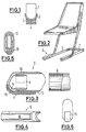
- Figure 1 first shows the pure principle of how the invention works.
- a furniture foot 1 for example the leg of a piece of furniture, is with
- a fastening device 2 adapted to the shape of the furniture foot
- the furniture foot 1 facing away from the tough elastic material can then still with a Reinforcement 4 may be connected.
- This reinforcement can come from another also a hard material. With unequal distribution of forces resulting pressures are in the tough elastic material of the overlay 3 recorded and balanced.
- FIG. 2 shows a chair as it should serve as an example of an application for the following description.
- the chair contains a furniture base 5 in the form of a U s lying on the floor.
- the free ends of the two legs are directed towards the front, and there each provided with a bacteriagleiter6 according to the invention.
- the rear ends of the webs of the U s are connected by a cross bar 7, so that there are two corners on which other furniture gliders are attached can be.
- This second type of furniture glider is shown in FIGS. 7 to 11, while FIGS. 3 to 6, to which reference is now made, represent the furniture glider 6 for the front ends of the profile.
- the furniture base 5 consists of a cross-sectionally oval metal profile 8, which in Figure 3 is shown in section on the right.
- the furniture glider 6 is pushed onto this. It has a shape corresponding to the cross section of the metal profile 8 and completely surrounds the scope of the profile.
- the furniture glider 6 is open. Shows one inside cylindrical approach 9, one opposite the outer wall 10 of the slider Gap 11, which is about the thickness of the metal of the metal profile 8 corresponds.
- On the outside of the neck 9 are individual in the longitudinal direction extending ribs 12 are formed, leading to an increased fixing of the glider on the metal profile 8.
- a support layer 15 is attached, for example by vulcanizing.
- the support layer 15 consists of a tough elastic Material. It can be inserted into a groove 16 for a better connection be, see the section of Figure 5.
- FIG. 4 shows the bottom view of the furniture glider 6 from below in FIG. 3
- Support layer 15 extends over almost the entire length of the furniture glider 6 and goes into the front, left in Figures 3 and 4, in a curved Arch over.
- This front is shown in detail in the front view of FIG. 6.
- the support layer 15 extends to almost half of the vertical extent of the furniture glider.
- the furniture glider 20 has an arc shape when viewed from above and contains a groove 21, which corresponds to the width of the metal profile 8.
- a groove 21 On the bottom of the groove 21 are two resilient upward-directed circular-cylindrical lugs 22 unshaped, which engage in corresponding holes in the underside of the metal profile 8 can.
- the groove is delimited by an inner wall 23 and an outer wall 24.
- the outer wall 24, see also FIG. 7, also runs in the form of an arc and contains a reinforcing rib 25 in the middle.
- FIG 7 in turn contains a support layer in a recess 26 27 made of the same or a similar material as the overlay layer 15 of the furniture glider 6 of Figures 3 to 6.
- Figure 10 and Figure 11 is the outside of the furniture foot shown on the right, also in Figure 9. You can choose from both Steps see that here too the contact surface 27 extends over the outer edge rounded out a little upwards, i.e. to the side of the furniture base, extends.
Landscapes
- Legs For Furniture In General (AREA)
Abstract
Description
- Figur 1
- schematisch das Prinzip der Wirkungsweise des von der Erfindung vorgeschlagenen Möbelgleiter;
- Figur 2
- ein Beispiel eines Stuhls, bei dem ein solcher Möbelgleiter verwendet werden kann;
- Figur 3
- einen Längsschnitt durch einen Möbelgleiter für die Vorderseite eines Stuhls;
- Figur 4
- die Ansicht des Möbelgleiters der Figur 3 von unten;
- Figur 5
- einen Querschnitt durch den Möbelgleiter;
- Figur 6
- eine Stirnansicht des Möbelgleiters der Figur 3;
- Figur 7
- die Seitenansicht eines Möbelgleiters für den hinteren Bereich eines Möbelfußes;
- Figur 8
- die Draufsicht auf den Möbelgleiter der Figur 7;
- Figur 9
- eine perspektivische Ansicht eines Möbelgleiters der Figur 7 und 8;
- Figur 10
- einen ersten Querschnitt durch den Möbelgleiter der Figur 7 und 8;
- Figur 11
- einen zweiten Querschnitt durch den Möbelgleiter.
nach vorne gerichtet, und dort mit jeweils einem Möbelgleiter6 nach der Erfindung versehen. Die hinteren Enden der Stege des U s sind durch einen Quersteg 7 verbunden, so dass dort zwei Ecken entstehen, an denen andere Möbelgleiter angebracht
werden können. Diese zweite Art von Möbelgleiter ist in den Figuren 7 bis 11 dargestellt, während die Figuren 3 bis 6, auf die jetzt Bezug genommen wird, den Möbelgleiter 6 für die vorderen Enden des Profils darstellen.
Claims (11)
- Möbelgleiter, insbesondere für Sitzmöbel, mit1.1 einer Befestigungseinrichtung zur Anbringung des Gleiters (6, 20) an einem Möbelstück,1.2 einer an der Unterseite des Gleiters (6, 20) angeordneten Auflageschicht (15, 27) aus zähelastischem Werkstoff, die1.2.1 derart ausgebildet und angeordnet ist, dass1.2.2 keine direkte Berührung zwischen dem Möbel-stück und dem Fußboden auftritt.
- Möbelgleiter nach Anspruch 1, bei dem die Auflageschicht (15, 27) eine Auflagefläche zur Auflage auf dem Fußboden bildet.
- Möbelgleiter nach Anspruch 1, bei dem an der Unterseite der Auflageschicht (15, 27) eine Verstärkung aus einem anderen Material angeordnet ist, das die Auflagefläche bildet.
- Möbelgleiter nach Anspruch 3, bei dem die Verstärkung aus Filz, Holz, Edelstahl, Stahldrahtgeflecht oder Gliedermaterial aufgebaut ist.
- Möbelgleiter nach einem der vorhergehenden Ansprüche, bei dem die Befestigungseinrichtung von einer Aufnahme für einen Möbelfuß gebildet wird.
- Möbelgleiter nach Anspruch 5, bei dem der Möbelfuß in der Aufnahme form- und/oder kraftschlüssig aufgenommen ist.
- Möbelgleiter nach einem der vorhergehenden Ansprüche, bei dem sich die Auflageschicht (15, 27) und/oder die Auflagefläche über mindestens eine Kante des Möbelfußes hinaus bis zur Seite des Möbelstücks erstreckt, vorzugsweise in abgerundeter Form.
- Möbelgleiter nach einem der vorhergehenden Ansprüche, bei dem bei einem Sitzmöbel die Auflagefläche über die Vorderkante des Sitzmöbels hinaus bzw. die Hinterkante des Sitzmöbels hinaus verläuft.
- Möbelgleiter nach einem der vorhergehenden Ansprüche, bei dem die Befestigungseinrichtung aus hartem Material besteht.
- Möbelgleiter nach einem der vorhergehenden Ansprüche, bei dem die Befestigungseinrichtung aus Kunststoff besteht.
- Möbelgleiter nach einem der vorhergehenden Ansprüche, bei dem die Auflageschicht (15, 27) mit der Befestigungseinrichtung unzertrennbar verbunden ist.
Applications Claiming Priority (2)
| Application Number | Priority Date | Filing Date | Title |
|---|---|---|---|
| DE2000149294 DE10049294A1 (de) | 2000-10-04 | 2000-10-04 | Möbelgleiter |
| DE10049294 | 2000-10-04 |
Publications (2)
| Publication Number | Publication Date |
|---|---|
| EP1195114A1 true EP1195114A1 (de) | 2002-04-10 |
| EP1195114B1 EP1195114B1 (de) | 2013-02-20 |
Family
ID=7658759
Family Applications (1)
| Application Number | Title | Priority Date | Filing Date |
|---|---|---|---|
| EP20010122407 Expired - Lifetime EP1195114B1 (de) | 2000-10-04 | 2001-09-20 | Möbelgleiter |
Country Status (3)
| Country | Link |
|---|---|
| EP (1) | EP1195114B1 (de) |
| DE (1) | DE10049294A1 (de) |
| DK (1) | DK1195114T3 (de) |
Cited By (1)
| Publication number | Priority date | Publication date | Assignee | Title |
|---|---|---|---|---|
| EP2420161A1 (de) * | 2010-08-12 | 2012-02-22 | ASS Einrichtungssysteme GmbH | Bodenschoner für einen Stuhl |
Families Citing this family (3)
| Publication number | Priority date | Publication date | Assignee | Title |
|---|---|---|---|---|
| DE20215929U1 (de) | 2002-10-16 | 2002-12-19 | Sedus Stoll AG, 79761 Waldshut-Tiengen | Möbelgleiter |
| DE102012205639B4 (de) | 2012-04-05 | 2015-02-12 | Wagner System Gmbh | Möbelgleiter, insbesondere für Sitzmöbel |
| DE202012003477U1 (de) | 2012-04-05 | 2012-05-09 | Wagner System Gmbh | Möbelgleiter, insbesondere für Sitzmöbel |
Citations (4)
| Publication number | Priority date | Publication date | Assignee | Title |
|---|---|---|---|---|
| EP0279055A2 (de) * | 1987-01-08 | 1988-08-24 | VS Vereinigte Spezialmöbelfabriken Verwaltungs-GmbH | Rohrgestell, insbesondere Stuhl-Rohrgestell |
| US5191676A (en) * | 1991-12-13 | 1993-03-09 | Fixtures Manufacturing Corporation | Split hemisphere foot with cooperating snap-over retaining lips |
| CA2109408A1 (fr) | 1993-10-27 | 1995-04-28 | Martin Dumas | Tore de glissement arrime aux pattes d'un meuble |
| FR2763816A1 (fr) | 1997-05-29 | 1998-12-04 | Nicolas Reynaud | Patin elastomere/feutre pour meuble et charges |
Family Cites Families (7)
| Publication number | Priority date | Publication date | Assignee | Title |
|---|---|---|---|---|
| DE520407C (de) * | 1931-03-11 | Auguste Schweinitz Geb Saltat | Moebelgleiter | |
| DE7006083U (de) * | 1970-02-20 | 1970-07-16 | Mueller Heiner | Halterung fuer einem moebelschuh am moebelfuss. |
| DE2450496C3 (de) * | 1974-10-24 | 1979-02-01 | Hohenloher Schulmoebelfabrik Schaffitzel Kg, 7110 Oehringen | Gleiter für Möbelstücke, insbesondere für Schulertische und -Stühle |
| DE3225260C2 (de) * | 1982-07-06 | 1984-07-05 | Gebr. Thonet GmbH, 6000 Frankfurt | Gleiter aus Kunststoff |
| DE9207397U1 (de) * | 1992-06-01 | 1992-08-06 | Klotz, Manfred, 4790 Paderborn | Möbelgleitfuß |
| AT1057U1 (de) * | 1995-11-15 | 1996-10-25 | Mayr Johann | Möbelgleiter |
| DE29812854U1 (de) * | 1998-07-20 | 1999-12-02 | Gornott, Dietmar, Dipl.-Ing., 64291 Darmstadt | Bodenschoner |
-
2000
- 2000-10-04 DE DE2000149294 patent/DE10049294A1/de not_active Withdrawn
-
2001
- 2001-09-20 DK DK01122407T patent/DK1195114T3/da active
- 2001-09-20 EP EP20010122407 patent/EP1195114B1/de not_active Expired - Lifetime
Patent Citations (4)
| Publication number | Priority date | Publication date | Assignee | Title |
|---|---|---|---|---|
| EP0279055A2 (de) * | 1987-01-08 | 1988-08-24 | VS Vereinigte Spezialmöbelfabriken Verwaltungs-GmbH | Rohrgestell, insbesondere Stuhl-Rohrgestell |
| US5191676A (en) * | 1991-12-13 | 1993-03-09 | Fixtures Manufacturing Corporation | Split hemisphere foot with cooperating snap-over retaining lips |
| CA2109408A1 (fr) | 1993-10-27 | 1995-04-28 | Martin Dumas | Tore de glissement arrime aux pattes d'un meuble |
| FR2763816A1 (fr) | 1997-05-29 | 1998-12-04 | Nicolas Reynaud | Patin elastomere/feutre pour meuble et charges |
Cited By (1)
| Publication number | Priority date | Publication date | Assignee | Title |
|---|---|---|---|---|
| EP2420161A1 (de) * | 2010-08-12 | 2012-02-22 | ASS Einrichtungssysteme GmbH | Bodenschoner für einen Stuhl |
Also Published As
| Publication number | Publication date |
|---|---|
| DE10049294A1 (de) | 2002-05-08 |
| EP1195114B1 (de) | 2013-02-20 |
| DK1195114T3 (da) | 2013-05-06 |
Similar Documents
| Publication | Publication Date | Title |
|---|---|---|
| DE1930583C3 (de) | Gepolstertes Sitzmöbel | |
| DE69301719T2 (de) | Bettgestell | |
| DE3904248A1 (de) | Gleitanordnung fuer fahrzeugsitzverstellung | |
| EP1493880A2 (de) | Fussbodenleiste | |
| EP1195114B1 (de) | Möbelgleiter | |
| DE3511302A1 (de) | Rost oder matte als bodenbelag | |
| DE202009004823U1 (de) | Sitzmöbel mit zusätzlicher Kippelfunktion | |
| DE19526437C2 (de) | Stuhl, insbesondere Reihenstuhl | |
| EP2420161B1 (de) | Bodenschoner für einen Stuhl | |
| DE8801405U1 (de) | Sitz | |
| DE29812071U1 (de) | Sofa | |
| DE29921260U1 (de) | Sitz-Liegemöbel mit steckbarem Seitenteil | |
| CH342710A (de) | Kufenstuhl | |
| AT404787B (de) | Sitzmöbel | |
| DE2421970A1 (de) | Sitz- bzw. liegemoebel | |
| DE102012205639B4 (de) | Möbelgleiter, insbesondere für Sitzmöbel | |
| DE4115506C2 (de) | Zerlegbares Sitzmöbel | |
| DE2541333A1 (de) | Drehstuhl | |
| DE102009056762B4 (de) | Stuhl mit einer Buchablage | |
| DE102004049494B4 (de) | Rückhalteprofil | |
| DE3003037A1 (de) | Moebelstueck | |
| DE1964459A1 (de) | Klappbares Moebel | |
| DE102021112432A1 (de) | Sitzmöbel | |
| DE1778480C3 (de) | Kufenstuhl in Stahlkonstruktion | |
| DE29901515U1 (de) | Sitzmöbel |
Legal Events
| Date | Code | Title | Description |
|---|---|---|---|
| PUAI | Public reference made under article 153(3) epc to a published international application that has entered the european phase |
Free format text: ORIGINAL CODE: 0009012 |
|
| AK | Designated contracting states |
Kind code of ref document: A1 Designated state(s): AT BE CH CY DE DK ES FI FR GB GR IE IT LI LU MC NL PT SE TR |
|
| AX | Request for extension of the european patent |
Free format text: AL;LT;LV;MK;RO;SI |
|
| 17P | Request for examination filed |
Effective date: 20021009 |
|
| AKX | Designation fees paid |
Free format text: AT BE CH CY DE DK ES FI FR GB GR IE IT LI LU MC NL PT SE TR |
|
| RAP1 | Party data changed (applicant data changed or rights of an application transferred) |
Owner name: VS VEREINIGTE SPEZIALMOEBELFABRIKEN GMBH & CO. KG |
|
| GRAP | Despatch of communication of intention to grant a patent |
Free format text: ORIGINAL CODE: EPIDOSNIGR1 |
|
| GRAS | Grant fee paid |
Free format text: ORIGINAL CODE: EPIDOSNIGR3 |
|
| GRAA | (expected) grant |
Free format text: ORIGINAL CODE: 0009210 |
|
| AK | Designated contracting states |
Kind code of ref document: B1 Designated state(s): AT BE CH CY DE DK ES FI FR GB GR IE IT LI LU MC NL PT SE TR |
|
| REG | Reference to a national code |
Ref country code: GB Ref legal event code: FG4D Free format text: NOT ENGLISH |
|
| REG | Reference to a national code |
Ref country code: CH Ref legal event code: EP |
|
| REG | Reference to a national code |
Ref country code: AT Ref legal event code: REF Ref document number: 597134 Country of ref document: AT Kind code of ref document: T Effective date: 20130315 |
|
| REG | Reference to a national code |
Ref country code: IE Ref legal event code: FG4D Free format text: LANGUAGE OF EP DOCUMENT: GERMAN |
|
| REG | Reference to a national code |
Ref country code: DE Ref legal event code: R096 Ref document number: 50116245 Country of ref document: DE Effective date: 20130418 |
|
| REG | Reference to a national code |
Ref country code: DK Ref legal event code: T3 |
|
| REG | Reference to a national code |
Ref country code: CH Ref legal event code: NV Representative=s name: HEPP WENGER RYFFEL AG, CH |
|
| REG | Reference to a national code |
Ref country code: NL Ref legal event code: T3 |
|
| PG25 | Lapsed in a contracting state [announced via postgrant information from national office to epo] |
Ref country code: SE Free format text: LAPSE BECAUSE OF FAILURE TO SUBMIT A TRANSLATION OF THE DESCRIPTION OR TO PAY THE FEE WITHIN THE PRESCRIBED TIME-LIMIT Effective date: 20130220 Ref country code: CY Free format text: LAPSE BECAUSE OF FAILURE TO SUBMIT A TRANSLATION OF THE DESCRIPTION OR TO PAY THE FEE WITHIN THE PRESCRIBED TIME-LIMIT Effective date: 20130220 Ref country code: ES Free format text: LAPSE BECAUSE OF FAILURE TO SUBMIT A TRANSLATION OF THE DESCRIPTION OR TO PAY THE FEE WITHIN THE PRESCRIBED TIME-LIMIT Effective date: 20130531 |
|
| PG25 | Lapsed in a contracting state [announced via postgrant information from national office to epo] |
Ref country code: PT Free format text: LAPSE BECAUSE OF FAILURE TO SUBMIT A TRANSLATION OF THE DESCRIPTION OR TO PAY THE FEE WITHIN THE PRESCRIBED TIME-LIMIT Effective date: 20130620 Ref country code: FI Free format text: LAPSE BECAUSE OF FAILURE TO SUBMIT A TRANSLATION OF THE DESCRIPTION OR TO PAY THE FEE WITHIN THE PRESCRIBED TIME-LIMIT Effective date: 20130220 Ref country code: GR Free format text: LAPSE BECAUSE OF FAILURE TO SUBMIT A TRANSLATION OF THE DESCRIPTION OR TO PAY THE FEE WITHIN THE PRESCRIBED TIME-LIMIT Effective date: 20130521 |
|
| PLBE | No opposition filed within time limit |
Free format text: ORIGINAL CODE: 0009261 |
|
| STAA | Information on the status of an ep patent application or granted ep patent |
Free format text: STATUS: NO OPPOSITION FILED WITHIN TIME LIMIT |
|
| PG25 | Lapsed in a contracting state [announced via postgrant information from national office to epo] |
Ref country code: IT Free format text: LAPSE BECAUSE OF FAILURE TO SUBMIT A TRANSLATION OF THE DESCRIPTION OR TO PAY THE FEE WITHIN THE PRESCRIBED TIME-LIMIT Effective date: 20130220 |
|
| 26N | No opposition filed |
Effective date: 20131121 |
|
| REG | Reference to a national code |
Ref country code: DE Ref legal event code: R097 Ref document number: 50116245 Country of ref document: DE Effective date: 20131121 |
|
| PG25 | Lapsed in a contracting state [announced via postgrant information from national office to epo] |
Ref country code: MC Free format text: LAPSE BECAUSE OF FAILURE TO SUBMIT A TRANSLATION OF THE DESCRIPTION OR TO PAY THE FEE WITHIN THE PRESCRIBED TIME-LIMIT Effective date: 20130220 |
|
| REG | Reference to a national code |
Ref country code: DE Ref legal event code: R082 Ref document number: 50116245 Ref country code: DE Ref legal event code: R082 Ref document number: 50116245 Country of ref document: DE Representative=s name: PRUEFER & PARTNER MBB PATENTANWAELTE RECHTSANW, DE Country of ref document: DE Representative=s name: PRUEFER & PARTNER GBR, DE |
|
| REG | Reference to a national code |
Ref country code: FR Ref legal event code: PLFP Year of fee payment: 15 |
|
| PGFP | Annual fee paid to national office [announced via postgrant information from national office to epo] |
Ref country code: CH Payment date: 20150922 Year of fee payment: 15 Ref country code: GB Payment date: 20150922 Year of fee payment: 15 Ref country code: IE Payment date: 20150928 Year of fee payment: 15 Ref country code: LU Payment date: 20150922 Year of fee payment: 15 |
|
| PGFP | Annual fee paid to national office [announced via postgrant information from national office to epo] |
Ref country code: AT Payment date: 20150921 Year of fee payment: 15 Ref country code: FR Payment date: 20150923 Year of fee payment: 15 Ref country code: BE Payment date: 20150921 Year of fee payment: 15 |
|
| PGFP | Annual fee paid to national office [announced via postgrant information from national office to epo] |
Ref country code: DK Payment date: 20150923 Year of fee payment: 15 |
|
| PGFP | Annual fee paid to national office [announced via postgrant information from national office to epo] |
Ref country code: NL Payment date: 20150923 Year of fee payment: 15 |
|
| PG25 | Lapsed in a contracting state [announced via postgrant information from national office to epo] |
Ref country code: BE Free format text: LAPSE BECAUSE OF NON-PAYMENT OF DUE FEES Effective date: 20160930 |
|
| REG | Reference to a national code |
Ref country code: DK Ref legal event code: EBP Effective date: 20160930 |
|
| REG | Reference to a national code |
Ref country code: CH Ref legal event code: PL |
|
| REG | Reference to a national code |
Ref country code: NL Ref legal event code: MM Effective date: 20161001 |
|
| REG | Reference to a national code |
Ref country code: AT Ref legal event code: MM01 Ref document number: 597134 Country of ref document: AT Kind code of ref document: T Effective date: 20160920 |
|
| GBPC | Gb: european patent ceased through non-payment of renewal fee |
Effective date: 20160920 |
|
| REG | Reference to a national code |
Ref country code: IE Ref legal event code: MM4A |
|
| PG25 | Lapsed in a contracting state [announced via postgrant information from national office to epo] |
Ref country code: NL Free format text: LAPSE BECAUSE OF NON-PAYMENT OF DUE FEES Effective date: 20161001 |
|
| REG | Reference to a national code |
Ref country code: FR Ref legal event code: ST Effective date: 20170531 |
|
| PG25 | Lapsed in a contracting state [announced via postgrant information from national office to epo] |
Ref country code: FR Free format text: LAPSE BECAUSE OF NON-PAYMENT OF DUE FEES Effective date: 20160930 Ref country code: CH Free format text: LAPSE BECAUSE OF NON-PAYMENT OF DUE FEES Effective date: 20160930 Ref country code: IE Free format text: LAPSE BECAUSE OF NON-PAYMENT OF DUE FEES Effective date: 20160920 Ref country code: LI Free format text: LAPSE BECAUSE OF NON-PAYMENT OF DUE FEES Effective date: 20160930 Ref country code: GB Free format text: LAPSE BECAUSE OF NON-PAYMENT OF DUE FEES Effective date: 20160920 |
|
| PG25 | Lapsed in a contracting state [announced via postgrant information from national office to epo] |
Ref country code: AT Free format text: LAPSE BECAUSE OF NON-PAYMENT OF DUE FEES Effective date: 20160920 Ref country code: LU Free format text: LAPSE BECAUSE OF NON-PAYMENT OF DUE FEES Effective date: 20160920 |
|
| REG | Reference to a national code |
Ref country code: BE Ref legal event code: MM Effective date: 20160930 |
|
| PG25 | Lapsed in a contracting state [announced via postgrant information from national office to epo] |
Ref country code: DK Free format text: LAPSE BECAUSE OF NON-PAYMENT OF DUE FEES Effective date: 20160930 |
|
| PGFP | Annual fee paid to national office [announced via postgrant information from national office to epo] |
Ref country code: TR Payment date: 20150920 Year of fee payment: 15 |
|
| REG | Reference to a national code |
Ref legal event code: R082 Country of ref document: DE Representative=s name: PAGE, WHITE & FARRER GERMANY LLP, DE Ref country code: DE Ref document number: 50116245 |
|
| REG | Reference to a national code |
Ref country code: DE Ref legal event code: R082 Ref document number: 50116245 Country of ref document: DE Representative=s name: PAGE, WHITE & FARRER GERMANY LLP, DE |
|
| PGFP | Annual fee paid to national office [announced via postgrant information from national office to epo] |
Ref country code: DE Payment date: 20200813 Year of fee payment: 20 |
|
| REG | Reference to a national code |
Ref country code: DE Ref legal event code: R071 Ref document number: 50116245 Country of ref document: DE |
|
| PG25 | Lapsed in a contracting state [announced via postgrant information from national office to epo] |
Ref country code: TR Free format text: LAPSE BECAUSE OF NON-PAYMENT OF DUE FEES Effective date: 20160920 |