EP1191162A2 - Verfahren zur Herstellung von zugänglichen abgehängten Decken und dafür verwendbares Profilsystem - Google Patents
Verfahren zur Herstellung von zugänglichen abgehängten Decken und dafür verwendbares Profilsystem Download PDFInfo
- Publication number
- EP1191162A2 EP1191162A2 EP01122375A EP01122375A EP1191162A2 EP 1191162 A2 EP1191162 A2 EP 1191162A2 EP 01122375 A EP01122375 A EP 01122375A EP 01122375 A EP01122375 A EP 01122375A EP 1191162 A2 EP1191162 A2 EP 1191162A2
- Authority
- EP
- European Patent Office
- Prior art keywords
- profile
- profiles
- plate
- ceiling
- elements
- Prior art date
- Legal status (The legal status is an assumption and is not a legal conclusion. Google has not performed a legal analysis and makes no representation as to the accuracy of the status listed.)
- Granted
Links
Images


Classifications
-
- E—FIXED CONSTRUCTIONS
- E04—BUILDING
- E04B—GENERAL BUILDING CONSTRUCTIONS; WALLS, e.g. PARTITIONS; ROOFS; FLOORS; CEILINGS; INSULATION OR OTHER PROTECTION OF BUILDINGS
- E04B9/00—Ceilings; Construction of ceilings, e.g. false ceilings; Ceiling construction with regard to insulation
- E04B9/06—Ceilings; Construction of ceilings, e.g. false ceilings; Ceiling construction with regard to insulation characterised by constructional features of the supporting construction, e.g. cross section or material of framework members
- E04B9/064—Ceilings; Construction of ceilings, e.g. false ceilings; Ceiling construction with regard to insulation characterised by constructional features of the supporting construction, e.g. cross section or material of framework members comprising extruded supporting beams
-
- E—FIXED CONSTRUCTIONS
- E04—BUILDING
- E04B—GENERAL BUILDING CONSTRUCTIONS; WALLS, e.g. PARTITIONS; ROOFS; FLOORS; CEILINGS; INSULATION OR OTHER PROTECTION OF BUILDINGS
- E04B9/00—Ceilings; Construction of ceilings, e.g. false ceilings; Ceiling construction with regard to insulation
- E04B9/003—Ceilings; Construction of ceilings, e.g. false ceilings; Ceiling construction with regard to insulation with movable parts, e.g. pivoting panels, access doors
-
- E—FIXED CONSTRUCTIONS
- E04—BUILDING
- E04B—GENERAL BUILDING CONSTRUCTIONS; WALLS, e.g. PARTITIONS; ROOFS; FLOORS; CEILINGS; INSULATION OR OTHER PROTECTION OF BUILDINGS
- E04B9/00—Ceilings; Construction of ceilings, e.g. false ceilings; Ceiling construction with regard to insulation
- E04B9/04—Ceilings; Construction of ceilings, e.g. false ceilings; Ceiling construction with regard to insulation comprising slabs, panels, sheets or the like
- E04B9/0428—Ceilings; Construction of ceilings, e.g. false ceilings; Ceiling construction with regard to insulation comprising slabs, panels, sheets or the like having a closed frame around the periphery
-
- E—FIXED CONSTRUCTIONS
- E04—BUILDING
- E04B—GENERAL BUILDING CONSTRUCTIONS; WALLS, e.g. PARTITIONS; ROOFS; FLOORS; CEILINGS; INSULATION OR OTHER PROTECTION OF BUILDINGS
- E04B9/00—Ceilings; Construction of ceilings, e.g. false ceilings; Ceiling construction with regard to insulation
- E04B9/04—Ceilings; Construction of ceilings, e.g. false ceilings; Ceiling construction with regard to insulation comprising slabs, panels, sheets or the like
- E04B9/0435—Ceilings; Construction of ceilings, e.g. false ceilings; Ceiling construction with regard to insulation comprising slabs, panels, sheets or the like having connection means at the edges
-
- E—FIXED CONSTRUCTIONS
- E04—BUILDING
- E04B—GENERAL BUILDING CONSTRUCTIONS; WALLS, e.g. PARTITIONS; ROOFS; FLOORS; CEILINGS; INSULATION OR OTHER PROTECTION OF BUILDINGS
- E04B9/00—Ceilings; Construction of ceilings, e.g. false ceilings; Ceiling construction with regard to insulation
- E04B9/04—Ceilings; Construction of ceilings, e.g. false ceilings; Ceiling construction with regard to insulation comprising slabs, panels, sheets or the like
- E04B9/0464—Ceilings; Construction of ceilings, e.g. false ceilings; Ceiling construction with regard to insulation comprising slabs, panels, sheets or the like having irregularities on the faces, e.g. holes, grooves
-
- E—FIXED CONSTRUCTIONS
- E04—BUILDING
- E04B—GENERAL BUILDING CONSTRUCTIONS; WALLS, e.g. PARTITIONS; ROOFS; FLOORS; CEILINGS; INSULATION OR OTHER PROTECTION OF BUILDINGS
- E04B9/00—Ceilings; Construction of ceilings, e.g. false ceilings; Ceiling construction with regard to insulation
- E04B9/18—Means for suspending the supporting construction
- E04B9/183—Means for suspending the supporting construction having a lower side adapted to be connected to a channel of the supporting construction
-
- E—FIXED CONSTRUCTIONS
- E04—BUILDING
- E04B—GENERAL BUILDING CONSTRUCTIONS; WALLS, e.g. PARTITIONS; ROOFS; FLOORS; CEILINGS; INSULATION OR OTHER PROTECTION OF BUILDINGS
- E04B9/00—Ceilings; Construction of ceilings, e.g. false ceilings; Ceiling construction with regard to insulation
- E04B9/18—Means for suspending the supporting construction
- E04B9/20—Means for suspending the supporting construction adjustable
-
- E—FIXED CONSTRUCTIONS
- E04—BUILDING
- E04B—GENERAL BUILDING CONSTRUCTIONS; WALLS, e.g. PARTITIONS; ROOFS; FLOORS; CEILINGS; INSULATION OR OTHER PROTECTION OF BUILDINGS
- E04B9/00—Ceilings; Construction of ceilings, e.g. false ceilings; Ceiling construction with regard to insulation
- E04B9/22—Connection of slabs, panels, sheets or the like to the supporting construction
- E04B9/28—Connection of slabs, panels, sheets or the like to the supporting construction with the slabs, panels, sheets or the like having grooves engaging with horizontal flanges of the supporting construction or accessory means connected thereto
Definitions
- the present invention relates to a method for producing accessible suspended ceilings made of plate elements with grooves and Fastening elements in the form of profile systems, the profile systems being made of a first profile that can be hung from the ceiling and one that is open at the top Channel and a second profile that can be hooked into this channel of the first profile exist and both profiles on the top a plate and on the bottom as have spring-acting L-shaped extension.
- Suspended accessible ceilings have so far been produced by the attachment a frame suspended from the ceiling, into which the plate elements be inserted.
- the plate elements are preferably with a metal sheet flanged so that they are not damaged by the frame.
- a suspended ceiling is preferably made of metal, in which the individual elements by simply laying them on by themselves concealed mounting rails are mutually fixed and adjustable in height Tensioners attached to the load-bearing ceiling and by horizontal Connection struts are stiffened and spaced apart.
- a removable ceiling mount is known from GB-1 493 737 which mineral fiber boards can be inserted, the suspension via Z-shaped holders, which are deliberately offset laterally, each one Being able to remove the plate unhindered.
- Both profiles had a plate on the top and L-shaped ones on the bottom Extensions that acted as a spring. This feather could be in Plate elements with grooves can be installed.
- the hanging profile pointed from the outer edge inwards displaces a vertical plate with a round thickening at the top. At this thickening could Clamping elements are attached using a wire rope and hoes connected to the ceiling. The height adjustment was done through the wire rope and the clamping element.
- This hanging profile had one open channel upwards, in which a second profile is hung could. This resulted in alternating hanging on the ceiling Plate elements and only suspended plate elements in between, the were easy to remove, leaving the space between the ceiling and Plate elements became accessible.
- This profile system is shown in Figures 5,6 and 7.
- the invention has therefore set itself the task of producing of accessible suspended ceilings made of panel elements with grooves and To simplify fasteners in the form of profile systems and before all once a height adjustment can not be changed, so that at a later opening and closing of the suspended ceilings on a new height adjustment can be dispensed with.
- the ends of the profiles and thus of the plate elements are preferably rigid but reversibly connected. This is achieved in that the Profiles have a round or angular cavity at least at their ends have, in which a displaceable and fixable metal rod inserted becomes.
- the second profile then preferably has both on the plate and on the part of the L-shaped extension acting as a spring which is the same distance from the contact surface of the two profiles have, such as the limitation of the gutter.
- the first profiles are preferably attached to the ceiling by means of Threaded rods and snail picks. This creates a suspension on the Ceiling, which after a single height adjustment even when the later expansion Plate elements maintain the height adjustment.
- the suspension device of the first profile can also facilitate the profile be designed to be removable. The only thing that matters is that through installation and expansion the plate elements will not lose the height adjustment later. Still is the profile system according to the invention is easy to install height adjustable and can also be readjusted later if necessary.
- the suspended panel elements but also the suspended panel elements can be rigidly but reversibly connected to each other at their ends be, for example, by a movable and fixable metal rod.
- Plate elements on fiber-reinforced plaster are particularly preferred, if desired, these plate elements also have holes or grooves can.
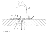
- Figure 1 shows a section through a usable according to the invention Profile system, which is designed to be removable.
- Figure 2 shows another embodiment, which by means of threaded rods and snail hooks can be hung.
- Figure 3 shows a ceiling mount for this profile, in which the Profile system can be detachably attached.
- Figures 4 and 4a show another embodiment in which the Attachment of the first profile with the ceiling is designed to be displaceable. figure 4 shows this configuration in the suspended state and FIG. 4a not hung condition.
- FIGS. 5, 6 and 7 show the prior art from Boscetti, von which only a sample exists in the hands of the applicant.
Abstract
Description
Claims (12)
- Verfahren zur Herstellung von zugänglichen, abgehängten Decken aus Plattenelementen (P) mit Nuten und Befestigungselementen in Form von Profilsystemen, wobei die Profilsysteme aus einem ersten an der Decke aufhängbaren Profil (1) und einer nach oben offenen Rinne (2) und einem zweiten in diese Rinne des ersten Profils einhängbaren Profil (3) bestehen und beide Profile an der Oberseite eine Platte (4) und an der Unterseite als Feder wirkende L-förmige Erweiterungen (5) aufweisen, dadurch gekennzeichnet, dass zunächst ein oder mehrere Plattenelemente (P) mit zwei ersten Profilen (1) oberhalb der späteren Berührungsflächen mit den zweiten Profilen (3) starr, höhenjustierbar aber abnehmbar an der Decke befestigt werden, dann in Abständen der Breite der Plattenelemente weitere Plattenelemente mit jeweils zwei ersten Profilen (1) oberhalb der späteren Berührungsflächen mit den zweiten Profilen starr, höhenjustierbar aber abnehmbar an der Decke befestigt werden und danach in den Lücken Plattenelemente mit zwei zweiten Profilen (3) eingehängt werden.
- Verfahren gemäß Anspruch 1, dadurch gekennzeichnet, dass die Enden der Profile starr, aber reversibel miteinander verbunden werden.
- Verfahren gemäß Anspruch 1 oder 2, dadurch gekennzeichnet, dass die Rinne des ersten Profils und die Einhängung des zweiten Profils zwischen der Oberkante der Platte und der Nut der Plattenelemente angebracht sind.
- Verfahren gemäß einem der Ansprüche 1-3, dadurch gekennzeichnet, dass das zweite Profil sowohl an der Platte als auch auf dem als Feder wirkenden Teil der L-förmigen Erweiterung Begrenzungsnoppen (6) aufweist, welche den gleichen Abstand von der Berührungsfläche der beiden Profile aufweisen wie die Begrenzung der Rinne.
- Verfahren gemäß einem der Ansprüche 1-4, dadurch gekennzeichnet, dass die Verbindung der Enden der Profile durch einen verschiebbaren und fixierbaren Metallstab erfolgt.
- Verfahren gemäß einem der Ansprüche 1-5, dadurch gekennzeichnet, dass die Befestigung der ersten Profile mit der Decke mittels Gewindestäben und Schneckenhaken erfolgt.
- Verfahren gemäß einem der Ansprüche 1-6, dadurch gekennzeichnet, dass die Befestigung der ersten Profile mit der Decke verschiebbar ausgestaltet ist.
- Profilsystem für abgehängte Decken aus Plattenelementen (P) mit Nuten bestehend aus einem ersten an der Decke aufhängbar ausgestalteten Profil (1) mit einer nach oben offenen Rinne (2) und einem zweiten in diese Rinne des ersten Profils einhängbaren Profil (3), wobei beide Profile an der Oberseite eine Platte (4) und auf der Unterseite als Feder wirkende L-förmige Erweiterungen (5) aufweisen, in welche die Nuten der Plattenelemente einführbar sind, wobei die Aufhängvorrichtung (7) des ersten Profils soweit zum zweiten Profil herüberragt, dass die Befestigung an der Decke jeweils genau oberhalb der Berührungsfläche der beiden Profile erfolgen kann.
- Profilsystem gemäß Anspruch 8, dadurch gekennzeichnet, dass die offene Rinne des aufhängbaren ersten Profils (1) und die Einhängung des zweiten Profils (3) zwischen der Oberkante der Platte und der Nut des Plattenelements angebracht sind.
- Profilsystem gemäß Anspruch 9, dadurch gekennzeichnet, dass das zweite Profil (3) sowohl an der Platte als auch auf dem als Feder wirkenden Teil der L-förmigen Erweiterung Begrenzungsnoppen (6) aufweist, welche den gleichen Abstand von der Berührungsfläche der beiden Profile aufweisen wie die Begrenzung der Rinne.
- Profilsystem gemäß einem der Ansprüche 8-10, dadurch gekennzeichnet, dass die Profile mindestens an ihren Enden einen runden oder eckigen Hohlraum aufweisen.
- Profilsystem gemäß einem der Ansprüche 7-10, dadurch gekennzeichnet, dass die Aufhängvorrichtung des ersten Profils abnehmbar ausgestaltet ist.
Applications Claiming Priority (2)
| Application Number | Priority Date | Filing Date | Title |
|---|---|---|---|
| DE10046430 | 2000-09-20 | ||
| DE10046430 | 2000-09-20 |
Publications (3)
| Publication Number | Publication Date |
|---|---|
| EP1191162A2 true EP1191162A2 (de) | 2002-03-27 |
| EP1191162A3 EP1191162A3 (de) | 2003-07-16 |
| EP1191162B1 EP1191162B1 (de) | 2007-11-14 |
Family
ID=7656853
Family Applications (1)
| Application Number | Title | Priority Date | Filing Date |
|---|---|---|---|
| EP01122375A Expired - Lifetime EP1191162B1 (de) | 2000-09-20 | 2001-09-19 | Verfahren zur Herstellung von zugänglichen abgehängten Decken und dafür verwendbares Profilsystem |
Country Status (8)
| Country | Link |
|---|---|
| EP (1) | EP1191162B1 (de) |
| AT (1) | ATE378481T1 (de) |
| CZ (1) | CZ20013373A3 (de) |
| DE (1) | DE50113258D1 (de) |
| HU (1) | HUP0103734A2 (de) |
| NO (1) | NO20014552L (de) |
| PL (1) | PL349654A1 (de) |
| RU (1) | RU2215853C2 (de) |
Cited By (3)
| Publication number | Priority date | Publication date | Assignee | Title |
|---|---|---|---|---|
| WO2012171115A1 (en) | 2011-06-16 | 2012-12-20 | Les Plafonds Embassy Inc. | Trackless suspended ceiling |
| CN105649253A (zh) * | 2015-12-07 | 2016-06-08 | 浙江宝兰电气有限公司 | 一种集成吊顶结构 |
| US9783984B2 (en) | 2015-06-02 | 2017-10-10 | Awi Licensing Llc | Ceiling mounting system and related method |
Families Citing this family (2)
| Publication number | Priority date | Publication date | Assignee | Title |
|---|---|---|---|---|
| AU2008262258B2 (en) * | 2007-06-08 | 2014-05-22 | Armstrong World Industries, Inc. | Canopy system |
| RU2658927C1 (ru) * | 2017-09-21 | 2018-06-26 | Александр Васильевич Гущин | Универсальная декоративная подвесная рамочная потолочная и стеновая система |
Citations (2)
| Publication number | Priority date | Publication date | Assignee | Title |
|---|---|---|---|---|
| DE1938643A1 (de) | 1968-12-14 | 1970-06-18 | Picatoste Jose Lledo | Unterdecke |
| GB1493737A (en) | 1975-01-17 | 1977-11-30 | Thermo Acoustic Prod Ltd | Demountable ceiling assembly |
Family Cites Families (7)
| Publication number | Priority date | Publication date | Assignee | Title |
|---|---|---|---|---|
| GB833307A (en) * | 1958-03-25 | 1960-04-21 | Anders Palmer | Improvements in or relating to sub-ceiling panel |
| DE1189695B (de) * | 1958-04-30 | 1965-03-25 | Elektro Metall Kuersteiner & C | Unterdecke mit in einem tragenden Bauteil, z. B. einer Geschossdecke, verankerten Haengern |
| DE2162382A1 (de) * | 1971-12-16 | 1973-06-20 | Westag & Getalit Ag | Vorrichtung fuer die aufhaengung einer deckenverkleidung an ortsfesten gebaeudedecken |
| US3832816A (en) * | 1972-06-05 | 1974-09-03 | Chicago Metallic Corp | Concealed grid suspended ceiling structure with simplified installation |
| US3875717A (en) * | 1973-08-30 | 1975-04-08 | Wolfgang Moeller | Unitary device for joining removable ceiling tile to hanger member |
| US5893250A (en) * | 1997-10-31 | 1999-04-13 | Benvenuto; Guido | Drop ceiling system |
| EP0999317A1 (de) * | 1998-11-02 | 2000-05-10 | Giovanni Boschetti | Befestigungsmittel für Paneelelemente einer aufgehängten Decke an den Hängeelementen |
-
2001
- 2001-09-13 PL PL01349654A patent/PL349654A1/xx unknown
- 2001-09-19 EP EP01122375A patent/EP1191162B1/de not_active Expired - Lifetime
- 2001-09-19 NO NO20014552A patent/NO20014552L/no not_active Application Discontinuation
- 2001-09-19 DE DE50113258T patent/DE50113258D1/de not_active Expired - Lifetime
- 2001-09-19 CZ CZ20013373A patent/CZ20013373A3/cs unknown
- 2001-09-19 RU RU2001125689/03A patent/RU2215853C2/ru not_active IP Right Cessation
- 2001-09-19 AT AT01122375T patent/ATE378481T1/de active
- 2001-09-19 HU HU0103734A patent/HUP0103734A2/hu unknown
Patent Citations (2)
| Publication number | Priority date | Publication date | Assignee | Title |
|---|---|---|---|---|
| DE1938643A1 (de) | 1968-12-14 | 1970-06-18 | Picatoste Jose Lledo | Unterdecke |
| GB1493737A (en) | 1975-01-17 | 1977-11-30 | Thermo Acoustic Prod Ltd | Demountable ceiling assembly |
Cited By (5)
| Publication number | Priority date | Publication date | Assignee | Title |
|---|---|---|---|---|
| WO2012171115A1 (en) | 2011-06-16 | 2012-12-20 | Les Plafonds Embassy Inc. | Trackless suspended ceiling |
| EP2721226A1 (de) * | 2011-06-16 | 2014-04-23 | Les Plafonds Embassy Inc. | Selbsttragende hängedecke |
| EP2721226A4 (de) * | 2011-06-16 | 2015-03-11 | Plafonds Embassy Inc | Selbsttragende hängedecke |
| US9783984B2 (en) | 2015-06-02 | 2017-10-10 | Awi Licensing Llc | Ceiling mounting system and related method |
| CN105649253A (zh) * | 2015-12-07 | 2016-06-08 | 浙江宝兰电气有限公司 | 一种集成吊顶结构 |
Also Published As
| Publication number | Publication date |
|---|---|
| ATE378481T1 (de) | 2007-11-15 |
| EP1191162B1 (de) | 2007-11-14 |
| HUP0103734A2 (hu) | 2003-11-28 |
| EP1191162A3 (de) | 2003-07-16 |
| RU2215853C2 (ru) | 2003-11-10 |
| CZ20013373A3 (cs) | 2002-05-15 |
| NO20014552L (no) | 2002-03-21 |
| NO20014552D0 (no) | 2001-09-19 |
| PL349654A1 (en) | 2002-03-25 |
| HU0103734D0 (en) | 2001-11-28 |
| DE50113258D1 (de) | 2007-12-27 |
Similar Documents
| Publication | Publication Date | Title |
|---|---|---|
| EP2526235B1 (de) | Fassadendämmung | |
| WO1998049412A1 (de) | Vorrichtung zum befestigen von fassadenplatten | |
| DE3932176A1 (de) | Wandbekleidungselement, insbesondere fassadenelement | |
| DE3232106A1 (de) | Tragschiene oder -platte fuer eine vorgehaengte wand- oder deckenverkleidung | |
| EP1191162B1 (de) | Verfahren zur Herstellung von zugänglichen abgehängten Decken und dafür verwendbares Profilsystem | |
| DE2402585A1 (de) | Vorrichtung zum aufhaengen von fassadenplatten od. dgl. an baukoerpern | |
| DE19737515C2 (de) | Vorrichtung zur Befestigung von Bauteilen an und im Abstand zu einem Tragwerk, insbesondere von Längsprofilen an und im Abstand zu einer Bauwerkswand und dafür geeigneter Abstandhalter | |
| DE3246725A1 (de) | Aufhaengevorrichtung fuer wandbekleidungsplatten und unter verwendung derartiger aufhaengevorrichtungen aufgebaute plattenverankerungen | |
| DE102016118483A1 (de) | Fassadenplatten-Montagesystem | |
| DE202016007387U1 (de) | Universalhalterung für Gabionen und Gitterzäune | |
| DE19610364C2 (de) | Einstellbare Aufhängevorrichtung für an einer Wand zu befestigende Gegenstände | |
| EP3722528B1 (de) | Überdachung in form einer pergola, eines glasdachs oder eines wintergartens | |
| DE2219564C2 (de) | Aufhängevorrichtung für Bekleidungsplatten aus Beton o.dgl. | |
| DE2916925A1 (de) | Halterung fuer fassadenplatten | |
| DE19823173C2 (de) | Aufhängeleiste zum Aufhängen von Rahmen | |
| DE4000951A1 (de) | Aluminium-schienensystem zur montage von natursteinfassadenplatten | |
| DE3837990A1 (de) | Vorrichtung zur haengenden halterung, von langformteilen an gebaeudedecken | |
| AT202746B (de) | Einstellbare Hängevorrichtung für insbesondere untergehängte bzw. vorgesetzte Decken bzw. Wandteile | |
| DE2156757C3 (de) | Aufhängevorrichtung für Wandverkleidungsplatten | |
| DE2836817A1 (de) | Vorrichtung zur aufhaengung einer fassadenplatte an einem hinterluefteten baukoerper | |
| AT352356B (de) | Variable raumbegrenzung | |
| AT406437B (de) | Vorrichtung zur befestigung der frontblende einer schublade | |
| AT6423U1 (de) | Aufziebarer behang, insbesondere für ein fenster oder eine tür | |
| DE2002477C (de) | Aufhängevorrichtung für Wandverkleidungsplatten | |
| EP2843181B1 (de) | Haltevorrichtung für einen Gurtwickler |
Legal Events
| Date | Code | Title | Description |
|---|---|---|---|
| PUAI | Public reference made under article 153(3) epc to a published international application that has entered the european phase |
Free format text: ORIGINAL CODE: 0009012 |
|
| AK | Designated contracting states |
Kind code of ref document: A2 Designated state(s): AT BE CH CY DE DK ES FI FR GB GR IE IT LI LU MC NL PT SE TR |
|
| AX | Request for extension of the european patent |
Free format text: AL;LT;LV;MK;RO;SI |
|
| PUAL | Search report despatched |
Free format text: ORIGINAL CODE: 0009013 |
|
| AK | Designated contracting states |
Designated state(s): AT BE CH CY DE DK ES FI FR GB GR IE IT LI LU MC NL PT SE TR |
|
| AX | Request for extension of the european patent |
Extension state: AL LT LV MK RO SI |
|
| RAP1 | Party data changed (applicant data changed or rights of an application transferred) |
Owner name: KNAUF INTEGRAL KG |
|
| 17P | Request for examination filed |
Effective date: 20030816 |
|
| AKX | Designation fees paid |
Designated state(s): AT BE CH CY DE DK ES FI FR GB GR IE IT LI LU MC NL PT SE TR |
|
| AXX | Extension fees paid |
Extension state: LT Payment date: 20030816 |
|
| GRAP | Despatch of communication of intention to grant a patent |
Free format text: ORIGINAL CODE: EPIDOSNIGR1 |
|
| GRAS | Grant fee paid |
Free format text: ORIGINAL CODE: EPIDOSNIGR3 |
|
| GRAA | (expected) grant |
Free format text: ORIGINAL CODE: 0009210 |
|
| AK | Designated contracting states |
Kind code of ref document: B1 Designated state(s): AT BE CH CY DE DK ES FI FR GB GR IE IT LI LU MC NL PT SE TR |
|
| AX | Request for extension of the european patent |
Extension state: LT |
|
| REG | Reference to a national code |
Ref country code: GB Ref legal event code: FG4D Free format text: NOT ENGLISH |
|
| REG | Reference to a national code |
Ref country code: CH Ref legal event code: EP |
|
| REG | Reference to a national code |
Ref country code: IE Ref legal event code: FG4D Free format text: LANGUAGE OF EP DOCUMENT: GERMAN |
|
| REF | Corresponds to: |
Ref document number: 50113258 Country of ref document: DE Date of ref document: 20071227 Kind code of ref document: P |
|
| REG | Reference to a national code |
Ref country code: CH Ref legal event code: NV Representative=s name: SCHMAUDER & PARTNER AG PATENTANWALTSBUERO |
|
| PG25 | Lapsed in a contracting state [announced via postgrant information from national office to epo] |
Ref country code: SE Free format text: LAPSE BECAUSE OF FAILURE TO SUBMIT A TRANSLATION OF THE DESCRIPTION OR TO PAY THE FEE WITHIN THE PRESCRIBED TIME-LIMIT Effective date: 20080214 Ref country code: ES Free format text: LAPSE BECAUSE OF FAILURE TO SUBMIT A TRANSLATION OF THE DESCRIPTION OR TO PAY THE FEE WITHIN THE PRESCRIBED TIME-LIMIT Effective date: 20080225 Ref country code: NL Free format text: LAPSE BECAUSE OF FAILURE TO SUBMIT A TRANSLATION OF THE DESCRIPTION OR TO PAY THE FEE WITHIN THE PRESCRIBED TIME-LIMIT Effective date: 20071114 |
|
| NLV1 | Nl: lapsed or annulled due to failure to fulfill the requirements of art. 29p and 29m of the patents act | ||
| GBV | Gb: ep patent (uk) treated as always having been void in accordance with gb section 77(7)/1977 [no translation filed] | ||
| PG25 | Lapsed in a contracting state [announced via postgrant information from national office to epo] |
Ref country code: DK Free format text: LAPSE BECAUSE OF FAILURE TO SUBMIT A TRANSLATION OF THE DESCRIPTION OR TO PAY THE FEE WITHIN THE PRESCRIBED TIME-LIMIT Effective date: 20071114 |
|
| EN | Fr: translation not filed | ||
| PLBE | No opposition filed within time limit |
Free format text: ORIGINAL CODE: 0009261 |
|
| STAA | Information on the status of an ep patent application or granted ep patent |
Free format text: STATUS: NO OPPOSITION FILED WITHIN TIME LIMIT |
|
| PG25 | Lapsed in a contracting state [announced via postgrant information from national office to epo] |
Ref country code: PT Free format text: LAPSE BECAUSE OF FAILURE TO SUBMIT A TRANSLATION OF THE DESCRIPTION OR TO PAY THE FEE WITHIN THE PRESCRIBED TIME-LIMIT Effective date: 20080414 |
|
| REG | Reference to a national code |
Ref country code: IE Ref legal event code: FD4D |
|
| 26N | No opposition filed |
Effective date: 20080815 |
|
| PG25 | Lapsed in a contracting state [announced via postgrant information from national office to epo] |
Ref country code: IE Free format text: LAPSE BECAUSE OF FAILURE TO SUBMIT A TRANSLATION OF THE DESCRIPTION OR TO PAY THE FEE WITHIN THE PRESCRIBED TIME-LIMIT Effective date: 20071114 Ref country code: FR Free format text: LAPSE BECAUSE OF FAILURE TO SUBMIT A TRANSLATION OF THE DESCRIPTION OR TO PAY THE FEE WITHIN THE PRESCRIBED TIME-LIMIT Effective date: 20080829 |
|
| PG25 | Lapsed in a contracting state [announced via postgrant information from national office to epo] |
Ref country code: GB Free format text: LAPSE BECAUSE OF FAILURE TO SUBMIT A TRANSLATION OF THE DESCRIPTION OR TO PAY THE FEE WITHIN THE PRESCRIBED TIME-LIMIT Effective date: 20071114 |
|
| PG25 | Lapsed in a contracting state [announced via postgrant information from national office to epo] |
Ref country code: GR Free format text: LAPSE BECAUSE OF FAILURE TO SUBMIT A TRANSLATION OF THE DESCRIPTION OR TO PAY THE FEE WITHIN THE PRESCRIBED TIME-LIMIT Effective date: 20080215 |
|
| BERE | Be: lapsed |
Owner name: KNAUF INTEGRAL K.G. Effective date: 20080930 |
|
| PG25 | Lapsed in a contracting state [announced via postgrant information from national office to epo] |
Ref country code: MC Free format text: LAPSE BECAUSE OF NON-PAYMENT OF DUE FEES Effective date: 20080930 |
|
| PG25 | Lapsed in a contracting state [announced via postgrant information from national office to epo] |
Ref country code: CY Free format text: LAPSE BECAUSE OF FAILURE TO SUBMIT A TRANSLATION OF THE DESCRIPTION OR TO PAY THE FEE WITHIN THE PRESCRIBED TIME-LIMIT Effective date: 20071114 Ref country code: BE Free format text: LAPSE BECAUSE OF NON-PAYMENT OF DUE FEES Effective date: 20080930 |
|
| REG | Reference to a national code |
Ref country code: CH Ref legal event code: PCAR Free format text: SCHMAUDER & PARTNER AG PATENT- UND MARKENANWAELTE VSP;ZWAENGIWEG 7;8038 ZUERICH (CH) |
|
| PG25 | Lapsed in a contracting state [announced via postgrant information from national office to epo] |
Ref country code: FI Free format text: LAPSE BECAUSE OF FAILURE TO SUBMIT A TRANSLATION OF THE DESCRIPTION OR TO PAY THE FEE WITHIN THE PRESCRIBED TIME-LIMIT Effective date: 20071114 |
|
| PG25 | Lapsed in a contracting state [announced via postgrant information from national office to epo] |
Ref country code: LU Free format text: LAPSE BECAUSE OF NON-PAYMENT OF DUE FEES Effective date: 20080919 |
|
| PG25 | Lapsed in a contracting state [announced via postgrant information from national office to epo] |
Ref country code: TR Free format text: LAPSE BECAUSE OF FAILURE TO SUBMIT A TRANSLATION OF THE DESCRIPTION OR TO PAY THE FEE WITHIN THE PRESCRIBED TIME-LIMIT Effective date: 20071114 |
|
| PGFP | Annual fee paid to national office [announced via postgrant information from national office to epo] |
Ref country code: CH Payment date: 20100923 Year of fee payment: 10 |
|
| PGFP | Annual fee paid to national office [announced via postgrant information from national office to epo] |
Ref country code: AT Payment date: 20100920 Year of fee payment: 10 |
|
| PGFP | Annual fee paid to national office [announced via postgrant information from national office to epo] |
Ref country code: DE Payment date: 20101125 Year of fee payment: 10 |
|
| PGFP | Annual fee paid to national office [announced via postgrant information from national office to epo] |
Ref country code: IT Payment date: 20100928 Year of fee payment: 10 |
|
| REG | Reference to a national code |
Ref country code: CH Ref legal event code: PL |
|
| PG25 | Lapsed in a contracting state [announced via postgrant information from national office to epo] |
Ref country code: IT Free format text: LAPSE BECAUSE OF NON-PAYMENT OF DUE FEES Effective date: 20110919 |
|
| REG | Reference to a national code |
Ref country code: DE Ref legal event code: R119 Ref document number: 50113258 Country of ref document: DE Effective date: 20120403 |
|
| PG25 | Lapsed in a contracting state [announced via postgrant information from national office to epo] |
Ref country code: LI Free format text: LAPSE BECAUSE OF NON-PAYMENT OF DUE FEES Effective date: 20110930 Ref country code: DE Free format text: LAPSE BECAUSE OF NON-PAYMENT OF DUE FEES Effective date: 20120403 Ref country code: CH Free format text: LAPSE BECAUSE OF NON-PAYMENT OF DUE FEES Effective date: 20110930 |
|
| REG | Reference to a national code |
Ref country code: AT Ref legal event code: MM01 Ref document number: 378481 Country of ref document: AT Kind code of ref document: T Effective date: 20110919 |
|
| PG25 | Lapsed in a contracting state [announced via postgrant information from national office to epo] |
Ref country code: AT Free format text: LAPSE BECAUSE OF NON-PAYMENT OF DUE FEES Effective date: 20110919 |