EP1190979B1 - Rekonfigurierbarer Krantrager - Google Patents
Rekonfigurierbarer Krantrager Download PDFInfo
- Publication number
- EP1190979B1 EP1190979B1 EP01121709A EP01121709A EP1190979B1 EP 1190979 B1 EP1190979 B1 EP 1190979B1 EP 01121709 A EP01121709 A EP 01121709A EP 01121709 A EP01121709 A EP 01121709A EP 1190979 B1 EP1190979 B1 EP 1190979B1
- Authority
- EP
- European Patent Office
- Prior art keywords
- mobile crane
- chassis
- connection features
- boom
- outrigger
- Prior art date
- Legal status (The legal status is an assumption and is not a legal conclusion. Google has not performed a legal analysis and makes no representation as to the accuracy of the status listed.)
- Expired - Lifetime
Links
Images

Classifications
-
- B—PERFORMING OPERATIONS; TRANSPORTING
- B66—HOISTING; LIFTING; HAULING
- B66C—CRANES; LOAD-ENGAGING ELEMENTS OR DEVICES FOR CRANES, CAPSTANS, WINCHES, OR TACKLES
- B66C23/00—Cranes comprising essentially a beam, boom, or triangular structure acting as a cantilever and mounted for translatory of swinging movements in vertical or horizontal planes or a combination of such movements, e.g. jib-cranes, derricks, tower cranes
- B66C23/62—Constructional features or details
- B66C23/72—Counterweights or supports for balancing lifting couples
- B66C23/78—Supports, e.g. outriggers, for mobile cranes
-
- A—HUMAN NECESSITIES
- A61—MEDICAL OR VETERINARY SCIENCE; HYGIENE
- A61P—SPECIFIC THERAPEUTIC ACTIVITY OF CHEMICAL COMPOUNDS OR MEDICINAL PREPARATIONS
- A61P9/00—Drugs for disorders of the cardiovascular system
-
- B—PERFORMING OPERATIONS; TRANSPORTING
- B66—HOISTING; LIFTING; HAULING
- B66C—CRANES; LOAD-ENGAGING ELEMENTS OR DEVICES FOR CRANES, CAPSTANS, WINCHES, OR TACKLES
- B66C23/00—Cranes comprising essentially a beam, boom, or triangular structure acting as a cantilever and mounted for translatory of swinging movements in vertical or horizontal planes or a combination of such movements, e.g. jib-cranes, derricks, tower cranes
- B66C23/18—Cranes comprising essentially a beam, boom, or triangular structure acting as a cantilever and mounted for translatory of swinging movements in vertical or horizontal planes or a combination of such movements, e.g. jib-cranes, derricks, tower cranes specially adapted for use in particular purposes
- B66C23/36—Cranes comprising essentially a beam, boom, or triangular structure acting as a cantilever and mounted for translatory of swinging movements in vertical or horizontal planes or a combination of such movements, e.g. jib-cranes, derricks, tower cranes specially adapted for use in particular purposes mounted on road or rail vehicles; Manually-movable jib-cranes for use in workshops; Floating cranes
Definitions
- the present invention relates to a mobile crane. More particularly, the present invention relates to a structural configuration of a mobile crane's chassis, a tag axle assembly, and an outrigger, which allows the mobile crane to be selectively variably configured for operation and selectively variably configured for road travel.
- Figure 1 illustrates a mobile crane 2 designed taking into consideration certain factors pertinent to the United States market
- Figure 2 illustrates a mobile crane 4 designed for the European market.
- the mobile crane 2 of Figure 1 has a plurality of weight bearing axles 6, which are spaced relatively far apart, and a removable rear outrigger 8. Prior to travel on a U.S. road, the removable rear outrigger 8 is removed, and can be transported by a separate vehicle. Removing the rear outrigger 8 reduces the overall weight of the mobile crane 2.
- a middle outrigger 10 may be fixed, or removable, depending upon whether a further weight reduction is required in order to meet maximum weight restrictions for road travel.
- the axles 6 are spaced relatively far apart in order to meet axle spacing requirements set by federal, state or local bridge weight regulations.
- the minimum wheel spacing requirement in some areas is 18 feet, measured from the first axle in the first axle group to the first axle in the second axle group.
- the mobile crane 2 is particularly well suited for the U.S. market because it can be driven to and from most job sites without requiring special permits or waivers of the maximum weight or minimum axle spacing requirements for road travel.
- U.S. roads are typically designed with minimal curvatures and are usually relatively wide, the larger axle spacing and overall length still allows the mobile crane 2 to be safely driven to job sites.
- the mobile crane 4 of Figure 2 has a plurality of weight bearing axles 12, which are spaced relatively close, and a fixed rear outrigger 14 and fixed middle outrigger 16.
- the other structural features of the mobile crane 4 are similar or identical to the other structural features of the mobile crane 2.
- the mobile crane 4 is particularly well suited for the European market. European roads are often narrow with tight curves. Therefore, closer axle spacing and a shorter overall length is desired in order to maneuver the mobile crane 4 to and from a job site. There are usually no axle spacing requirements for bridge travel, which facilitates shorter overall lengths. Further, in European countries, the maximum axle weight requirements are usually set much higher than the U.S. requirements. For example, mobile cranes driven in Europe typically have axle weights up to 12 metric tons. This often makes it more feasible to have fixed outriggers on the crane chassis. Of course, the rear outrigger 14 or middle outrigger 16 could be removable if needed, in order to meet the European maximum axle weight requirements.
- a mobile crane assembly and a method of operating a mobile crane are already known for example from DE-A-19728822.
- a mobile crane assembly comprising: a chassis; first connection features located on a portion of said chassis; an outrigger including at least one ground engaging portion for engaging the ground when said mobile crane is stationary; second connection features located on said outrigger for mating with said first connection features of said chassis to removably attach said outrigger to said portion of said chassis; a tag axle assembly including at least one wheel for rolling along a ground surface; and third connection features located on said tag axle assembly for mating with said first connection features of said chassis to removably attach said tag axle assembly to said portion of said chassis, wherein said first connection features may accept either said second connection features or said third connection features, such that said mobile crane can be connected to either said outrigger or said tag axle assembly, respectively.
- a method of operating a mobile crane comprising the steps of providing a mobile crane including a chassis with first connection features located on a portion of the chassis; an outrigger having second connection features being attached to said first connection features; and a tag axle assembly having third connection features; detaching the second connection features from the first connection features to remove the outrigger from the portion of the chassis; attaching the third connection features to the first connection features to attach the tag axle assembly to the portion of the chassis; engaging at least two wheels of the tag axle assembly with a ground surface; and moving the mobile crane.
- FIG 3 illustrates one embodiment of a mobile crane 20, in accordance with the present invention.
- the mobile crane 20 includes a telescopic boom 21 and may include one or more drive/operation cabins 23.
- the mobile crane 20 features a re-configurable chassis 22.
- Figure 3 illustrates the chassis 22 configured for European road travel.
- the chassis 22 includes a first axle 24, a second axle 26, a third axle 28, a fourth axle 30, a fifth axle 32, a sixth axle 34, a seventh axle 36, a fixed middle outrigger 38, and a removable rear outrigger 40.
- the middle outrigger 38 could also be removable, if desired.
- the middle and rear outriggers 38, 40 can remain attached to the chassis 22, assuming that the weight restrictions of the European roads are complied with. If the weight restrictions are a concern, one or both of the middle and rear outriggers 38, 40 may be removed, and transported separately. Further, when the mobile crane 20 is operated on European roads, all of the axles 24, 26, 28, 30, 32, 34, 36 are weight bearing, since the axle spacing for bridge travel is not a concern.
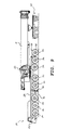
- FIG 4 illustrates the mobile crane 20 with its chassis 22 configured for U.S. road travel.
- the third axle 28 and the sixth axle 34 have been raised, so that they are no longer load bearing.
- the third and sixth axles 28, 34 may be raised by any known suitable mechanism, such as the Megatrak TM suspension system, wherein an hydraulic cylinder with an accumulator acts as a spring. Further, the third and sixth axles 28, 34 may be either steerable or fixed when load bearing.
- the removable rear outrigger 40 of chassis 22 has been removed and replaced with a tag axle assembly 42.
- the middle outrigger 38 could also be removed to further reduce the overall weight of the mobile crane 20.
- the mobile crane 20 can be made to meet the maximum weight restriction for U.S. road travel as well as the axle spacing requirements set by federal, state or local bridge weight regulations.
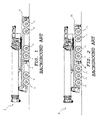
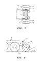
- FIGS 5 and 6 are more detailed top and side view illustrations of the removable rear outrigger 40 attached to a rear end portion 48 of the chassis 22.
- the rear end portion 48 includes first connection features 50.
- the rear outrigger 40 includes second connection features 52 for mating with the first connection features 50.
- the rear outrigger 40 also includes two ground engaging portions 46.
- the boom 21 may be used to lift and install/remove the rear outrigger 40.
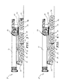
- FIGS 7 and 8 are top and side view illustrations of the removable tag axle assembly 42 attached to the rear end portion 48 of the chassis 22.
- the tag axle assembly 42 includes third connection features 54 for mating with the first connection features 50.
- the third connection features 54 would be similar or identical to the second connection features 52 of the outrigger 40.
- the tag axle assembly 42 also includes a load bearing axle 56 supporting two or more wheels 58.
- the tag axle assembly 42 includes suspension members, and the wheels 58 are non-steerable, steerable, or self-steering, as desired.
- the boom 21 may be used to lift and install/remove the tag axle assembly 42.
- connection features 50, 52, 54 are constructed in accordance with presently available and employed connection features used in conjunction with known removable tag axle assemblies or known removable outriggers. Therefore, the details of the connection features are not particular to the present invention.
- the present invention may be used in combination with any connection features known, so long as the second and third connection features 52, 54 will mate with the first connection features 50, and provide sufficient stability to the tag axle assembly 42 and rear outrigger 40.
- the tag axle assembly 42 may include more than one axle. Such a multiaxle arrangement may be advantageous in further reducing the axle weights. Again, one or more of the axles of the tag axle assembly 42 may be non-steerable, steerable, or self-steering, as desired.
- rear outrigger 40 may be removed and the tag axle assembly 42 installed even when the crane 20 is used in Europe, even though local regulation would not require the configuration.
- the operator/driver might desire this option, especially when the mobile crane 20 is being moved to a job site across European roads which are relatively wide and straight.
- Figure 9 illustrates a configuration of the mobile crane similar to Figure 4 except that the boom 21 is rotated to extend over the rear end portion 48 of the chassis 22, and is attached to and supported by a trailing, wheeled boom dolly 60.
- This configuration spreads the weight of the mobile crane 20 over more axles, thus reducing the load per axle even more than the configuration of Figure 4.
- the spacing of the axle groups, including the axles of the wheeled boom dolly 60 still meets the spacing requirements of the United States bridge weight regulations.
- replacing the removable rear outrigger 40 with the removable tag axle assembly 42 allows a compact crane chassis 22, designed for narrow curvy roads, such as in Europe, to be easily re-configured.
- the chassis 22 can be re-configured for road travel in areas where the horizontal distance between axle groups needs to be increased in order to meet government regulations for traveling on roads or bridges, such as in the United States.
- the suspension system, type of steering and the wheel arrangement for the tag axle assembly may all be modified so that the chassis 22 can be made to meet the regulatory requirements of the area of the world where the mobile crane 20 will be used.
- the above disclosure and drawings have illustrated an easily re-configurable mobile crane 20 having seven axles, such as for a 500 short ton crane.
- the concepts of the present invention can be applied to any crane's carrier, regardless of the number of axles.
- the crane could have fewer or more than seven axles, and axles other than the third and sixth axles could be raised to alter the configuration.
Landscapes
- Engineering & Computer Science (AREA)
- Mechanical Engineering (AREA)
- Health & Medical Sciences (AREA)
- Bioinformatics & Cheminformatics (AREA)
- Cardiology (AREA)
- Heart & Thoracic Surgery (AREA)
- Chemical & Material Sciences (AREA)
- Chemical Kinetics & Catalysis (AREA)
- General Chemical & Material Sciences (AREA)
- Medicinal Chemistry (AREA)
- Nuclear Medicine, Radiotherapy & Molecular Imaging (AREA)
- Organic Chemistry (AREA)
- Pharmacology & Pharmacy (AREA)
- Life Sciences & Earth Sciences (AREA)
- Animal Behavior & Ethology (AREA)
- General Health & Medical Sciences (AREA)
- Public Health (AREA)
- Veterinary Medicine (AREA)
- Jib Cranes (AREA)
- Vehicle Cleaning, Maintenance, Repair, Refitting, And Outriggers (AREA)
Claims (20)
- Mobilkrananordnung mit:einem Chassis (22);ersten Verbindungselementen (50), die an einem Teil (48) des Chassis angeordnet sind;einer Abstützvorrichtung bzw. Outrigger (40) mit wenigstens einem mit dem Boden in Eingriff kommenden Bereich, um mit dem Boden in Eingriff zu kommen, wenn der Mobilkran stationär ist;zweiten Verbindungselementen (52), die an der Abstützvorrichtung zum Paaren mit bzw. zum Anschließen an die ersten Verbindungsmerkmale des Chassis angeordnet sind, um die Abstützvorrichtung abnehmbar an dem Bereich des Chassis zu befestigen;einer Anhängerachseanordnung (tag assembly) (42) mit wenigstens zwei Rädern (58) zum Rollen längs einer Bodenoberfläche; unddritten Verbindungselementen (54), die an der Anhängerachsanordnung zum Paaren mit bzw. zum Anschließen an die ersten Verbindungsmerkmale des Chassis angeordnet sind, um die Anhängerachsanordnung lösbar an dem Bereich des Chassis zu befestigen, wobei die ersten Verbindungselemente entweder die zweiten Verbindungselemente oder die dritten Verbindungselemente in der Weise akzeptieren können, dass der Mobilkran entweder mit der Abstützvorrichtung oder mit der Anhängerachsanordnung verbunden werden kann.
- Mobilkrananordnung nach Anspruch 1, wobei der Bereich des Chassis ein hinterer Endbereich ist, gesehen in der Richtung des normalen Transportes des Mobilkrans.
- Mobilkrananordnung nach Anspruch 1, wobei die Anhängerachsanordnung steuer- bzw. lenkbar ist.
- Mobilkrananordnung nach Anspruch 1, wobei die Anhängerachsanordnung zwei Achsen und wenigstens vier Räder enthält.
- Mobilkrananordnung nach Anspruch 1, wobei die Abstützvorrichtung zwei mit dem Boden in Eingriff kommenden Bereiche enthält.
- Mobilkrananordnung nach Anspruch 5, weiterhin mit:einem Ausleger, der an dem Chassis angebracht ist; undeinem mit Rädern versehenen Ausleger-Anhänger bzw. -"Dolly" zum Haltern des Auslegers beim Transport.
- Mobilkrananordnung nach Anspruch 6, wobei der mit Rädern versehene Ausleger-Dolly lösbar an dem Ausleger befestigt ist.
- Mobilkrananordnung nach Anspruch 1, wobei das Chassis mehrere Achsen enthält, von denen jede mehrere Räder haltert.
- Mobilkrananordnung nach Anspruch 8 mit einer wenigstens einer Achse der Vielzahl von Achsen zugeordneten Anordnung zum selektiven Anheben dieser wenigstens einen Achse, so dass die Räder, die dieser wenigstens einen Achse zugeordnet sind, über die Bodenoberfläche angehoben werden.
- Mobilkrananordnung nach Anspruch 9, wobei der Teil des Chassis ein hinterer Endbereich ist, gesehen in der Richtung des normalen Transportes des Mobilkrans.
- Mobilkrananordnung nach Anspruch 10, wobei die Anhängerachsanordnung eine Achse und wenigstens zwei Räder enthält.
- Mobilkrananordnung nach Anspruch 11, wobei die Abstützvorrichtung zwei mit dem Boden in Eingriff kommende Bereich enthält.
- Mobilkrananordnung nach Anspruch 12, weiterhin mit:einem an dem Chassis angebrachten Ausleger; undeinem mit Rädern versehenen Ausleger-Anhänger bzw. -"Dolly" zum Haltern des Auslegers beim Transport, wobei der mit Rädern versehene Ausleger-Dolly lösbar an dem Ausleger angebracht ist.
- Verfahren zum Betreiben eines Mobilkrans mit den Schritten:Vorsehen eines Mobilkrans mit einem Chassis (22) mit ersten Verbindungselementen (25), die an einem Bereich (48) des Chassis angeordnet ist, und mit einer Abstützvorrichtung bzw. Outrigger (40) mit zweiten Verbindungselementen (52), die an den ersten Verbindungselementen befestigt sind;Vorsehen einer Anhängerachsanordnung (42) (tag axle assembly) mit dritten Verbindungselementen (54);Lösen der zweiten Verbindungselemente von den ersten Verbindungselementen, um die Abstützvorrichtung von dem Teil des Chassis zu entfernen;Befestigen der dritten Verbindungselemente an den ersten Verbindungselementen, um die Anhängerachsanordnung an dem Bereich des Chassis zu befestigen;in Eingriff bringen wenigstens eines Rades der Anhängerachsanordnung mit einer Bodenoberfläche; undFahren des Mobilkrans.
- Verfahren nach Anspruch 14, weiterhin mit den Schritten:Vorsehen mehrerer Achsen an dem Chassis, wobei jede der Achsen mehrere Räder trägt; undAnheben wenigstens einer Achse der mehreren Achsen, sodass die Achsen, die der wenigstens einen Achse zugeordnet sind, über den Boden angehoben werden, wenn die Anhängerachsanordnung an dem Mobilkran befestigt ist.
- Verfahren nach Anspruch 14, weiterhin mit den Schritten:Anhalten des Mobilkrans;Lösen der dritten Verbindungselemente von den ersten Verbindungselementen, um die Anhängerachsanordnung von dem Bereich des Chassis abzunehmen;Befestigen der zweiten Verbindungselemente an den ersten Verbindungselementen, um die Abstützvorrichtung an dem Bereich des Chassis zu befestigen;in Eingriff bringen wenigstens eines den Boden berührenden Bereiches der Abstützvorrichtung mit der Bodenoberfläche; undBetreiben des Krans.
- Verfahren nach Anspruch 14, wobei der Bereich des Chassis der hintere Endbereich ist, gesehen in Richtung des normalen Transportes des Mobilkrans.
- Verfahren nach Anspruch 17, weiterhin mit den Schritten:Vorsehen eines Auslegers, der an dem Chassis befestigt ist, und Vorsehen eines mit Rädern versehenen Ausleger-Anhängers bzw. -"Dollys";Befestigen des mit Rädern versehenen Ausleger-Dollys an dem Ausleger; undHaltern des Auslegers auf dem Ausleger-Dolly, wenn der Mobilkran fährt.
- Verfahren nach Anspruch 14, weiterhin mit den Schritten:Vorsehen eines an dem Chassis befestigten Auslegers und Vorsehen eines mit Rädern versehenen Ausleger-Anhängers bzw. -"Dollys"; undHaltern des Auslegers an dem Ausleger-Dolly, wenn der Mobilkran fährt.
- Verfahren nach Anspruch 19, weiterhin mit dem Schritt:Befestigen des mit Rädern versehenen Ausleger-Dolly an dem Ausleger.
Applications Claiming Priority (2)
| Application Number | Priority Date | Filing Date | Title |
|---|---|---|---|
| US09/666,599 US6631817B1 (en) | 2000-09-20 | 2000-09-20 | Re-configurable crane carrier |
| US666599 | 2000-09-20 |
Publications (3)
| Publication Number | Publication Date |
|---|---|
| EP1190979A2 EP1190979A2 (de) | 2002-03-27 |
| EP1190979A3 EP1190979A3 (de) | 2003-01-02 |
| EP1190979B1 true EP1190979B1 (de) | 2004-08-18 |
Family
ID=24674681
Family Applications (1)
| Application Number | Title | Priority Date | Filing Date |
|---|---|---|---|
| EP01121709A Expired - Lifetime EP1190979B1 (de) | 2000-09-20 | 2001-09-17 | Rekonfigurierbarer Krantrager |
Country Status (9)
| Country | Link |
|---|---|
| US (1) | US6631817B1 (de) |
| EP (1) | EP1190979B1 (de) |
| JP (2) | JP2002154787A (de) |
| CN (1) | CN1221463C (de) |
| AU (1) | AU782236B2 (de) |
| CA (1) | CA2357445C (de) |
| DE (1) | DE60104955T2 (de) |
| ES (1) | ES2227033T3 (de) |
| RU (1) | RU2271987C2 (de) |
Families Citing this family (15)
| Publication number | Priority date | Publication date | Assignee | Title |
|---|---|---|---|---|
| DE10231911A1 (de) * | 2002-07-09 | 2004-02-05 | Gottwald Port Technology Gmbh | Hafenmobilkran als mobiles Umschlaggerät für Stückgüter |
| DE10328770A1 (de) * | 2003-06-25 | 2005-01-27 | Putzmeister Ag | Fahrbare Betonpumpe mit Verteilermast |
| DE10328767A1 (de) * | 2003-06-25 | 2005-01-20 | Putzmeister Ag | Fahrbare Betonpumpe mit Verteilermast |
| US7841604B2 (en) | 2008-06-26 | 2010-11-30 | Jack W Mitchell | Detachable trailing tag axle |
| DE202010002947U1 (de) * | 2010-03-01 | 2011-08-01 | Liebherr-Werk Ehingen Gmbh | Fahrzeugkran |
| DE102010023275B4 (de) * | 2010-06-10 | 2022-05-12 | Liebherr-Werk Ehingen Gmbh | Verfahren zum Verfahren von Großkranen im aufgerüsteten System und System zum Durchführen dieses Verfahrens |
| DE102015205008A1 (de) * | 2015-03-19 | 2016-09-22 | Terex Global Gmbh | Unterwagen für einen Fahrzeugkran sowie Fahrzeugkran mit einem derartigen Unterwagen |
| US9919637B1 (en) * | 2016-06-22 | 2018-03-20 | Robert Dennis Dieleman | Apparatus and system for transporting and operating a crane and method of use |
| WO2018049475A1 (en) * | 2016-09-15 | 2018-03-22 | Terex Australia Pty Ltd | Crane counterweight and suspension |
| DE102017003730B4 (de) * | 2017-04-18 | 2020-08-20 | Liebherr-Werk Ehingen Gmbh | Fahrzeugrahmen für einen Mobilkran sowie Mobilkran |
| CN107416173A (zh) * | 2017-06-13 | 2017-12-01 | 中国电子科技集团公司第三十八研究所 | 一种机动式一体化锚泊底盘 |
| CN108275160A (zh) * | 2017-12-27 | 2018-07-13 | 湖北华舟重工应急装备股份有限公司 | 铁路临时站台移动架设机构 |
| RU2674214C1 (ru) * | 2018-02-15 | 2018-12-05 | Борис Васильевич Кузнецов | Автокран |
| DE102019201049B3 (de) * | 2019-01-28 | 2020-06-18 | Tadano Faun Gmbh | Mobilkran, Mobilkran-Dolly und Mobilkransystem |
| DE102021102844B3 (de) | 2021-02-08 | 2022-07-21 | Manitowoc Crane Group France Sas | Mobilkran-Fahrzeugrahmen mit lösbar miteinander verbindbaren Rahmenteilen |
Family Cites Families (28)
| Publication number | Priority date | Publication date | Assignee | Title |
|---|---|---|---|---|
| US2518410A (en) | 1948-05-18 | 1950-08-08 | Gulf Lumber Company Inc | Attachment for carrying a trailer on a truck |
| US3184076A (en) | 1963-05-23 | 1965-05-18 | Baldwin Lima Hamilton Corp | Auxiliary axle for vehicles |
| DE1231867B (de) | 1965-04-29 | 1967-01-05 | Beteiligungs & Patentverw Gmbh | Schwerlast-Autokran |
| FR1494349A (fr) * | 1966-07-19 | 1967-09-08 | Potain & Cie Ets F | Perfectionnements aux châssis de grues à tour remorquables |
| US3578352A (en) * | 1968-02-16 | 1971-05-11 | Krupp Gmbh | Vehicle with frame adapted to be raised and lowered |
| US3747957A (en) | 1971-04-29 | 1973-07-24 | Koehring Co | Crane boom load transfer dolly |
| US3836012A (en) | 1973-07-09 | 1974-09-17 | Bucyrus Erie Co | Removable outrigger assembly with rotatable jack |
| US3926453A (en) * | 1974-08-30 | 1975-12-16 | Pierce Pacific Mfg Inc | Carrier vehicle with pusher-type dolly |
| FI51932C (fi) | 1976-05-06 | 1977-05-10 | Rauma Repola Oy | Menetelmä nosturin tukielementin asentamisessa. |
| US4199298A (en) | 1977-12-05 | 1980-04-22 | Tbw Industries, Inc. | Trailer for skid mounted tanks |
| DE2837398A1 (de) * | 1978-08-26 | 1980-03-06 | Gottwald Kg Leo | Fahrzeugkran |
| US4273244A (en) | 1979-01-29 | 1981-06-16 | Fmc Corporation | Crane upperstructure self-transferring system |
| JPS55106843A (en) * | 1979-02-13 | 1980-08-16 | Kobe Steel Ltd | Movable crane |
| JPS5730608A (en) * | 1980-07-29 | 1982-02-18 | Toru Ito | Device for lifting a part of wheel above road surface during running of empty car |
| US4363412A (en) | 1980-08-14 | 1982-12-14 | Kidde, Inc. | Crane counterweight and handling method |
| DE3139596A1 (de) | 1981-10-05 | 1983-04-21 | Liebherr-Werk Ehingen Gmbh, 7930 Ehingen | Schwerlast-teleskopkran |
| US4434994A (en) | 1982-04-28 | 1984-03-06 | Pepin Julien H | Boom axle |
| JPS59109409A (ja) * | 1982-12-13 | 1984-06-25 | Kobe Steel Ltd | 大型車両の4軸懸架装置 |
| US4664411A (en) | 1983-09-26 | 1987-05-12 | Kidde, Inc. | Method of and apparatus for removal and installation of outrigger box on cranes |
| JPS60191508U (ja) * | 1984-05-30 | 1985-12-19 | 日産ディーゼル工業株式会社 | 前二軸車両の車軸リフトアツプ装置 |
| US4640421A (en) | 1985-02-26 | 1987-02-03 | Mason Daniel P | Truck crane conversion to crawler crane |
| JPS61152066U (de) * | 1985-03-06 | 1986-09-19 | ||
| US5110149A (en) | 1987-11-30 | 1992-05-05 | Dahlstrom Gale E | Trailer system design for enhanced load-carrying capacity and maneuverability |
| US5018630A (en) * | 1988-11-21 | 1991-05-28 | Mcghie James R | High-capacity lift crane assembly |
| US5029895A (en) | 1989-07-11 | 1991-07-09 | Schwing America, Inc. | Outrigger-mounted axle assembly |
| US5348171A (en) | 1992-12-08 | 1994-09-20 | Link-Belt Construction Equip. Co. | Removable outrigger for mobile crane |
| JPH0948252A (ja) * | 1995-08-04 | 1997-02-18 | Kato Works Co Ltd | ホイールクレーン |
| DE19728822B4 (de) * | 1997-07-05 | 2007-07-05 | Hackenfort, Günter, Dipl.-Ing. | Anbaunachlauffahrwerk |
-
2000
- 2000-09-20 US US09/666,599 patent/US6631817B1/en not_active Expired - Lifetime
-
2001
- 2001-09-17 EP EP01121709A patent/EP1190979B1/de not_active Expired - Lifetime
- 2001-09-17 ES ES01121709T patent/ES2227033T3/es not_active Expired - Lifetime
- 2001-09-17 DE DE60104955T patent/DE60104955T2/de not_active Expired - Lifetime
- 2001-09-17 AU AU72145/01A patent/AU782236B2/en not_active Ceased
- 2001-09-18 CA CA002357445A patent/CA2357445C/en not_active Expired - Fee Related
- 2001-09-20 CN CNB011406747A patent/CN1221463C/zh not_active Expired - Fee Related
- 2001-09-20 JP JP2001287094A patent/JP2002154787A/ja active Pending
- 2001-09-20 RU RU2001125703/11A patent/RU2271987C2/ru not_active IP Right Cessation
-
2007
- 2007-04-09 JP JP2007101387A patent/JP5155587B2/ja not_active Expired - Fee Related
Also Published As
| Publication number | Publication date |
|---|---|
| CA2357445C (en) | 2007-12-04 |
| DE60104955D1 (de) | 2004-09-23 |
| AU7214501A (en) | 2002-03-21 |
| CN1221463C (zh) | 2005-10-05 |
| DE60104955T2 (de) | 2005-08-11 |
| US6631817B1 (en) | 2003-10-14 |
| JP2007191315A (ja) | 2007-08-02 |
| EP1190979A3 (de) | 2003-01-02 |
| RU2271987C2 (ru) | 2006-03-20 |
| CN1344668A (zh) | 2002-04-17 |
| JP5155587B2 (ja) | 2013-03-06 |
| CA2357445A1 (en) | 2002-03-20 |
| ES2227033T3 (es) | 2005-04-01 |
| JP2002154787A (ja) | 2002-05-28 |
| AU782236B2 (en) | 2005-07-14 |
| EP1190979A2 (de) | 2002-03-27 |
Similar Documents
| Publication | Publication Date | Title |
|---|---|---|
| JP5155587B2 (ja) | 再構成可能なクレーンキャリア | |
| US20040256344A1 (en) | Traveling crane | |
| US6516961B1 (en) | Ringlift crane | |
| US20040165977A1 (en) | Deck for a service vehicle | |
| US6341705B1 (en) | Crane vehicle | |
| US6158602A (en) | Railwheel system for supporting loads on a road-traveling gantry crane | |
| US20170066632A1 (en) | Port crane | |
| US4492389A (en) | High-lift hydraulic axle | |
| US4117901A (en) | Self-propelled articulated vehicle | |
| US6360905B1 (en) | Crawler-mounted crane with detachable lateral stablizers | |
| CN107839896A (zh) | 一种机场物资装卸平台底盘 | |
| RU2001125703A (ru) | Комплект частей и способ эксплуатации самоходного крана | |
| CN214493090U (zh) | 一种模拟飞机加载车用车架系统 | |
| US4723667A (en) | Chassis of a heavy road vehicle particularly a multiaxle mobile crane | |
| US7159888B1 (en) | Modular transport vehicle and method of use | |
| CA2235847C (en) | Vehicle for handling various materials or operating units in sheds, airports, markets and the like | |
| CN112208636A (zh) | 一种可独立转向的多轴挂车 | |
| EP1773645B1 (de) | Passiv lenkbare modulachse | |
| ATE238225T1 (de) | Fahrwerk für eine weitausladende arbeitsvorrichtung, insbesondere für einen bauhochkran | |
| CN213035892U (zh) | 一种摆动桥加固结构、底盘总成及工程车 | |
| CN212532081U (zh) | 一种可变幅的手拉副臂 | |
| CN214028834U (zh) | 一种可独立转向的多轴挂车 | |
| US20060021263A1 (en) | Mobile excavator | |
| CN219406689U (zh) | 一种皮带输送车底盘 | |
| EP0223761A1 (de) | Fahrbares Hebezeug |
Legal Events
| Date | Code | Title | Description |
|---|---|---|---|
| PUAI | Public reference made under article 153(3) epc to a published international application that has entered the european phase |
Free format text: ORIGINAL CODE: 0009012 |
|
| AK | Designated contracting states |
Kind code of ref document: A2 Designated state(s): AT BE CH CY DE DK ES FI FR GB GR IE IT LI LU MC NL PT SE TR |
|
| AX | Request for extension of the european patent |
Free format text: AL;LT;LV;MK;RO;SI |
|
| PUAL | Search report despatched |
Free format text: ORIGINAL CODE: 0009013 |
|
| AK | Designated contracting states |
Kind code of ref document: A3 Designated state(s): AT BE CH CY DE DK ES FI FR GB GR IE IT LI LU MC NL PT SE TR |
|
| AX | Request for extension of the european patent |
Free format text: AL;LT;LV;MK;RO;SI |
|
| RIC1 | Information provided on ipc code assigned before grant |
Free format text: 7B 66C 23/32 A, 7B 66C 23/62 B, 7B 66C 23/78 B, 7B 66C 23/42 B |
|
| 17P | Request for examination filed |
Effective date: 20030319 |
|
| AKX | Designation fees paid |
Designated state(s): DE ES FR GB IT NL |
|
| GRAP | Despatch of communication of intention to grant a patent |
Free format text: ORIGINAL CODE: EPIDOSNIGR1 |
|
| GRAS | Grant fee paid |
Free format text: ORIGINAL CODE: EPIDOSNIGR3 |
|
| GRAA | (expected) grant |
Free format text: ORIGINAL CODE: 0009210 |
|
| AK | Designated contracting states |
Kind code of ref document: B1 Designated state(s): DE ES FR GB IT NL |
|
| REG | Reference to a national code |
Ref country code: GB Ref legal event code: FG4D |
|
| REG | Reference to a national code |
Ref country code: IE Ref legal event code: FG4D |
|
| REF | Corresponds to: |
Ref document number: 60104955 Country of ref document: DE Date of ref document: 20040923 Kind code of ref document: P |
|
| REG | Reference to a national code |
Ref country code: ES Ref legal event code: FG2A Ref document number: 2227033 Country of ref document: ES Kind code of ref document: T3 |
|
| PLBE | No opposition filed within time limit |
Free format text: ORIGINAL CODE: 0009261 |
|
| STAA | Information on the status of an ep patent application or granted ep patent |
Free format text: STATUS: NO OPPOSITION FILED WITHIN TIME LIMIT |
|
| ET | Fr: translation filed | ||
| 26N | No opposition filed |
Effective date: 20050519 |
|
| REG | Reference to a national code |
Ref country code: FR Ref legal event code: PLFP Year of fee payment: 16 |
|
| PGFP | Annual fee paid to national office [announced via postgrant information from national office to epo] |
Ref country code: IT Payment date: 20160921 Year of fee payment: 16 Ref country code: NL Payment date: 20160913 Year of fee payment: 16 Ref country code: GB Payment date: 20160914 Year of fee payment: 16 Ref country code: DE Payment date: 20160913 Year of fee payment: 16 |
|
| PGFP | Annual fee paid to national office [announced via postgrant information from national office to epo] |
Ref country code: FR Payment date: 20160816 Year of fee payment: 16 |
|
| PGFP | Annual fee paid to national office [announced via postgrant information from national office to epo] |
Ref country code: ES Payment date: 20160810 Year of fee payment: 16 |
|
| REG | Reference to a national code |
Ref country code: DE Ref legal event code: R119 Ref document number: 60104955 Country of ref document: DE |
|
| REG | Reference to a national code |
Ref country code: NL Ref legal event code: MM Effective date: 20171001 |
|
| GBPC | Gb: european patent ceased through non-payment of renewal fee |
Effective date: 20170917 |
|
| PG25 | Lapsed in a contracting state [announced via postgrant information from national office to epo] |
Ref country code: NL Free format text: LAPSE BECAUSE OF NON-PAYMENT OF DUE FEES Effective date: 20171001 |
|
| REG | Reference to a national code |
Ref country code: FR Ref legal event code: ST Effective date: 20180531 |
|
| PG25 | Lapsed in a contracting state [announced via postgrant information from national office to epo] |
Ref country code: GB Free format text: LAPSE BECAUSE OF NON-PAYMENT OF DUE FEES Effective date: 20170917 Ref country code: DE Free format text: LAPSE BECAUSE OF NON-PAYMENT OF DUE FEES Effective date: 20180404 |
|
| PG25 | Lapsed in a contracting state [announced via postgrant information from national office to epo] |
Ref country code: FR Free format text: LAPSE BECAUSE OF NON-PAYMENT OF DUE FEES Effective date: 20171002 Ref country code: IT Free format text: LAPSE BECAUSE OF NON-PAYMENT OF DUE FEES Effective date: 20170917 |
|
| REG | Reference to a national code |
Ref country code: ES Ref legal event code: FD2A Effective date: 20181019 |
|
| PG25 | Lapsed in a contracting state [announced via postgrant information from national office to epo] |
Ref country code: ES Free format text: LAPSE BECAUSE OF NON-PAYMENT OF DUE FEES Effective date: 20170918 |