EP1188534A2 - Article décoré moulé par injection, et son procédé de fabrication - Google Patents
Article décoré moulé par injection, et son procédé de fabrication Download PDFInfo
- Publication number
- EP1188534A2 EP1188534A2 EP01660155A EP01660155A EP1188534A2 EP 1188534 A2 EP1188534 A2 EP 1188534A2 EP 01660155 A EP01660155 A EP 01660155A EP 01660155 A EP01660155 A EP 01660155A EP 1188534 A2 EP1188534 A2 EP 1188534A2
- Authority
- EP
- European Patent Office
- Prior art keywords
- injection moulded
- foil
- layer
- moulded layer
- injection
- Prior art date
- Legal status (The legal status is an assumption and is not a legal conclusion. Google has not performed a legal analysis and makes no representation as to the accuracy of the status listed.)
- Granted
Links
Images


Classifications
-
- B—PERFORMING OPERATIONS; TRANSPORTING
- B29—WORKING OF PLASTICS; WORKING OF SUBSTANCES IN A PLASTIC STATE IN GENERAL
- B29C—SHAPING OR JOINING OF PLASTICS; SHAPING OF MATERIAL IN A PLASTIC STATE, NOT OTHERWISE PROVIDED FOR; AFTER-TREATMENT OF THE SHAPED PRODUCTS, e.g. REPAIRING
- B29C45/00—Injection moulding, i.e. forcing the required volume of moulding material through a nozzle into a closed mould; Apparatus therefor
- B29C45/16—Making multilayered or multicoloured articles
- B29C45/1671—Making multilayered or multicoloured articles with an insert
-
- B—PERFORMING OPERATIONS; TRANSPORTING
- B29—WORKING OF PLASTICS; WORKING OF SUBSTANCES IN A PLASTIC STATE IN GENERAL
- B29C—SHAPING OR JOINING OF PLASTICS; SHAPING OF MATERIAL IN A PLASTIC STATE, NOT OTHERWISE PROVIDED FOR; AFTER-TREATMENT OF THE SHAPED PRODUCTS, e.g. REPAIRING
- B29C45/00—Injection moulding, i.e. forcing the required volume of moulding material through a nozzle into a closed mould; Apparatus therefor
- B29C45/14—Injection moulding, i.e. forcing the required volume of moulding material through a nozzle into a closed mould; Apparatus therefor incorporating preformed parts or layers, e.g. injection moulding around inserts or for coating articles
- B29C45/14688—Coating articles provided with a decoration
-
- B—PERFORMING OPERATIONS; TRANSPORTING
- B29—WORKING OF PLASTICS; WORKING OF SUBSTANCES IN A PLASTIC STATE IN GENERAL
- B29C—SHAPING OR JOINING OF PLASTICS; SHAPING OF MATERIAL IN A PLASTIC STATE, NOT OTHERWISE PROVIDED FOR; AFTER-TREATMENT OF THE SHAPED PRODUCTS, e.g. REPAIRING
- B29C45/00—Injection moulding, i.e. forcing the required volume of moulding material through a nozzle into a closed mould; Apparatus therefor
- B29C45/14—Injection moulding, i.e. forcing the required volume of moulding material through a nozzle into a closed mould; Apparatus therefor incorporating preformed parts or layers, e.g. injection moulding around inserts or for coating articles
- B29C45/14778—Injection moulding, i.e. forcing the required volume of moulding material through a nozzle into a closed mould; Apparatus therefor incorporating preformed parts or layers, e.g. injection moulding around inserts or for coating articles the article consisting of a material with particular properties, e.g. porous, brittle
- B29C45/14811—Multilayered articles
-
- B—PERFORMING OPERATIONS; TRANSPORTING
- B29—WORKING OF PLASTICS; WORKING OF SUBSTANCES IN A PLASTIC STATE IN GENERAL
- B29C—SHAPING OR JOINING OF PLASTICS; SHAPING OF MATERIAL IN A PLASTIC STATE, NOT OTHERWISE PROVIDED FOR; AFTER-TREATMENT OF THE SHAPED PRODUCTS, e.g. REPAIRING
- B29C45/00—Injection moulding, i.e. forcing the required volume of moulding material through a nozzle into a closed mould; Apparatus therefor
- B29C45/14—Injection moulding, i.e. forcing the required volume of moulding material through a nozzle into a closed mould; Apparatus therefor incorporating preformed parts or layers, e.g. injection moulding around inserts or for coating articles
- B29C45/14688—Coating articles provided with a decoration
- B29C2045/14696—Coating articles provided with a decoration transparent decorated inserts
-
- B—PERFORMING OPERATIONS; TRANSPORTING
- B29—WORKING OF PLASTICS; WORKING OF SUBSTANCES IN A PLASTIC STATE IN GENERAL
- B29C—SHAPING OR JOINING OF PLASTICS; SHAPING OF MATERIAL IN A PLASTIC STATE, NOT OTHERWISE PROVIDED FOR; AFTER-TREATMENT OF THE SHAPED PRODUCTS, e.g. REPAIRING
- B29C45/00—Injection moulding, i.e. forcing the required volume of moulding material through a nozzle into a closed mould; Apparatus therefor
- B29C45/14—Injection moulding, i.e. forcing the required volume of moulding material through a nozzle into a closed mould; Apparatus therefor incorporating preformed parts or layers, e.g. injection moulding around inserts or for coating articles
- B29C45/14688—Coating articles provided with a decoration
- B29C2045/14713—Coating articles provided with a decoration decorations in contact with injected material
-
- B—PERFORMING OPERATIONS; TRANSPORTING
- B29—WORKING OF PLASTICS; WORKING OF SUBSTANCES IN A PLASTIC STATE IN GENERAL
- B29C—SHAPING OR JOINING OF PLASTICS; SHAPING OF MATERIAL IN A PLASTIC STATE, NOT OTHERWISE PROVIDED FOR; AFTER-TREATMENT OF THE SHAPED PRODUCTS, e.g. REPAIRING
- B29C45/00—Injection moulding, i.e. forcing the required volume of moulding material through a nozzle into a closed mould; Apparatus therefor
- B29C45/14—Injection moulding, i.e. forcing the required volume of moulding material through a nozzle into a closed mould; Apparatus therefor incorporating preformed parts or layers, e.g. injection moulding around inserts or for coating articles
- B29C45/14688—Coating articles provided with a decoration
- B29C2045/14737—Coating articles provided with a decoration decorations printed on the insert by a digital imaging technique
-
- B—PERFORMING OPERATIONS; TRANSPORTING
- B29—WORKING OF PLASTICS; WORKING OF SUBSTANCES IN A PLASTIC STATE IN GENERAL
- B29C—SHAPING OR JOINING OF PLASTICS; SHAPING OF MATERIAL IN A PLASTIC STATE, NOT OTHERWISE PROVIDED FOR; AFTER-TREATMENT OF THE SHAPED PRODUCTS, e.g. REPAIRING
- B29C45/00—Injection moulding, i.e. forcing the required volume of moulding material through a nozzle into a closed mould; Apparatus therefor
- B29C45/16—Making multilayered or multicoloured articles
- B29C45/1671—Making multilayered or multicoloured articles with an insert
- B29C2045/1673—Making multilayered or multicoloured articles with an insert injecting the first layer, then feeding the insert, then injecting the second layer
-
- B—PERFORMING OPERATIONS; TRANSPORTING
- B29—WORKING OF PLASTICS; WORKING OF SUBSTANCES IN A PLASTIC STATE IN GENERAL
- B29K—INDEXING SCHEME ASSOCIATED WITH SUBCLASSES B29B, B29C OR B29D, RELATING TO MOULDING MATERIALS OR TO MATERIALS FOR MOULDS, REINFORCEMENTS, FILLERS OR PREFORMED PARTS, e.g. INSERTS
- B29K2995/00—Properties of moulding materials, reinforcements, fillers, preformed parts or moulds
- B29K2995/0018—Properties of moulding materials, reinforcements, fillers, preformed parts or moulds having particular optical properties, e.g. fluorescent or phosphorescent
- B29K2995/002—Coloured
-
- B—PERFORMING OPERATIONS; TRANSPORTING
- B29—WORKING OF PLASTICS; WORKING OF SUBSTANCES IN A PLASTIC STATE IN GENERAL
- B29L—INDEXING SCHEME ASSOCIATED WITH SUBCLASS B29C, RELATING TO PARTICULAR ARTICLES
- B29L2031/00—Other particular articles
- B29L2031/34—Electrical apparatus, e.g. sparking plugs or parts thereof
- B29L2031/3431—Telephones, Earphones
- B29L2031/3437—Cellular phones
-
- Y—GENERAL TAGGING OF NEW TECHNOLOGICAL DEVELOPMENTS; GENERAL TAGGING OF CROSS-SECTIONAL TECHNOLOGIES SPANNING OVER SEVERAL SECTIONS OF THE IPC; TECHNICAL SUBJECTS COVERED BY FORMER USPC CROSS-REFERENCE ART COLLECTIONS [XRACs] AND DIGESTS
- Y10—TECHNICAL SUBJECTS COVERED BY FORMER USPC
- Y10T—TECHNICAL SUBJECTS COVERED BY FORMER US CLASSIFICATION
- Y10T428/00—Stock material or miscellaneous articles
- Y10T428/24—Structurally defined web or sheet [e.g., overall dimension, etc.]
- Y10T428/24479—Structurally defined web or sheet [e.g., overall dimension, etc.] including variation in thickness
- Y10T428/24612—Composite web or sheet
-
- Y—GENERAL TAGGING OF NEW TECHNOLOGICAL DEVELOPMENTS; GENERAL TAGGING OF CROSS-SECTIONAL TECHNOLOGIES SPANNING OVER SEVERAL SECTIONS OF THE IPC; TECHNICAL SUBJECTS COVERED BY FORMER USPC CROSS-REFERENCE ART COLLECTIONS [XRACs] AND DIGESTS
- Y10—TECHNICAL SUBJECTS COVERED BY FORMER USPC
- Y10T—TECHNICAL SUBJECTS COVERED BY FORMER US CLASSIFICATION
- Y10T428/00—Stock material or miscellaneous articles
- Y10T428/24—Structurally defined web or sheet [e.g., overall dimension, etc.]
- Y10T428/24802—Discontinuous or differential coating, impregnation or bond [e.g., artwork, printing, retouched photograph, etc.]
- Y10T428/24917—Discontinuous or differential coating, impregnation or bond [e.g., artwork, printing, retouched photograph, etc.] including metal layer
-
- Y—GENERAL TAGGING OF NEW TECHNOLOGICAL DEVELOPMENTS; GENERAL TAGGING OF CROSS-SECTIONAL TECHNOLOGIES SPANNING OVER SEVERAL SECTIONS OF THE IPC; TECHNICAL SUBJECTS COVERED BY FORMER USPC CROSS-REFERENCE ART COLLECTIONS [XRACs] AND DIGESTS
- Y10—TECHNICAL SUBJECTS COVERED BY FORMER USPC
- Y10T—TECHNICAL SUBJECTS COVERED BY FORMER US CLASSIFICATION
- Y10T428/00—Stock material or miscellaneous articles
- Y10T428/25—Web or sheet containing structurally defined element or component and including a second component containing structurally defined particles
-
- Y—GENERAL TAGGING OF NEW TECHNOLOGICAL DEVELOPMENTS; GENERAL TAGGING OF CROSS-SECTIONAL TECHNOLOGIES SPANNING OVER SEVERAL SECTIONS OF THE IPC; TECHNICAL SUBJECTS COVERED BY FORMER USPC CROSS-REFERENCE ART COLLECTIONS [XRACs] AND DIGESTS
- Y10—TECHNICAL SUBJECTS COVERED BY FORMER USPC
- Y10T—TECHNICAL SUBJECTS COVERED BY FORMER US CLASSIFICATION
- Y10T428/00—Stock material or miscellaneous articles
- Y10T428/31504—Composite [nonstructural laminate]
- Y10T428/31678—Of metal
Definitions
- the invention concerns generally the technology of producing injection moulded products. Especially the invention concerns the technology of producing such products that have certain features that originate from an in-mould decorating process.
- Injection moulding refers to the procedure of manufacturing products by injecting molten plastic material into a carefully designed mould that defines a cavity having the form of the desired end product.
- In-mould decorating may be generally understood to denote any technology, which applies text, pattern or image to a moulding as a part of the moulding process.
- in-mould decorating refers to a process where a decorative insert is placed into a mould before injecting molten plastic material into the mould.
- the word "decorative" should be understood widely, because in addition to purely aesthetic purposes the insert and/or the graphic objects carried by it may have e.g. informative or protective functions.
- thermoformable foil the base material of which is typically polycarbonate or an alloy thereof.
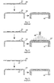
- Fig. 1 is a cross-sectional diagram that illustrates certain phases of a very simple in-mould decorating process. Patterns 101 are first formed onto the surface of a foil 102 through screen printing or other suitable pattern-forming process. The patterned foil 102 is formed to make it conform to the three-dimensional form of the mould, which (mould) itself is not shown in fig. 1.
- Several alternative methods are known for executing the forming step, such as vacuum or thermoforming, pressure assisted vacuum forming or the high pressure forming technology developed by the German companies Bayer and Niebling HDVF.
- the piece of foil 102 belonging to a single workpiece is cut and trimmed to size, transferred to the moulding operation as well as positioned and secured into the mould.
- the plastic material is then injected into the mould so that it fuses onto the back of the foil 102 to form the bulk of the end product 103.
- the relative thicknessesof the foil 102 and patterns 101 are greatly exaggerated in all drawings for the sake of graphical clarity.
- the decorative patterns 101 are clearly visible because they form the topmost layer on the surface of the product.
- Fig. 2 illustrates how a protective coating 201 can be applied onto the outmost surface of the product e.g. by spraying it through a nozzle 202.
- a protective coating 201 can be applied onto the outmost surface of the product e.g. by spraying it through a nozzle 202.
- Many protective lacquers comprise easily evaporated solvents that are potential sources for fire and environment hazards in the manufacturing plant, which makes their use unattractive.
- the use of a separate coating layer makes the manufacturing process also more vulnerable to dust and other impurities in air.
- Fig. 3 illustrates another solution to the problems concerning the mechanical stability of the decoration.
- a transparent foil 102 is used as the carrier of the decorative patterns 101, which are printed onto the inner surface (so-called second surface) of the foil instead of its outer surface like in figs. 1 and 2.
- the patterns 101 become sandwiched between the transparent foil 102 and the plastic body part 103 so that the former protects the patterns against external factors.
- This approach involves also certain difficulties that are mainly related to the patterns' poor resistance against the erosion caused by the hot, molten polymer resin that flows into the mould and along the printed surface of the foil.
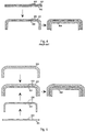
- Fig. 4 illustrates a double foil solution where instead of a single foil a laminated structure of two parallel foils 401 and 402 is used.
- the patterns 403 are formed on either the lower surface of the upper foil 401 or the upper surface of the lower foil 402 so that in the laminated foil structure they are enclosed in between the foils.
- the laminated structure is formed, cut and trimmed into size just as if it was a single foil in some of the above-described methods, after which it is places into the mould and the plastic bulk part 404 is injection moulded onto its inner surface.
- Using two parallel foils and laminating them together has, however, proven to be somewhat problematic because the foil structure tends in some cases to become visible on the surface of the completed product. Additionally the process becomes rather complex and involves a relatively large number of processing steps.
- the objects of the invention are achieved by providing an injection moulded layer on the outside of the decorated foil that constitutes the insert in the injection moulding process, either by injection moulding on top of the foil or by injection moulding the product in concern in at least two injection moulded layers so that the decorative patterns and their carrier foil are inserted between said layers before injection moulding the latter one of them.
- the invention applies to an injection moulded product comprising:
- the invention applies also to a method for manufacturing an injection moulded product, comprising the steps of:
- An injection moulded plastic layer at the outmost surface of an injection moulded product offers excellent resistance against frictional wear and damages that result from external impacts, at least when compared to the modest durability of an insert foil made of polycarbonate. If the outmost layer is additionally at least partly transparent to electromagnetic radiation at the wavelengths of visible light, decorations or other patterns that are inside it can be observed from the outside. A further injection moulded plastic layer beneath the patterns may serve a multitude of purposes ranging from structural enforcement to providing depth to the visual appearance of the decoration.
- the (at least partly) transparent outmost layer is injection moulded first, without placing the decorative insert meant by the invention into the mould yet at this stage.
- the preformed insert is then placed against the inner surface of the already injection moulded transparent layer, and another layer of plastics is injection moulded onto the inner surface of the structure thus formed so that in the final product the insert remains between the injection moulded layers.
- the invention does not preclude the use of multilayered laminated inserts where patterns may come on multiple surfaces but where the inner surface of the innermost layer is non-printed to that said innermost layer acts as a protective layer. Even having patterns on the surface which comes against the second-step injection moulded layed is not completely excluded, provided that the problem of stability against flowing molten polymer resin can be solved e.g. by using some specific ink that has the required durability.
- the decorative insert is produced first and placed into the injection mould against the core or kernel of the mould.
- the (at least partly) transparent outmost layer is then injection moulded on top of the foil, where the direction-related term "on top” means that the injection moulded layer becomes the intended outer surface of the final product.
- the invention can be used for many other purposes.
- the "decorative" pattern that is, as a result of using at least the first aspect of the invention, truly enclosed within the bulk material of an injection molded product is very well protected against unauthorised tampering, which means that a suitably designed pattern may serve as some kind of an authenticity certificate of the product.
- the pattern may have specific characteristics that are only observable under ultraviolet light or some other exceptional environmental conditions. If parts of an apparatus, which is located within an injection moulded cover, should be constantly available for visual observation while other parts should be hidden, a pattern layer may be used to keep the parts of the latter kind out of sight. If the "decorative" pattern layer is electrically conductive, it can even be used as a part of the electromagnetic shielding of the inner components.
- the bulk of the injection moulded layer(s) may be used to play a role in the decorative effect.
- colouring agents, metallic flakes or fluorescent or phosphorescent dyes can be mixed into the polymer resin so that they give the injection moulded part(s) a certain advantageous visual appearance.
- the outmost layer is much better visible than the inner layer(s)
- its material and properties can be optimised for good visual properties.
- the innermost layer need not be visible to the user at all, or at least it is much less visible than the outermost layer. Therefore its material and properties can be optimised for some other factors like structural stiffness and/or ease of adapting its inside for the mechanical attachment of the inner parts of the device.
- a foil 501 is provided as the carrier of decorative patterns 502.
- decorative patterns 502. Both the term “decorative” and the term “patterns” should be understood broadly, because the graphical objects carried by the foil 501 can serve a multitude of purposes in addition to being just aesthetically decorative, and they may include various object types including bot not being limited to lines and two-dimensional shapes, bitmaps, hues and background colours, alphanumerical characters, photographic imagery and areas possessing various degrees of reflectivity or transparency.
- Any types of foils that are known to be applicable to in-mould decorating can be used as the foil 501; typically the foil consists of one or several layers of polycarbonate film.
- the foil 501 itself may have some basic (opaque or translucent) colour or it may be completely transparent. It may even consist of several differently coloured areas or patches.
- the foil 501 does not need to be continuous, although a certain degree of continuity is advantageous in terms of automated mass production.
- the foil 501 may comprise openings therethrough.
- a first injection moulded part 503 is also provided.
- This part is to constitute an outer layer of the end product, and according to the invention it is at least partly transparent or translucent to visible light.
- the first injection moulded part 503 we denote the first injection moulded part 503 as the outer layer for short.
- the outer layer 503 may have some basic (opaque or translucent) colour or it may be completely transparent. It may even consist of several differently coloured areas or patches, and effect materials such as metal flakes or dyes can be mixed to the polymer resin from which the outer layer 503 is injection moulded in order to give it a specific appearance.
- the effect materials may have dynamically changing properties such as a changing tone according to ultraviolet radiation incident on the material or phosphorescent or fluorescent glow in the dark.
- the outer layer 503 does not need to be continuous and it may comprise openings therethrough.
- the foil 501 with its patterns 502 is preformed to correspond to the form of the inner surface of the outer layer 503.
- the preformed foil 501 is placed against the inner surface of the outer layer 503 most advantageously so that a non-patterned surface of the foil is the one which remains accessible on the inner surface of the combination.
- a second injection moulded part 504 known also as the inner layer for short, is injection moulded onto the inner surface of the combination consisting of the outer layer 503 and the patterned, preformed foil 501 so that the inner layer 504 at least partly encloses the foil 501 in between the outer and inner layers.
- the functions of the inner layer 504 in the combined structure are generally physical and functional rather than aesthetic or decorative, although it may also take part in producing the outer appearance of the end product.
- the physical and functional nature of the inner layer 504 is to interpreted so that it provides mechanical support and rigidity to the combined structure and serves as means for attaching the structure, which is most likely an outer cover or the visible face of an electronic device, to the inner components of the device in question.
- the inner layer 504 may also have some basic (opaque or translucent) colour or it may be completely transparent. It may consist of several differently coloured areas or patches, and in case it has a role to play in decorating the end product, effect materials such as metal flakes or dyes can be mixed to the polymer resin from which the inner layer 504 is injection moulded.
- the inner layer 504 does not need to be continuous and it may comprise openings therethrough.
- the patterns 502 only appear on the flat upper surface of the structure of fig. 5. It is clear, however, that the invention does not place any limitations to the location of the patterns on any surfaces of the injection moulded product. Indeed it is a known major advantage of in-mould decorating that the patterns can be placed at arbitrary locations of the three-dimensional end product. Also for the sake of graphical clarity only the outer and inner layers appear in fig. 5 to have even thickness throughout the layer, which is not a requirement that should be placed to the application of the invention.
- One of the visual effects produced through the application of the present invention might well be such where the outer layer 503 varies remarkably in thickness so that the patterned foil 501 is much closer to the overall outer surface of the end product at some locations that at some other locations. Combining this effect to a relatively heavy shading tint in the material of the outer layer 503 produces an interesting effect where the patterns 502 that are printed on the foil 501 appear to gain a third dimension.
- the varying thickness of the outer layer 503 may also be used to provide a lens effect where a detail of the patterned foil 501 appears to an observer in magnified or reduced size.
- One of the effects of the foil 501 is to keep the plastic materials of the outer and inner layers isolated from each other. This may be particularly advantageous if the inner and outer layers are made of so different grades of plastic that bringing them into close contact would cause harmful effects, such as diffusion of dye substances from one layer to another.
- the foil may also act in the same way as the internal polymer film of laminated glass structures, enhancing the mechanical strength of the overall structure. If the foil, the patterns or parts thereof are electrically conductive, they may also act as a part of electromagnetic shielding to the electronic components that the structure consisting of the layers and the foil is to cover. If the inner and outer layers are transparent or translucent, but a certain component or other part inside the structure consisting of the layers and the foil should be hidden from unauthorised visual inspection, an opaque area in the foil can be used to cover the location of that component or other part.
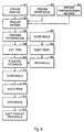
- Fig. 6 illustrates a method for producing the in-mould decorated product shown in fig. 5.
- a base foil which is to act as the support, bonding and protective structure of the patterned foil.
- the patterning step is shown generally as step 604.
- patterning may comprise any forms of patterning, including but not being limited to screen printing, offset printing, digital printing, etching, holographic picture generation, painting, sputtering, plating, perforating, glueing and placing stickers onto the base foil. Also more exotic operations such as attaching light guides, resistors or other electronic components to the foil structure qualify as patterning.
- the preforming step 605 where the patterned foil is preformed to conform to the inside of the outer injection moulded layer.
- This step belongs to the usual known form of in-mould decorating.
- the invention does not limit the selection of the preforming method.
- the preforming step it is possible to cut and trim the piece of foil coming into a single workpiece as is illustrated by step 606. It is not obligatory to cut and trim the foil at all at this stage, if the manufacturing apparatus allows the continuous foil to be led into the moulding step. Handling a continuous foil strip is sometimes more advantageous from the viewpoint of mass production than placing separately cut pieces of preformed foil into the moulds.
- a mould has been closed at step 607 and polymer resin has been injected into the mould at step 608.
- the grade of resin and the set of moulding parameters to be used at step 608 have most advantageously been selected to fulfill demanding criteria of good transparency or translucency, pleasant feel and visual appearance.
- the mould is opened. What happens next depends on the mould technology which is used. It is possible to remove the newly injection moulded outer layer from the mould altogether and to place it into another, completely separate mould where the foil and the inner layer are to be added thereto.
- the patterned, preformed and possibly also cut and trimmed foil is placed into the mould and against the appropriate surface of the outer layer.
- the mould is closed, and at step 612 more polymer resin is injected into the mould in order to produce the inner layer and to fuse the outer layer, the foil and the inner layer into an integrated structure.
- the grade of resin and the set of moulding parameters to be used at step 612 can be either the same as or different from those that were used at step 608. Using different grade of resin and/or different moulding parameters enables the manufacturer to optimise the second injection moulding step to fulfil criteria of e.g. good structural stiffness rather than fine external features.
- the mould is opened, and at step 614 the completed product is ejected from the mould. Surface finishing treatments and various trimming and upgrading steps may follow thereafter like in known injection moulding processes.
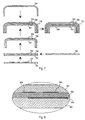
- FIG. 7 illustrates schematically the production of an injection moulded product for which there are first laminated two foils 701 and 702 together. At least one surface of at least one of the foils comprises patterns 703. After laminating the two foils together or in association therewith the foil structure is preformed. An outer layer 704 is produced by injection moulding, and the preformed foil structure is attached to the inner surface of the outer layer. Finally an inner layer 705 is injection moulded to the inside of the whole packet.
- Fig. 8 illustrates schematically the production of an injection moulded product for which there is provided a first foil 801 with patterns 802 on one side.
- the patterned first foil 801 is preformed, and an outer layer 803 is injection moulded.
- the preformed, patterned first foil 801 is placed the patterned side first against the inner surface of the outer layer 803, and an intermediate layer 804 is injection moulded onto the inside of the combined outer layer 803 and first foil 801.
- a second foil 805 is provided with patterns 806 on its one side.
- the patterned second foil 805 is preformed and placed the patterned side first against the inner surface of the combination consisting of the outer layer 803, the first foil 801 and the intermediate layer 804.
- Finally an inner layer 807 is injection moulded to the inside of the whole packet.
- In the end product there are three injection moulded layers, separated from each other by the patterned foils. If all patterns should be visible for external visual inspection, at least the outer and intermediate layers must be at least partly transparent or translucent.
- the outer layer(s) must be at least partly transparent or translucent.
- the secret security code pattern may be made of a thin metal layer sputtered or otherwise generated onto a surface of the foil.
- the secret security code there is at least one structural layer on each side of the secret security code that is opaque enough to hide the secret security code from visual inspection under normal conditions.
- Fig. 9 is an enlarged cross-sectional diagram of a part of an injection moulded product according to an embodiment of the invention.
- the product comprises an injection moulded outer layer 901, a foil 902 and an injection moulded inner layer 903, of which only the outer layer 901 is transparent or translucent to visible light.
- a secret security code pattern 905 which is hidden from normal visual inspection, because the opaque foil 902 hides it from outside and the opaque inner layer 903 hides it from the inside.
- the secret security code pattern 905 is only observable in a transillumination device which illuminates the product with other electromagnetic radiation than visible light, for which other electromagnetic radiation the outer layer 901, the decorative patterns 904, the foil 902 and the inner layer 903 are transparent or translucent but the secret security code pattern 905 is not. If the secret security code pattern 905 is made of metal and not of printing ink, it is no problem to place it against the inner layer since materials like metal are much more resistent to the erosion of molten polymer resin than printing inks.
- the injection moulded product is made as has been described above in association with figs. 5 and 6, with the exception that all used polymer resins are opaque to visible light.
- Fig. 10 illustrates schematically the production of an injection moulded product for which there is provided a single foil 1001, which comprises patterns 1002 on at least one surface thereof.
- the foil is preformed and placed into a mould, where a layer of (preferably) at least partly transparent or translucent material is injection moulded on top of the patterned foil 1001 to constitute an outer surface 1003 of the injection moulded product.
- Fig. 11 illustrates schematically a similar process where the difference to fig. 10 lies in the fact that the patterns 1102 are placed on the inside of the foil 1101 instead of that side that comes against the injection moulded top layer 1103.
- the advantage of the process of fig. 11 is the better resistance of the patterns 1102 against the conditions occurring during the injection moulding step.
- a method for manufacturing the injection moulded structures of figs. 10 and 11 is easily produced by slightly modifying the method of fig. 6.
- the modification includes leaving out steps 607, 608 and 609 and arranging the resin injecting step 612 so that resin is injected on top of the foil instead of below it as was previously explained.
Landscapes
- Engineering & Computer Science (AREA)
- Manufacturing & Machinery (AREA)
- Mechanical Engineering (AREA)
- Injection Moulding Of Plastics Or The Like (AREA)
Applications Claiming Priority (2)
| Application Number | Priority Date | Filing Date | Title |
|---|---|---|---|
| FI20002038A FI20002038A (fi) | 2000-09-15 | 2000-09-15 | Koristeltu ruiskupuristettu tuote ja menetelmä sen valmistamiseksi |
| FI20002038 | 2000-09-15 |
Publications (3)
| Publication Number | Publication Date |
|---|---|
| EP1188534A2 true EP1188534A2 (fr) | 2002-03-20 |
| EP1188534A3 EP1188534A3 (fr) | 2003-01-08 |
| EP1188534B1 EP1188534B1 (fr) | 2005-08-10 |
Family
ID=8559092
Family Applications (1)
| Application Number | Title | Priority Date | Filing Date |
|---|---|---|---|
| EP01660155A Expired - Lifetime EP1188534B1 (fr) | 2000-09-15 | 2001-08-30 | Procédé de fabrication d'un article décoré moulé par injection |
Country Status (5)
| Country | Link |
|---|---|
| US (2) | US6875301B2 (fr) |
| EP (1) | EP1188534B1 (fr) |
| CN (1) | CN1243632C (fr) |
| DE (1) | DE60112522T2 (fr) |
| FI (1) | FI20002038A (fr) |
Cited By (15)
| Publication number | Priority date | Publication date | Assignee | Title |
|---|---|---|---|---|
| WO2004043669A1 (fr) * | 2002-11-09 | 2004-05-27 | Braun Gmbh | Piece moulee par injection |
| EP1445117A1 (fr) * | 2003-01-29 | 2004-08-11 | Taiyi Precision Tech Corp. | Procédé pour la fabrication d'un article moulé par injection, decoré dans le moule |
| EP1447215A1 (fr) * | 2003-02-13 | 2004-08-18 | Veritas Ag | Matériau composite |
| EP1447233A1 (fr) | 2003-02-11 | 2004-08-18 | Taiyi Precision Tech Corp. | Méthode d'impression avec une combinaison d'impression offset et impression sérigraphique |
| EP1724088A1 (fr) * | 2005-05-20 | 2006-11-22 | BSH Bosch und Siemens Hausgeräte GmbH | Panneau de commande et/ou affichage |
| EP1754932A2 (fr) * | 2005-08-17 | 2007-02-21 | ULO Fahrzeugleuchten-GmbH | Elémént de construction à plusieurs parties, en particulier projecteur de véhicule, avec une surface pour masquer un joint de raccord entre deux parties |
| EP2179833A1 (fr) * | 2008-10-22 | 2010-04-28 | Samsung Electronics Co., Ltd. | Procédé de fabrication de produit moulé par injection avec un 3D structure sur la surface interne |
| EP2298528A1 (fr) * | 2009-09-16 | 2011-03-23 | Quin GmbH | Elément de décor et procédé de fabrication d'un élément de décor |
| CN102104640A (zh) * | 2009-12-18 | 2011-06-22 | 索尼爱立信移动通讯股份有限公司 | 用于移动通信设备的照明壳盖 |
| US8038919B2 (en) | 2006-07-06 | 2011-10-18 | Samsung Electro-Mechanics Co., Ltd. | Method of manufacturing film antenna using sputtering process |
| EP2461721A1 (fr) * | 2009-08-04 | 2012-06-13 | Ivoplast SRL | Tables et chaises |
| US8385706B2 (en) | 2005-01-31 | 2013-02-26 | Osram Opto Semiconductors Gmbh | Optical element and method for the production thereof |
| US8387232B2 (en) | 2007-07-11 | 2013-03-05 | Samsung Electro-Mechanics Co., Ltd. | Method of manufacturing antenna formed with case |
| RU2534051C1 (ru) * | 2011-02-01 | 2014-11-27 | Колгейт-Палмолив Компани | Устройство для ухода за полостью рта, имеющее декоративный элемент, и способ формирования такого устройства |
| EP2467658B1 (fr) * | 2009-08-21 | 2018-10-17 | BSH Hausgeräte GmbH | Compartiment à produit réfrigéré pour appareil de froid |
Families Citing this family (58)
| Publication number | Priority date | Publication date | Assignee | Title |
|---|---|---|---|---|
| US6768654B2 (en) * | 2000-09-18 | 2004-07-27 | Wavezero, Inc. | Multi-layered structures and methods for manufacturing the multi-layered structures |
| AT411044B (de) * | 2001-10-16 | 2003-09-25 | Burg Design Gmbh | Dekorelement |
| CN101172410B (zh) * | 2003-01-08 | 2011-12-28 | 雅马哈发动机株式会社 | 装饰用板、成形品、机动车辆及成形品的制造方法 |
| US20050106362A1 (en) * | 2003-11-13 | 2005-05-19 | Gene Kim | Energetic beam markable sheet |
| TWI248416B (en) * | 2004-03-12 | 2006-02-01 | Hon Hai Prec Ind Co Ltd | Transfer printing method for injection molding process |
| DE102004041833A1 (de) * | 2004-08-27 | 2006-03-02 | Leonhard Kurz Gmbh & Co. Kg | Dekorierter Spritzgussartikel, Verfahren zur Herstellung eines dekorierten Spritzgussartikels sowie Transferfolie zur Verwendung in einem derartigen Verfahren |
| CA2517940A1 (fr) * | 2004-09-24 | 2006-03-24 | Ems-Chemie Ag | Methode de moulage par injection de pieces en plastique |
| US20060076702A1 (en) * | 2004-10-07 | 2006-04-13 | Fu-Chi Tsai | Method of manufacturing a casing of an electronic product with surface decoration thereon |
| DE102004062477A1 (de) * | 2004-12-24 | 2006-07-06 | Bayer Materialscience Ag | Verfahren zur Herstellung eines Verbundformteiles aus Kunststoff und dessen Verwendung |
| EP1911566A4 (fr) * | 2005-07-25 | 2010-12-01 | Yamaha Motor Co Ltd | Procédé de production de moulures et véhicules automobiles |
| EP1829708B1 (fr) * | 2005-09-13 | 2009-04-15 | Yamaha Hatsudoki Kabushiki Kaisha | Feuille décorative, article moulé décoré et véhicule motorisé |
| CN101005738A (zh) * | 2006-01-21 | 2007-07-25 | 鸿富锦精密工业(深圳)有限公司 | 外壳及其制造方法 |
| CN101077672B (zh) * | 2006-05-26 | 2010-05-26 | 鸿富锦精密工业(深圳)有限公司 | 模内装饰用薄膜及其制造方法以及模内装饰制程 |
| US20080026721A1 (en) * | 2006-07-27 | 2008-01-31 | Swei Mu Wang | Method for making shell for electric product |
| US20080048360A1 (en) * | 2006-08-24 | 2008-02-28 | Arima Communications Corp. | Method for forming a front shell of a mobile communication device |
| EP1927455A1 (fr) * | 2006-11-28 | 2008-06-04 | Koninklijke Philips Electronics N.V. | Procédé pour fabriquer un élément de boîtier avec une surface décorative et une couche de prise, feuille décorative et élément de boîtier |
| WO2008154771A1 (fr) * | 2007-06-20 | 2008-12-24 | Dongguan Memtech Electronic Products Co., Ltd | Feuille de plastique pour moulage par injection présentant une texture 3d et son procédé de production |
| CN101412275B (zh) * | 2007-10-18 | 2010-09-01 | 上海举烛复合塑料有限公司 | 一种模内装饰射出成型的方法 |
| DE202007018007U1 (de) | 2007-12-22 | 2008-04-03 | Gerhardi Kunststofftechnik Gmbh | Mehrkomponenten IMD Einstiegsleiste |
| TWI365695B (en) * | 2008-04-02 | 2012-06-01 | Pegatron Corp | Case of an electronic device and method of fabricating the same |
| TWI331084B (en) * | 2008-05-12 | 2010-10-01 | Asustek Comp Inc | In-mold decoration device and manufacturing method thereof |
| CN101616556B (zh) * | 2008-06-27 | 2011-08-31 | 深圳富泰宏精密工业有限公司 | 电子装置的壳体及其制造方法 |
| CN101662898B (zh) * | 2008-08-28 | 2011-05-18 | 比亚迪股份有限公司 | 电子产品外壳及其制备方法和电子产品 |
| GB2463266B (en) * | 2008-09-05 | 2011-07-27 | Plastic Logic Ltd | Electronic document reader |
| US20110195224A1 (en) * | 2008-09-24 | 2011-08-11 | Bing Zhang | Shell, mobile communication terminal containing the same and preparation methods thereof |
| US20100086753A1 (en) * | 2008-10-02 | 2010-04-08 | Wade Johnson | Foiled articles and methods of making same |
| JP4335966B1 (ja) * | 2008-11-07 | 2009-09-30 | 戈普 吉野 | 模様付き椅子の製造方法及びその製造方法で製造された模様付き椅子 |
| EP2365928A1 (fr) * | 2008-11-14 | 2011-09-21 | L.C.S. Tech Ltd | Système et procédé de thermosoudage configurationnel de sacs plastiques |
| CN101844389B (zh) * | 2009-03-27 | 2013-02-06 | 金宇轩 | 模内涂装整合系统的加工方法 |
| KR101564783B1 (ko) | 2009-03-27 | 2015-11-02 | 삼성전자주식회사 | 사출물 제조 방법 |
| JP2011011523A (ja) * | 2009-07-06 | 2011-01-20 | Sony Corp | 多色成形方法、多色成形装置及び多色成形部品 |
| CN102034625A (zh) * | 2009-09-30 | 2011-04-27 | 鸿富锦精密工业(深圳)有限公司 | 按键制造方法及使用该方法制造的按键 |
| US8703036B1 (en) * | 2009-11-23 | 2014-04-22 | Funzone, Inc. | Silicone chew toy |
| WO2011071539A1 (fr) * | 2009-12-11 | 2011-06-16 | Flextronics Ap Llc | Système et procédé permettant de surmouler des pièces en plastique décorées |
| US20110258896A1 (en) * | 2010-04-23 | 2011-10-27 | Lomont Molding, Inc. | Detectable signage apparatus and method of making the same |
| SI2688723T1 (sl) * | 2011-03-21 | 2016-01-29 | Luxottica S.R.L. | Postopek in naprava za izdelavo okrašenih okvirjev očal |
| EP2763833B1 (fr) * | 2011-10-05 | 2020-03-25 | Saint-Gobain Glass France | Procédé de fabrication d'un élément de décoration en plastique |
| US9855731B2 (en) * | 2012-11-01 | 2018-01-02 | 3Form, Llc | Resin-based panel with encapsulated high-resolution image layer and methods of making same |
| CN104339531A (zh) * | 2013-08-08 | 2015-02-11 | 青岛佳友模具科技有限公司 | 一种内嵌件双色注塑的方法 |
| CN103481445A (zh) * | 2013-09-26 | 2014-01-01 | 张家港市锦丰润尔发五金塑料厂 | 塑料平板及其制作方法 |
| US10530018B2 (en) * | 2013-12-13 | 2020-01-07 | Infineon Technoogies Ag | Panel, a method for fabricating a panel and a method |
| US20160375676A1 (en) * | 2014-01-24 | 2016-12-29 | Verrana, Llc | Use of 3D printing for anticounterfeiting |
| CH709485B1 (de) * | 2014-04-11 | 2018-07-13 | Interglass Tech Ag | Verfahren zum Herstellen einer Linse durch Giessen. |
| TWI618625B (zh) * | 2014-10-03 | 2018-03-21 | 綠點高新科技股份有限公司 | 物件的製法及其製品 |
| DE102015209797B3 (de) * | 2015-05-28 | 2016-07-14 | Adidas Ag | Paneel für einen Ball |
| DE102015217744A1 (de) * | 2015-09-16 | 2017-03-16 | Nanogate PD Systems GmbH | Radom |
| DE102015221220A1 (de) * | 2015-10-29 | 2017-05-04 | Doma Gmbh | Verfahren zur Herstellung einer Kunststoffmatte mit einem strukturierten Abschnitt |
| US10821640B2 (en) | 2015-12-15 | 2020-11-03 | Merck Patent Gmbh | Process for the production of virtual three-dimensional patterns in mouldings |
| JP6332385B2 (ja) * | 2016-09-29 | 2018-05-30 | マツダ株式会社 | フィルム材のインサート成形方法及びその装置 |
| FR3066139B1 (fr) * | 2017-05-15 | 2020-12-04 | Automotive Lighting Rear Lamps France | Procede de fabrication d'une coque comprenant un film decoratif |
| KR102443605B1 (ko) * | 2017-09-06 | 2022-09-15 | 삼성디스플레이 주식회사 | 표시 장치용 커버 윈도우 및 그 제조 방법 |
| DE102017121558B3 (de) * | 2017-09-18 | 2019-03-07 | Hib Trim Part Solutions Gmbh | Verfahren zur Herstellung eines Zierteils für Fahrzeuge unter Nutzung einer verlorenen Dichtung und Zierteil |
| US11090876B2 (en) | 2018-09-18 | 2021-08-17 | Flex Ltd. | Assembly of sub-components by compression molding |
| DE102019106561A1 (de) * | 2019-03-14 | 2020-09-17 | Leonhard Kurz Stiftung & Co. Kg | Verfahren zur Herstellung eines Bauteils und Vorrichtung zur Herstellung eines Bauteils |
| DE102019124625A1 (de) * | 2019-09-12 | 2021-03-18 | Heyco IML Kunststofftechnik GmbH&Co.KG | Verfahren zur Herstellung eines Radoms für ein Kraftfahrzeug und entsprechendes Radom |
| US11175700B1 (en) * | 2020-05-14 | 2021-11-16 | Apple Inc. | Electronic devices with adjustable-appearance housing structures |
| DE102021132531A1 (de) | 2021-12-09 | 2023-06-15 | Endress+Hauser SE+Co. KG | Verfahren zum Herstellen zumindest eines Teilbereichs eines Gehäuses für ein Feldgerät |
| DE102021132536A1 (de) | 2021-12-09 | 2023-06-15 | Endress+Hauser SE+Co. KG | Verfahren zum Herstellen eines Feldgerätegehäuses |
Citations (7)
| Publication number | Priority date | Publication date | Assignee | Title |
|---|---|---|---|---|
| US3363039A (en) * | 1963-08-09 | 1968-01-09 | Asahi Dow Ltd | Injection molding processes for thermoplastic materials |
| EP0031525A2 (fr) * | 1979-12-14 | 1981-07-08 | Gesellschaft Für Zeit- Und Informationserfassung Mbh | Carte d'identification |
| US4330578A (en) * | 1979-10-10 | 1982-05-18 | Mitsubishi Rayon Co., Ltd. | Synthetic resin decorative article and process for producing same |
| WO1982003713A1 (fr) * | 1981-04-23 | 1982-10-28 | Haslop John Martin | Documents de securite |
| EP0633585A1 (fr) * | 1993-07-08 | 1995-01-11 | Philips Patentverwaltung GmbH | Boîtier pour appareils de télécommunication électrique |
| DE29701125U1 (de) * | 1997-01-23 | 1997-03-20 | Christophery GmbH, 58644 Iserlohn | Plakette |
| DE19610687A1 (de) * | 1996-03-19 | 1997-09-25 | Reum Ag | Verfahren zur Herstellung von Bedienblenden |
Family Cites Families (36)
| Publication number | Priority date | Publication date | Assignee | Title |
|---|---|---|---|---|
| US3298558A (en) * | 1963-01-30 | 1967-01-17 | Avon Prod Inc | Molded laminated article |
| US3312197A (en) * | 1965-10-15 | 1967-04-04 | Forrest W Smith | Facsimile coin embedded in plastic, and method of making same |
| US3839129A (en) * | 1970-09-25 | 1974-10-01 | Pictorial Prod Inc | Reflective foil and process |
| US3654062A (en) * | 1970-09-28 | 1972-04-04 | Standard Products Co | Injection molded decorative plaques |
| US3660211A (en) * | 1971-01-15 | 1972-05-02 | Norman Industries | Plastic article and method of production |
| GB1380255A (en) * | 1971-02-15 | 1975-01-08 | Creators Ltd | Decorative trim strips |
| JPS5919022B2 (ja) * | 1978-06-06 | 1984-05-02 | クルツジヤパン株式会社 | 立体装飾用金属熱転写材 |
| US4481160A (en) * | 1979-12-17 | 1984-11-06 | The D. L. Auld Company | Manufacture of decorative emblems |
| US4359633A (en) * | 1980-10-28 | 1982-11-16 | Bianco James S | Spectrally-limited bar-code label and identification card |
| DK146709C (da) * | 1980-12-09 | 1984-05-21 | Eskesen Brdr As | Fremgangsmaade til fremstilling af sproejtestoebte plastemner med indstoebte folier med dekorative og/eller beskrivende tryk samt apparat til brug ved udoevelse af fremgangsmaaden |
| US4538059A (en) * | 1981-09-16 | 1985-08-27 | Itr International Time Limited | Identification card with concealed coding and a simple reader module to decode it |
| JPS58203840A (ja) * | 1982-05-13 | 1983-11-28 | 吉田工業株式会社 | 合成樹脂製容器及びその製造方法 |
| DE3527412A1 (de) * | 1985-07-31 | 1987-02-12 | Kurz Leonhard Fa | Mehrlagige folie, insbesondere heisspraegefolie und verfahren zu deren herstellung |
| DE8616114U1 (de) * | 1986-06-14 | 1986-08-21 | Leonhard Kurz GmbH & Co, 8510 Fürth | Prägefolie, insbesondere Heißprägefolie |
| JPS6426420A (en) * | 1987-07-23 | 1989-01-27 | Nissha Printing | Device for injection molding and simultaneous decorating and manufacture of injection-molded and simultaneously decorated product |
| JPH01299016A (ja) * | 1988-05-26 | 1989-12-01 | Sakaiya Meihan Kk | 合成樹脂成形品及びその製造方法 |
| US4871714A (en) * | 1988-08-31 | 1989-10-03 | Eastman Kodak Company | Thermally-transferable fluorescent diphenyl ethylenes |
| DE3926578C1 (fr) * | 1989-08-11 | 1990-07-26 | Leonhard Kurz Gmbh & Co, 8510 Fuerth, De | |
| US5474817A (en) * | 1991-02-15 | 1995-12-12 | Tokai Kogyo Kabushiki Kaisha | Molding and production method thereof |
| JP2695348B2 (ja) * | 1992-04-28 | 1997-12-24 | 大日本印刷株式会社 | 射出成形同時絵付装置 |
| US5800759A (en) * | 1992-12-27 | 1998-09-01 | Nissha Printing Co., Ltd. | Insert molded article, and apparatus and method for producing the insert molded article |
| DE4313521C1 (de) * | 1993-04-24 | 1994-06-16 | Kurz Leonhard Fa | Dekorationsschichtaufbau und dessen Verwendung |
| US5795527A (en) * | 1994-04-29 | 1998-08-18 | Nissha Printing Co., Ltd. | Method of manufacturing decorated article using a transfer material |
| US5525179A (en) * | 1994-07-18 | 1996-06-11 | Empe-Werke Ernst Pelz Gmbh & Co. Kg | Method of manufacturing a lining part |
| US6264869B1 (en) * | 1996-11-28 | 2001-07-24 | 3M Innovative Properties Company | Method of preparing 3-dimensional, aesthetically appealing decorative emblems |
| JP3098455B2 (ja) * | 1997-05-14 | 2000-10-16 | 邦彦 小池 | 携帯電話機 |
| US6117384A (en) * | 1997-11-06 | 2000-09-12 | General Electric Co. | In-mold decorating process |
| US6164548A (en) * | 1998-02-05 | 2000-12-26 | Safecard Id System, Inc. | Methods of creating a tamper resistant informational article |
| US6468458B1 (en) * | 1998-10-23 | 2002-10-22 | Textron Automotive Company Inc, | Method for forming a composite product |
| FI982344A (fi) * | 1998-10-28 | 2000-04-29 | Nokia Mobile Phones Ltd | Tilaa säästävä matkaviestilaite |
| US6643001B1 (en) * | 1998-11-20 | 2003-11-04 | Revco, Inc. | Patterned platelets |
| IL129011A0 (en) * | 1999-03-16 | 2000-02-17 | Omd Devices L L C | Multi-layered optical information carriers with fluorescent reading and methods of their production |
| NL1015686C2 (nl) * | 2000-07-12 | 2002-01-15 | Dsm Nv | Werkwijze voor het met laserbestraling irreversibel aanbrengen van een voor het naakte oog onzichtbare markering op een polymeer vormdeel. |
| US6482346B1 (en) * | 2000-11-21 | 2002-11-19 | Ross Alcazar | Method for manufacturing an in-mold display |
| US6465102B1 (en) * | 2001-03-22 | 2002-10-15 | General Electric Company | Formed decorative article |
| US6790396B2 (en) * | 2001-08-29 | 2004-09-14 | Nokia Corporation | Method of making illuminated covers |
-
2000
- 2000-09-15 FI FI20002038A patent/FI20002038A/fi not_active Application Discontinuation
-
2001
- 2001-08-30 DE DE60112522T patent/DE60112522T2/de not_active Expired - Lifetime
- 2001-08-30 EP EP01660155A patent/EP1188534B1/fr not_active Expired - Lifetime
- 2001-09-13 US US09/952,228 patent/US6875301B2/en not_active Expired - Lifetime
- 2001-09-15 CN CN01143171.7A patent/CN1243632C/zh not_active Expired - Lifetime
-
2004
- 2004-12-09 US US11/007,864 patent/US20050098924A1/en not_active Abandoned
Patent Citations (7)
| Publication number | Priority date | Publication date | Assignee | Title |
|---|---|---|---|---|
| US3363039A (en) * | 1963-08-09 | 1968-01-09 | Asahi Dow Ltd | Injection molding processes for thermoplastic materials |
| US4330578A (en) * | 1979-10-10 | 1982-05-18 | Mitsubishi Rayon Co., Ltd. | Synthetic resin decorative article and process for producing same |
| EP0031525A2 (fr) * | 1979-12-14 | 1981-07-08 | Gesellschaft Für Zeit- Und Informationserfassung Mbh | Carte d'identification |
| WO1982003713A1 (fr) * | 1981-04-23 | 1982-10-28 | Haslop John Martin | Documents de securite |
| EP0633585A1 (fr) * | 1993-07-08 | 1995-01-11 | Philips Patentverwaltung GmbH | Boîtier pour appareils de télécommunication électrique |
| DE19610687A1 (de) * | 1996-03-19 | 1997-09-25 | Reum Ag | Verfahren zur Herstellung von Bedienblenden |
| DE29701125U1 (de) * | 1997-01-23 | 1997-03-20 | Christophery GmbH, 58644 Iserlohn | Plakette |
Cited By (22)
| Publication number | Priority date | Publication date | Assignee | Title |
|---|---|---|---|---|
| CN100431821C (zh) * | 2002-11-09 | 2008-11-12 | 布劳恩股份有限公司 | 牙刷主体 |
| WO2004043669A1 (fr) * | 2002-11-09 | 2004-05-27 | Braun Gmbh | Piece moulee par injection |
| US20150164209A1 (en) * | 2002-11-09 | 2015-06-18 | Braun Gmbh | Injection molded part |
| US9066577B1 (en) | 2002-11-09 | 2015-06-30 | Braun Gmbh | Injection molded part |
| EP1445117A1 (fr) * | 2003-01-29 | 2004-08-11 | Taiyi Precision Tech Corp. | Procédé pour la fabrication d'un article moulé par injection, decoré dans le moule |
| EP1447233A1 (fr) | 2003-02-11 | 2004-08-18 | Taiyi Precision Tech Corp. | Méthode d'impression avec une combinaison d'impression offset et impression sérigraphique |
| EP1447215A1 (fr) * | 2003-02-13 | 2004-08-18 | Veritas Ag | Matériau composite |
| US8385706B2 (en) | 2005-01-31 | 2013-02-26 | Osram Opto Semiconductors Gmbh | Optical element and method for the production thereof |
| US8509583B2 (en) | 2005-01-31 | 2013-08-13 | Osram Opto Semiconductors Gmbh | Optical element and method for the production thereof |
| EP1724088A1 (fr) * | 2005-05-20 | 2006-11-22 | BSH Bosch und Siemens Hausgeräte GmbH | Panneau de commande et/ou affichage |
| EP1754932A3 (fr) * | 2005-08-17 | 2008-10-29 | ULO Fahrzeugleuchten-GmbH | Elémént de construction à plusieurs parties, en particulier projecteur de véhicule, avec une surface pour masquer un joint de raccord entre deux parties |
| EP1754932A2 (fr) * | 2005-08-17 | 2007-02-21 | ULO Fahrzeugleuchten-GmbH | Elémént de construction à plusieurs parties, en particulier projecteur de véhicule, avec une surface pour masquer un joint de raccord entre deux parties |
| US8038919B2 (en) | 2006-07-06 | 2011-10-18 | Samsung Electro-Mechanics Co., Ltd. | Method of manufacturing film antenna using sputtering process |
| US8387232B2 (en) | 2007-07-11 | 2013-03-05 | Samsung Electro-Mechanics Co., Ltd. | Method of manufacturing antenna formed with case |
| EP2179833A1 (fr) * | 2008-10-22 | 2010-04-28 | Samsung Electronics Co., Ltd. | Procédé de fabrication de produit moulé par injection avec un 3D structure sur la surface interne |
| EP2461721A1 (fr) * | 2009-08-04 | 2012-06-13 | Ivoplast SRL | Tables et chaises |
| EP2467658B1 (fr) * | 2009-08-21 | 2018-10-17 | BSH Hausgeräte GmbH | Compartiment à produit réfrigéré pour appareil de froid |
| EP2298528A1 (fr) * | 2009-09-16 | 2011-03-23 | Quin GmbH | Elément de décor et procédé de fabrication d'un élément de décor |
| WO2011073854A1 (fr) * | 2009-12-18 | 2011-06-23 | Sony Ericsson Mobile Communications Ab | Couvercle de boîtier moulé éclairé pour un dispositif de communication mobile |
| CN102104640A (zh) * | 2009-12-18 | 2011-06-22 | 索尼爱立信移动通讯股份有限公司 | 用于移动通信设备的照明壳盖 |
| RU2534051C1 (ru) * | 2011-02-01 | 2014-11-27 | Колгейт-Палмолив Компани | Устройство для ухода за полостью рта, имеющее декоративный элемент, и способ формирования такого устройства |
| US9167890B2 (en) | 2011-02-01 | 2015-10-27 | Colgate-Palmolive Company | Oral care implement having a decorative member and a method of forming the same |
Also Published As
| Publication number | Publication date |
|---|---|
| US6875301B2 (en) | 2005-04-05 |
| FI20002038A0 (fi) | 2000-09-15 |
| CN1356205A (zh) | 2002-07-03 |
| FI20002038A (fi) | 2002-03-16 |
| US20050098924A1 (en) | 2005-05-12 |
| US20020048667A1 (en) | 2002-04-25 |
| DE60112522D1 (de) | 2005-09-15 |
| EP1188534B1 (fr) | 2005-08-10 |
| DE60112522T2 (de) | 2006-06-08 |
| EP1188534A3 (fr) | 2003-01-08 |
| CN1243632C (zh) | 2006-03-01 |
Similar Documents
| Publication | Publication Date | Title |
|---|---|---|
| US6875301B2 (en) | Method for manufacturing an injection moulded product | |
| EP2509770B1 (fr) | Système et procédé permettant de surmouler des pièces en plastique décorées | |
| EP1914067B1 (fr) | Procédé de fabrication d'un boîtier formé à partir de résine thermoplastique et d'un film polarisant | |
| JP6614151B2 (ja) | プラスチック成形品およびその製造方法 | |
| KR100894445B1 (ko) | 장식 성형품과 그 제조방법 | |
| US20110250400A1 (en) | Method of fabricating injection-molded product | |
| JP2022502284A (ja) | 装飾フィルム、転写フィルム、転写フィルムの使用、転写フィルムの製造方法、プラスチック成形品の装飾方法、およびプラスチック成形品 | |
| CN110267790A (zh) | 生产具有经装饰表面的塑料成型件的方法和具有经装饰表面的塑料成型件 | |
| KR102185508B1 (ko) | 전자제품용 외장커버 | |
| US7003267B2 (en) | Internal part design, molding and surface finish for cosmetic appearance | |
| KR101164056B1 (ko) | 유브이 전사를 이용한 필름상의 패턴 형성 방법 | |
| EP1467540B1 (fr) | Coque d'objet et procédé de réalisation | |
| JPH06134804A (ja) | インサートシート | |
| JP4246309B2 (ja) | 照光性絵付シートと照光性絵付成形品の製造方法 | |
| JP2001277293A (ja) | 加飾サンドイッチ成形品とその製造方法 | |
| JPH06106572A (ja) | 二色成形品とその製造方法 | |
| KR200284883Y1 (ko) | 금속질감을 표현한 합성수지패널 | |
| US9475274B2 (en) | Method for producing decorative elements, particularly insignia | |
| CN216466325U (zh) | 透光加饰成型品 | |
| JP2001062957A (ja) | 絵付インサートフィルムと絵付インサート成形品の製造方法 | |
| CN218505201U (zh) | 透光加饰成型品 | |
| JP2008265085A (ja) | 加飾樹脂成形品の製造方法 | |
| JP2003245939A (ja) | キーシート部材の製造方法 | |
| JP2006095690A (ja) | 裏面側から照光可能な成形同時加飾成形品 | |
| JP2003217396A (ja) | 多接点キーシート部材及びその製造方法 |
Legal Events
| Date | Code | Title | Description |
|---|---|---|---|
| PUAI | Public reference made under article 153(3) epc to a published international application that has entered the european phase |
Free format text: ORIGINAL CODE: 0009012 |
|
| AK | Designated contracting states |
Kind code of ref document: A2 Designated state(s): AT BE CH CY DE DK ES FI FR GB GR IE IT LI LU MC NL PT SE TR |
|
| AX | Request for extension of the european patent |
Free format text: AL;LT;LV;MK;RO;SI |
|
| PUAL | Search report despatched |
Free format text: ORIGINAL CODE: 0009013 |
|
| AK | Designated contracting states |
Kind code of ref document: A3 Designated state(s): AT BE CH CY DE DK ES FI FR GB GR IE IT LI LU MC NL PT SE TR |
|
| AX | Request for extension of the european patent |
Free format text: AL;LT;LV;MK;RO;SI |
|
| 17P | Request for examination filed |
Effective date: 20030322 |
|
| AKX | Designation fees paid |
Designated state(s): DE FR GB NL |
|
| 17Q | First examination report despatched |
Effective date: 20040421 |
|
| GRAP | Despatch of communication of intention to grant a patent |
Free format text: ORIGINAL CODE: EPIDOSNIGR1 |
|
| RTI1 | Title (correction) |
Free format text: METHOD FOR PRODUCING A DECORATED INJECTION MOULDED PRODUCT |
|
| RIN1 | Information on inventor provided before grant (corrected) |
Inventor name: VAEAENAENEN, KALLE Inventor name: MAEENPAEAE, TARMO Inventor name: SULASAARI, MIKA Inventor name: KAUPPI, MATTI |
|
| GRAS | Grant fee paid |
Free format text: ORIGINAL CODE: EPIDOSNIGR3 |
|
| GRAA | (expected) grant |
Free format text: ORIGINAL CODE: 0009210 |
|
| AK | Designated contracting states |
Kind code of ref document: B1 Designated state(s): DE FR GB NL |
|
| REG | Reference to a national code |
Ref country code: GB Ref legal event code: FG4D |
|
| REF | Corresponds to: |
Ref document number: 60112522 Country of ref document: DE Date of ref document: 20050915 Kind code of ref document: P |
|
| ET | Fr: translation filed | ||
| PLBE | No opposition filed within time limit |
Free format text: ORIGINAL CODE: 0009261 |
|
| STAA | Information on the status of an ep patent application or granted ep patent |
Free format text: STATUS: NO OPPOSITION FILED WITHIN TIME LIMIT |
|
| 26N | No opposition filed |
Effective date: 20060511 |
|
| PGFP | Annual fee paid to national office [announced via postgrant information from national office to epo] |
Ref country code: FR Payment date: 20100824 Year of fee payment: 10 |
|
| PGFP | Annual fee paid to national office [announced via postgrant information from national office to epo] |
Ref country code: GB Payment date: 20100825 Year of fee payment: 10 |
|
| GBPC | Gb: european patent ceased through non-payment of renewal fee |
Effective date: 20110830 |
|
| REG | Reference to a national code |
Ref country code: FR Ref legal event code: ST Effective date: 20120430 |
|
| PG25 | Lapsed in a contracting state [announced via postgrant information from national office to epo] |
Ref country code: GB Free format text: LAPSE BECAUSE OF NON-PAYMENT OF DUE FEES Effective date: 20110830 Ref country code: FR Free format text: LAPSE BECAUSE OF NON-PAYMENT OF DUE FEES Effective date: 20110831 |
|
| REG | Reference to a national code |
Ref country code: DE Ref legal event code: R082 Ref document number: 60112522 Country of ref document: DE Representative=s name: BECKER, KURIG, STRAUS, DE Ref country code: DE Ref legal event code: R081 Ref document number: 60112522 Country of ref document: DE Owner name: NOKIA TECHNOLOGIES OY, FI Free format text: FORMER OWNER: NOKIA CORP., 02610 ESPOO, FI |
|
| REG | Reference to a national code |
Ref country code: NL Ref legal event code: PD Owner name: NOKIA TECHNOLOGIES OY; FI Free format text: DETAILS ASSIGNMENT: VERANDERING VAN EIGENAAR(S), OVERDRACHT; FORMER OWNER NAME: NOKIA CORPORATION Effective date: 20151111 |
|
| PGFP | Annual fee paid to national office [announced via postgrant information from national office to epo] |
Ref country code: NL Payment date: 20170814 Year of fee payment: 17 |
|
| REG | Reference to a national code |
Ref country code: DE Ref legal event code: R082 Ref document number: 60112522 Country of ref document: DE Representative=s name: BECKER, KURIG, STRAUS, DE Ref country code: DE Ref legal event code: R081 Ref document number: 60112522 Country of ref document: DE Owner name: PROVENANCE ASSET GROUP LLC, PITTSFORD, US Free format text: FORMER OWNER: NOKIA TECHNOLOGIES OY, ESPOO, FI Ref country code: DE Ref legal event code: R082 Ref document number: 60112522 Country of ref document: DE Representative=s name: BECKER-KURIG-STRAUS PATENTANWAELTE PARTNERSCHA, DE Ref country code: DE Ref legal event code: R082 Ref document number: 60112522 Country of ref document: DE Representative=s name: BECKER & KURIG PARTNERSCHAFT PATENTANWAELTE MB, DE Ref country code: DE Ref legal event code: R082 Ref document number: 60112522 Country of ref document: DE Representative=s name: BECKER & KURIG PARTNERSCHAFT PATENTANWAELTE PA, DE |
|
| REG | Reference to a national code |
Ref country code: NL Ref legal event code: MM Effective date: 20180901 |
|
| PG25 | Lapsed in a contracting state [announced via postgrant information from national office to epo] |
Ref country code: NL Free format text: LAPSE BECAUSE OF NON-PAYMENT OF DUE FEES Effective date: 20180901 |
|
| PGFP | Annual fee paid to national office [announced via postgrant information from national office to epo] |
Ref country code: DE Payment date: 20200901 Year of fee payment: 20 |
|
| REG | Reference to a national code |
Ref country code: DE Ref legal event code: R071 Ref document number: 60112522 Country of ref document: DE |