EP1187737B1 - Manueller hebelantrieb für stellvorrichtungen an sitzen, insbesondere an kraftfahrzeugsitzen - Google Patents
Manueller hebelantrieb für stellvorrichtungen an sitzen, insbesondere an kraftfahrzeugsitzen Download PDFInfo
- Publication number
- EP1187737B1 EP1187737B1 EP01938035A EP01938035A EP1187737B1 EP 1187737 B1 EP1187737 B1 EP 1187737B1 EP 01938035 A EP01938035 A EP 01938035A EP 01938035 A EP01938035 A EP 01938035A EP 1187737 B1 EP1187737 B1 EP 1187737B1
- Authority
- EP
- European Patent Office
- Prior art keywords
- lever
- spring
- rotation
- axis
- drive according
- Prior art date
- Legal status (The legal status is an assumption and is not a legal conclusion. Google has not performed a legal analysis and makes no representation as to the accuracy of the status listed.)
- Expired - Lifetime
Links
Images


Classifications
-
- B—PERFORMING OPERATIONS; TRANSPORTING
- B60—VEHICLES IN GENERAL
- B60N—SEATS SPECIALLY ADAPTED FOR VEHICLES; VEHICLE PASSENGER ACCOMMODATION NOT OTHERWISE PROVIDED FOR
- B60N2/00—Seats specially adapted for vehicles; Arrangement or mounting of seats in vehicles
- B60N2/02—Seats specially adapted for vehicles; Arrangement or mounting of seats in vehicles the seat or part thereof being movable, e.g. adjustable
- B60N2/22—Seats specially adapted for vehicles; Arrangement or mounting of seats in vehicles the seat or part thereof being movable, e.g. adjustable the back-rest being adjustable
-
- B—PERFORMING OPERATIONS; TRANSPORTING
- B60—VEHICLES IN GENERAL
- B60N—SEATS SPECIALLY ADAPTED FOR VEHICLES; VEHICLE PASSENGER ACCOMMODATION NOT OTHERWISE PROVIDED FOR
- B60N2/00—Seats specially adapted for vehicles; Arrangement or mounting of seats in vehicles
- B60N2/90—Details or parts not otherwise provided for
- B60N2/919—Positioning and locking mechanisms
- B60N2/933—Positioning and locking mechanisms rotatable
- B60N2/938—Positioning and locking mechanisms rotatable and provided with braking systems
-
- B—PERFORMING OPERATIONS; TRANSPORTING
- B60—VEHICLES IN GENERAL
- B60N—SEATS SPECIALLY ADAPTED FOR VEHICLES; VEHICLE PASSENGER ACCOMMODATION NOT OTHERWISE PROVIDED FOR
- B60N2/00—Seats specially adapted for vehicles; Arrangement or mounting of seats in vehicles
- B60N2/90—Details or parts not otherwise provided for
- B60N2/919—Positioning and locking mechanisms
- B60N2/933—Positioning and locking mechanisms rotatable
- B60N2/943—Stepwise movement mechanisms, e.g. ratchets
-
- Y—GENERAL TAGGING OF NEW TECHNOLOGICAL DEVELOPMENTS; GENERAL TAGGING OF CROSS-SECTIONAL TECHNOLOGIES SPANNING OVER SEVERAL SECTIONS OF THE IPC; TECHNICAL SUBJECTS COVERED BY FORMER USPC CROSS-REFERENCE ART COLLECTIONS [XRACs] AND DIGESTS
- Y10—TECHNICAL SUBJECTS COVERED BY FORMER USPC
- Y10T—TECHNICAL SUBJECTS COVERED BY FORMER US CLASSIFICATION
- Y10T74/00—Machine element or mechanism
- Y10T74/20—Control lever and linkage systems
- Y10T74/20576—Elements
- Y10T74/20636—Detents
-
- Y—GENERAL TAGGING OF NEW TECHNOLOGICAL DEVELOPMENTS; GENERAL TAGGING OF CROSS-SECTIONAL TECHNOLOGIES SPANNING OVER SEVERAL SECTIONS OF THE IPC; TECHNICAL SUBJECTS COVERED BY FORMER USPC CROSS-REFERENCE ART COLLECTIONS [XRACs] AND DIGESTS
- Y10—TECHNICAL SUBJECTS COVERED BY FORMER USPC
- Y10T—TECHNICAL SUBJECTS COVERED BY FORMER US CLASSIFICATION
- Y10T74/00—Machine element or mechanism
- Y10T74/20—Control lever and linkage systems
- Y10T74/20576—Elements
- Y10T74/20636—Detents
- Y10T74/20648—Interrelated lever release
Definitions
- the invention relates to a manual lever drive for actuators Sitting, in particular on motor vehicle seats, for implementing a lifting movement in a discontinuous rotation including one Stepper transmission (see for example US-A-5 664 836, the generic term corresponding).
- Stepping gearbox for converting a reciprocal lifting movement into a discontinuous rotational movements are in the field of motor vehicle seats already in use in various versions, often with ratchet and Pinch roller freewheels are used.
- For ergonomic operation to achieve are often after the implementation of the lifting movement in a Rotational motion rotary gearbox used to To bring forces and parameters into relation to each other.
- a Many of the mechanisms used require internal functions to function correctly Control paths for their activation, such as with ratchet ratchets first a jack must be engaged before the movement ultimately can be transferred.
- a jack must be engaged before the movement ultimately can be transferred.
- the object of the invention is a manual lever drive for actuators to create, which eliminates the aforementioned disadvantages of known systems, and at which in particular the output angle of rotation compared to that in the hand lever initiated stroke angle is increased and the translation to be achieved controllable is, i.e. the translation does not cover an entire stroke, but within the Hubes degree by degree can be effected.
- Two axes of rotation are essential in the present solution, with the first one Axis of rotation of the hand lever is mounted, while the second axis of rotation Represents drive member for the stepping mechanism, with this the second Axis of rotation forming drive member, the transmission member is rotatably connected, which in turn can be operated by the hand lever. Due to the distance of the two axes of rotation to each other and by the distance of the second axis of rotation to The point of contact of the hand lever with the transmission element results from deflection the hand lever by a certain angle a much higher angle on Transmission link and thus a larger angle of rotation at the second, the Stepping mechanism driving axis of rotation. This also reduces that for Operator noticeable empty angle of a system in the ratio of the aforementioned distances is reduced.
- a translation element is used in a first embodiment of the invention with the drive member rotatably connected pivot lever, which by means of the load arm of the hand lever over and under engaging driver by the hand lever in one or other direction of rotation is pivotable.
- the drivers of the Pivot lever advantageous as protruding from the pivot lever and Control recesses formed on the load arm of the hand lever contacting pin.
- the swivel lever has a return arm on, which is acted upon by a fixed spring member and from each Angular position can be reset to the zero position.
- a fixed spring member It may be a spring member Casing of the stepping mechanism fixed spiral spring can be used with radially protruding spring fingers over the return arm of the pivot lever engages below.
- the loaded spring leg experiences with a large counterweight on Swivel lever such a load, which causes the spring to bend around the Clamping point leads and in interaction with the correspondingly curved Control surfaces on the end section of the load arm of the hand lever a shift of Experiences contact points from the second axis of rotation backwards.
- This has one automatic change of the translation ratio.
- the translation changes depending on the load by using only the examples mentioned above Spring legs that form elastic elements within the transmission chain.
- Gear ratio is fixed with a on the lever bracket of the swivel lever Achieved spring shoe, which has a U-shaped support body, on whose the Load arm of the hand lever spaced legs each one multilevel spring clip is fixed between which the load arm of the hand lever with contact sections during its pivoting movement
- each spring clip can be spaced three in a row have arranged contact or clip sections, which gradually become narrower Load arm of the hand lever with clamping projections with increasing clamping force to capture. This creates three load levels, the individual Bracket sections are designed so that the to push the Clamp sections required force with increasing distance of the concerned Bracket section of the second axis of rotation is larger.
- the output torque is the force above that closest to the axis of rotation Transfer bracket section, so that with small loads a large translation is realized.
- the force that can be transmitted at this point is determined by the opening force of the Limited bracket section. Now the output load rises to a level above transmissible force on the first bracket section, the force over the second clamp section, slightly more distant from the axis of rotation. This means that the translation at this point is smaller than before.
- another, third contact point of the associated bracket section applies The above analog.
- Translation ratio could also create an institution where the Gear ratio is controlled consciously. This could be done, for example happen that a push button is arranged on the hand lever, which over a Sliding linkage with a both opposite the load arm of the hand lever as well is connected to the link bracket slidable cage through which upon actuation of the push button by the user a structurally determined Translation is activated, for example, a quick setting at high To achieve translation.
- a translation mechanism are Upstream switching mechanisms.
- a lever drive can be provided, in which the stepping mechanism in a special Embodiment is integrated.
- the wrap spring it is advantageous Embodiment of the subject matter of the translation member from a the second axis of rotation non-rotatably connected winding roller and one of these comprehensive wrap spring formed, the wrap spring to be elastic Driver arms shaped spring ends, between which a cam head on the load arm of the hand lever.
- the drive arms are the wrap spring advantageously acted upon by a spring element in the sense of zero reset.
- the elastic drive arms of the wrap spring are not only used for Activation of the clutch function, but are at the same time as themselves depending on the load, bending contact surfaces to the curve head on the load arm of the Hand lever trained and thus enable a high level of functional integration.
- Wrap spring closed for this direction of movement, and the drum initially taken high translation the gear ratio due to the sliding of the cam head on the respective driving arm automatically adapts to the load.
- the previously driven driver arm in front of the return spring element becomes a hand lever so loaded that the wrap spring opens, and therefore no longer the drum is driven, but due to friction in the downstream Seat adjustment element remains in this position. Since with accordingly opposite pivoting movement of the load arm on the hand lever the aforementioned Effect is also, but takes place in a different direction of movement is a double-acting step switch with integrated, automatically load-dependent Translation realized.
- Another embodiment of this, integrated with the lever drive Step switch mechanism can preferably be achieved by the transmission element of a drum pot connected to the second axis of rotation in a rotationally fixed manner and one arranged wrap spring is formed, the wrap spring for Radially protruding driver arms at their spring ends has overlapped by a claw arranged on the load arm of the hand lever are. Because depending on the design of the seat adjustment element, the internal friction may be less than the friction when returning the wrap spring, can use two, each in one direction Acting wrap springs can be advantageous, so that return springs may be omitted can be.
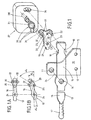
- the lever drive shown in FIG. 1 has a mounting hole 12 fixed support arm 10, the bearing bore 11 of one not Bearing pin shown is penetrated, which in turn the receiving hole 14 of a hand lever 13 pivotally mounted.
- the hand lever 13 is opposite his Pivot formed as a two-sided lever and has one with a handle part 17th provided power arm 15, which from the load arm 16 through the receiving bore 14 is separated.
- This load arm 16 is at a certain distance from Receiving hole 14 on its two opposite longitudinal sides Control recesses 18 on, the drivers 21 formed as a pin 22nd of a pivoting lever 20 functioning as a transmission member 19 making contact or are undermined.
- a driving hole 23 arranged to rotate with a drive member forming a second axis of rotation 25 26 is connected, the one provided with profiles for rotary driving and in a Step switch 27 may be a confluent wave.
- the drive member 26 in the Step switch 27 initiated rotary movement is from the step switch passed on via an output shaft 28 to an actuating device, not shown, which is, for example, a joint fitting for adjusting the inclination of the Backrest of a vehicle seat can act.
- Fig. 1A the initial position to be referred to as zero position is shown, in which both the hand lever 13 and the one acting as a translation member 19 Swivel lever 20 has no angular design. Only when the hand lever 13 around the angle ⁇ H shown in FIG. 1B - in the present case downwards - was pivoted, results from the rotational driving of the pin 22 as Transmission link 19 acting pivot lever 20 for the second axis of rotation 25 a swivel angle of ⁇ A. From the mere schematic representation of Fig. 1B it can be seen that the pivot angle ⁇ A of the pivot lever 20 by Is much larger than the swivel angle ⁇ H of about the first axis of rotation 24 in this angle pivoted hand lever 13. The size of the translation is depending on the ratio of the distances between the axes of rotation 24 and 25 on the one hand and between the axis of rotation 25 and the force application point on each applied pin 22.
- the first axis of rotation 24 is also by mounting the hand lever 13 with its receiving bore 14 in relation to given the bearing bore 11 of the support arm 10.
- the load arm 16 of the hand lever 13 has at its free end an end portion 35, both at its Has control surfaces 36 on the top and on its underside.
- This Control surfaces 36 are overlapped by a spring shoe 37, which with a Lever bracket 38 is connected and together with this a pivot lever 20th forms which represents the translation member 19.
- the Fastening holes for the spring shoe 37 has a lever tab 38 Driver bore 39, into which a previously mentioned drive member of the in Fig. 2nd Stepping mechanism not shown engages torque-transmitting, which Center of the driver bore 39 and the center of the drive member the second Form axis of rotation 25.
- the spring shoe 37 is U-shaped and faces projecting spring leg 40 on its web, which with the control surfaces 36 on Contact end section 35 of the load arm 16 from the hand lever 13.
- the contact point moves 41 of the control surface 36 on the spring leg 40 with respect to the second axis of rotation 25 radially away from this into the position shown in FIG. 2B. If necessary, while bending up the spring leg 40 resting on the upper control surface 36 the pivoting lever 20 belonging to the transmission member 19 about the second axis of rotation 25 pivoted counterclockwise into the angular position ⁇ A, the second axis of rotation 25 is also rotated by the angle ⁇ A. How 2B, the angle ⁇ A is a multiple larger than the angle ⁇ H. Since the further pivoting of the hand lever 13 the contact point 41 will also shift further in the radial direction an automatic, stepless during the pivoting movement of the hand lever 13 Change the gear ratio, which also changes the power ratio change in the aforementioned sense.
- FIG. 3 An embodiment modified from FIG. 2 is shown in FIG. 3.
- the spring shoe 37 'sets consists of a U-shaped support body 42 and multi-stage spring clips 43 together, of which one spring clip 43 on each leg 44 or 45 of the Support body 42 is fixed.
- each spring clip 43 has three spaced one behind the other Contact sections 46, which are designed like clips and with the load arm 16 of the hand lever 13 can come into contact when it is pivoted.
- the load arm 16 advantageously points to the contact sections 46 cooperating points on clamping projections 47, the corresponding Load between the respective contact sections 46 of the spring clip 43 can penetrate and thus the pivot lever 20 with its lever bracket 38 in pivot in a way that the second axis of rotation 25 a corresponding Experiences angular rotation and this to the also not shown Stepper transmission transmits.
- FIGS. 4 and 4A is the hand lever 13 in turn mounted on a first axis of rotation 24 on the fixed support arm 10.
- the Load arm 16 of this hand lever 13 has a cam head 48 at its free end on between the spring ends 50 formed into elastic carriers 21 a Wrap spring 49 summarizes.
- the wrap spring 49 is in turn on the jacket one Winding roller 51 arranged and takes this by static friction as a result of their Spring force in the event of a pivoting of a driver 21 in the corresponding Direction of rotation with.
- the winding roll 51 has a e.g. profiled Driving bore 23, which in turn is a drive member for the actuating device receives.
- the center of this driving bore is the second axis of rotation 25 to view the first axis of rotation which supports the hand lever 13 on the support arm 10 24 is arranged remotely.
- Each driver of the wrap spring 49 is for the purpose of Zero resetting is acted upon by a stationary spring element 52 (FIG. 4A).
- the Cam head 48 When initiating a lifting movement in the hand lever 13, the Cam head 48 the respective driver 21 of the wrap spring 49 is pivoted, whereby a rotational driving of the winding roller 51 in the corresponding The sense of pivoting takes place and finally also the second axis of rotation 25 forming drive member is rotated with.
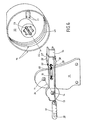
- FIG. 5 is again a modification of the 4 and 4A apparent embodiment.
- the hand lever 13 via a first axis of rotation 24 on the fixedly arranged support arm 10 stored.
- the second axis of rotation 25 is in the driving bore 23 arranged, but not shown in Fig. 5 formed drive member, the Driving bore 23 is part of a drum pot 53, in the interior thereof a wrap spring 49 is arranged.
- wrap springs 49 and Drum pot 53 the transmission member 19.
- This wrap spring 49 also assigns Carriers 21 shaped spring ends by a claw 54 at the end of the Load arm 16 of the hand lever 13 are overlapped. How this works Embodiment takes place in the same way as in that of FIGS. 4 and 4A apparent embodiment.
- FIG. 6 The embodiment shown in FIG. 6 in turn represents a modification of the embodiment shown in FIG. 5.
- the claw 54 as Guide rail prepared on the load arm 16 of the hand lever 13, on the one Link cage 57 is slidably disposed, the sliding path in the direction of the first axis of rotation 24 is limited by a stop 59 on the load arm 16.
- To the Link cage 57 is connected to a sliding linkage 56, which with a Handle part 17 arranged push button 55 is connected.
- the link cage 58 When depressing the Push button 55 is the link cage 58 with its contact points 58 for the Abutment on the drivers 21 forming beads with respect to the second axis of rotation 25 moved backwards so that the transmission ratio changes.
Landscapes
- Engineering & Computer Science (AREA)
- Aviation & Aerospace Engineering (AREA)
- Transportation (AREA)
- Mechanical Engineering (AREA)
- Seats For Vehicles (AREA)
- Chairs For Special Purposes, Such As Reclining Chairs (AREA)
- Chair Legs, Seat Parts, And Backrests (AREA)
- Mechanical Control Devices (AREA)
- Arrangement Or Mounting Of Control Devices For Change-Speed Gearing (AREA)
Description
- Fig. 1
- ein erstes Ausführungsbeispiel eines manuellen Hebelantriebes zur Einleitung eines unveränderlich übersetzten Stellhubes in ein Schrittschaltwerk, in einer schematischen, perspektivischen Darstellung,
- Fig. 1A
- den aus Fig. 1 ersichtlichen Hebelantrieb in einer schematischen, verkleinerten Seitenansicht, wobei sich der Hebelantrieb in Nullstellung befindet,
- Fig. 1B
- den in Fig. 1A dargestellten Hebelantrieb, ebenfalls in Seitenansicht in einer aus der Ruhelage ausgeschwenkten Stellung,
- Fig. 2
- ein weiteres Ausführungsbeispiel eines Hebelantriebes, dessen Übersetzungsverhältnis während der Hebelverschwenkung selbsttätig, stufenlos veränderbar ist, ebenfalls in einer schematischen, perspektivischen Darstellung,
- Fig. 2A
- den aus Fig. 2 ersichtlichen Hebelantrieb in einer schematischen, verkleinerten Seitenansicht, bei dem sich der Handhebel in Nullage befindet,
- Fig. 2B
- den aus Fig. 2A ersichtlichen Hebelantrieb in einer Seitenansicht, bei dem durch Ausschwenken des Handhebels auch der Schwenkhebel in entsprechender Weise ausgelenkt ist,
- Fig. 3
- eine Abwandlung des aus Fig. 2 ersichtlichen Hebelantriebes in einer schematischen, perspektivischen Darstellung, wobei der Schwenkhebel für ein mehrstufiges Übersetzungsverhältnis hergerichtet ist,
- Fig. 4
- ein weiteres Ausführungsbeispiel eines Hebelantriebes, ebenfalls in einer schematischen, perspektivischen Darstellung, bei dem in das Übersetzungsglied das Schrittschaltwerk durch Verwendung einer Schlingfeder integriert ist,
- Fig. 4A
- das aus Fig. 4 ersichtliche Schrittschaltwerk in einer schematischen, verkleinerten Seitenansicht, bei dem sich der mit einem Kurvenkopf versehene Lastarm des Handhebels in einer Nullstellung befindet,
- Fig. 5
- ein weiteres Ausführungsbeispiel eines Hebelantriebes in einer schematischen, perspektivischen Darstellung, wobei sich eine vom Lastarm des Handhebels betätigbare Schlingfeder im Inneren eines Trommeltopfes befindet,
- Fig. 6
- ein in Bezug auf Fig. 5 modifiziertes, analog dargestelltes Ausführungsbeispiel, bei dem das Übersetzungsverhältnis des Hebelantriebes auswählbar ist.
- 10
- Tragarm
- 11
- Lagerbohrung, in 10
- 12
- Befestigungsbohrung, in 10
- 13
- Handhebel
- 14
- Aufnahmebohrung, in 13
- 15
- Kraftarm, von 13
- 16
- Lastarm, von 13
- 17
- Griffteil, an 15
- 18
- Steuerausnehmung, an 16
- 19
- Übersetzungsglied
- 20
- Schwenkhebel
- 21
- Mitnehmer
- 22
- Zapfen
- 23
- Mitnahmebohrung
- 24
- Drehachse, erste
- 25
- Drehachse, zweite
- 26
- Antriebsglied
- 27
- Schrittschaltwerk
- 28
- Abtriebsglied
- 29
- Rückstellarm, an 20
- 30
- Federglied
- 31
- Spiralfeder
- 32
- Federfinger
- 33
- Mitnehmerbohrung
- 34
- Sperrzapfen
- 35
- Endabschnitt, von 16
- 36
- Steuerfläche
- 37
- Federschuh
- 37'
- Federschuh
- 38
- Hebellasche
- 39
- Mitnehmerbohrung
- 40
- Federschenkel
- 41
- Kontaktpunkt
- 42
- Tragkörper
- 43
- Federklammer
- 44
- Schenkel, von 42
- 45
- Schenkel, von 42
- 46
- Kontaktabschnitt, an 43
- 47
- Klemmvorsprung
- 48
- Kurvenkopf
- 49
- Schlingfeder
- 50
- Federende, von 49
- 51
- Wickelrolle
- 52
- Federglied
- 53
- Trommeltopf
- 54
- Klaue
- 55
- Druckknopf
- 56
- Schiebegestänge
- 57
- Kulissenkäfig
- 58
- Kontaktpunkt
- 59
- Anschlag
- 60
- Rückholfeder
Claims (12)
- Manueller Hebelantrieb für Stellvorrichtungen an Sitzen, insbesondere Kraftfahrzeugsitzen, zur Umsetzung einer Hubbewegung in eine diskontinuierliche Rotationsbewegung unter Einbeziehung eines Schrittschaltwerkes (27), dessen Abtriebsglied (28) mit einem rotatorisch bewegbaren Stellglied der Stellvorrichtung gekuppelt ist, während das Antriebsglied (26) des Schrittschaltwerkes (27) mit einem von einem Handhebel (13) betätigten Übersetzungsglied (19) drehmomentübertragend verbunden ist, wobei der Handhebel (13) an einem Tragarm (10) um eine erste Drehachse (24) schwenkbar gelagert ist,
das Übersetzungsglied (19) mit dem eine zweite Drehachse (25) bildenden Antriebsglied (26) drehfest verbunden ist
und wobei bei Auslenkung des Lastarms (16) des Handhebels (13) um einen Schwenkwinkel (αH) das auf einer zweiten Drehachse (25) angeordnete Übersetzungsglied (19) in eine den zugehörigen Drehwinkel (αA) der das Antriebsglied (26) des Schrittschaltwerkes (27) aufnehmenden zweiten Drehachse (25) gegenüber dem Schwenkwinkel (αH) vergrößernde Schwenkbewegung überführt wird,
dadurch gekennzeichnet, dass
der Lastarm (16) des Handhebels (13) im Abstand zur Drehachse (24) an seinen einander gegenüberliegenden Längsseiten Steuerflächen (18, 36, 48, 54) aufweist, die von Mitnehmern (21, 40) des Übersetzungsgliedes (19) kontaktierend über- bzw. untergriffen sind. - Hebelantrieb nach Anspruch 1, dadurch gekennzeichnet, dass das Übersetzungsglied (19) als mit dem Antriebsglied (26) drehfest verbundener Schwenkhebel (20) ausgebildet ist, der mittels den Lastarm (16) des Handhebels (13) über- und untergreifende Mitnehmer (21) durch den Handhebel (13) im einen oder anderen Drehsinne verschwenkbar ist.
- Hebelantrieb nach Anspruch 2, dadurch gekennzeichnet, dass die Mitnehmer (21) des Schwenkhebels (20) als vom Schwenkhebel abragende, und Steuerausnehmungen (18) am Lastarm (16) des Handhebels (13) kontaktierende Zapfen (22) ausgebildet sind.
- Hebelantrieb nach Anspruch 2 oder 3, dadurch gekennzeichnet, dass der Schwenkhebel (20) einen Rückstellarm (29) aufweist, der von einem ortsfest gehalterten Federglied (30) beaufschlagt und aus jeder Drehwinkellage in die Nullage rückstellbar ist.
- Hebelantrieb nach Anspruch 4, dadurch gekennzeichnet, dass als Federglied (30) eine am Gehäuse des Schrittschaltgetriebes (27) festgelegte Spiralfeder (31) verwendet ist, die mit radial abragenden Federfingern (32) den Rückstellarm (29) des Schwenkhebels (20) über- und untergreift.
- Hebelantrieb nach Anspruch 1 oder 2, dadurch gekennzeichnet, dass der als Übersetzungsglied (19) ausgebildete Schwenkhebel (20) aus einem mit einer Hebellasche (38) verbundenen Federschuh (37) gebildet ist, der zwischen zwei im Abstand zueinander angeordneten Federschenkeln (40) einen gekrümmte Steuerflächen (36) aufweisenden Endabschnitt (35) am Lastarm (16) des Handhebels (13) kontaktierend aufnimmt.
- Hebelantrieb nach Anspruch 6, dadurch gekennzeichnet, dass der an der Hebellasche (38) des Schwenkhebels (20) festgelegte Federschuh (37) einen U-förmigen Tragkörper (42) aufweist, an dessen den Lastarm (16) des Handhebels (13) abstandsweise übergreifenden Schenkeln (44, 45) je eine mehrstufige Federklammer (43) festgelegt ist, zwischen die der Lastarm (16) des Handhebels (13) mit Kontaktabschnitten (46) während seiner Schwenkbewegung fortlaufend faßt.
- Hebelantrieb nach Anspruch 7, dadurch gekennzeichnet, dass jede Federklammer (43) drei abstandsweise hintereinander angeordnete Kontaktabschnitte (46) aufweist, die fortlaufend enger werdend, den Klemmvorsprünge (47) aufweisenden Lastarm (16) des Handhebels (13) mit steigender Klemmkraft erfassen.
- Hebelantrieb nach Anspruch 1, dadurch gekennzeichnet, dass das Übersetzungsglied (19) aus einer mit der zweiten Drehachse (25) drehfest verbundenen Wickelrolle (51) und einer diese umfassenden Schlingfeder (49) gebildet ist, und die Schlingfeder (49) zu elastischen Mitnehmern (21) geformte Federenden (50) aufweist, zwischen die ein Kurvenkopf (48) am Lastarm (16) des Handhebels (13) faßt.
- Hebelantrieb nach Anspruch 9, dadurch gekennzeichnet, dass die Mitnehmer (21) der Schlingfeder (49) durch jeweils ein Federglied (52) im Sinne der Nullrückstellung beaufschlagt sind.
- Hebelantrieb nach Anspruch 1, dadurch gekennzeichnet, dass das Übersetzungsglied (19) aus einem mit der zweiten Drehachse (25) drehfest verbundenen Trommeltopf (53) und einer darin angeordneten Schlingfeder (49) gebildet ist und die Schlingfeder (49) zum Trommelmittelpunkt radial vorragende Mitnehmer (21) an ihren Federenden aufweist, die von einer am Lastarm (16) des Handhebels (13) angeordneten Klaue (54) übergriffen sind.
- Hebelantrieb nach Anspruch 11, dadurch gekennzeichnet, dass die Lage eines an einer verschiebbaren Kulisse (57) gebildeten Kontaktpunktes (58) zwischen dem Handhebel (13) und dem Übersetzungsglied (19) mittels weiterer Betätigungsvorrichtung (55, 56, 57) bewußt von der Bedienungsperson wählbar ist.
Applications Claiming Priority (3)
| Application Number | Priority Date | Filing Date | Title |
|---|---|---|---|
| DE10019854 | 2000-04-20 | ||
| DE10019854A DE10019854C5 (de) | 2000-04-20 | 2000-04-20 | Manueller Hebelantrieb für Stellvorrichtungen an Sitzen, insbesondere an Kraftfahrzeugsitzen |
| PCT/EP2001/003319 WO2001081113A1 (de) | 2000-04-20 | 2001-03-23 | Manueller hebelantrieb für stellvorrichtungen an sitzen, insbesondere an kraftfahrzeugsitzen |
Publications (2)
| Publication Number | Publication Date |
|---|---|
| EP1187737A1 EP1187737A1 (de) | 2002-03-20 |
| EP1187737B1 true EP1187737B1 (de) | 2004-11-03 |
Family
ID=7639617
Family Applications (1)
| Application Number | Title | Priority Date | Filing Date |
|---|---|---|---|
| EP01938035A Expired - Lifetime EP1187737B1 (de) | 2000-04-20 | 2001-03-23 | Manueller hebelantrieb für stellvorrichtungen an sitzen, insbesondere an kraftfahrzeugsitzen |
Country Status (8)
| Country | Link |
|---|---|
| US (1) | US6688190B2 (de) |
| EP (1) | EP1187737B1 (de) |
| JP (1) | JP4258796B2 (de) |
| KR (1) | KR100636477B1 (de) |
| CN (1) | CN1192918C (de) |
| BR (1) | BR0106075B1 (de) |
| DE (2) | DE10019854C5 (de) |
| WO (1) | WO2001081113A1 (de) |
Families Citing this family (19)
| Publication number | Priority date | Publication date | Assignee | Title |
|---|---|---|---|---|
| KR100731872B1 (ko) * | 2000-10-20 | 2007-06-25 | 카이퍼 게엠베하 운트 코. 카게 | 차량 시트 조정기용 레버 액츄에이터 |
| KR100498699B1 (ko) * | 2002-09-30 | 2005-07-01 | 현대모비스 주식회사 | 차량 시트 전후 이동용 조절레버 |
| US7321796B2 (en) * | 2003-05-01 | 2008-01-22 | California Institute Of Technology | Method and system for training a visual prosthesis |
| FR2857916B1 (fr) * | 2003-07-25 | 2005-09-30 | Faurecia Sieges Automobile | Systeme de freinage d'un premier element par rapport a un deuxieme element et siege de vehicule comprenant un tel systeme de freinage |
| DE10340997B3 (de) * | 2003-09-05 | 2005-01-13 | Keiper Gmbh & Co. Kg | Drehantrieb für einen Einsteller eines Fahrzeugsitzes |
| FR2872748B1 (fr) * | 2004-07-09 | 2006-10-06 | Faurecia Sieges Automobile | Mecanisme de reglage et siege de vehicule comportant un tel mecanisme |
| US7611204B2 (en) * | 2006-06-30 | 2009-11-03 | Caterpillar Inc. | Rotary adjustment mechanism |
| JP5187119B2 (ja) * | 2008-10-10 | 2013-04-24 | トヨタ紡織株式会社 | 車両用シートの操作レバー構造体 |
| DE102009008576B4 (de) * | 2009-02-12 | 2012-01-05 | Keiper Gmbh & Co. Kg | Antriebseinrichtung |
| DE102009014376B3 (de) * | 2009-03-19 | 2010-07-22 | Keiper Gmbh & Co. Kg | Antriebseinrichtung für einen Fahrzeugsitz, insbesondere für einen Kraftfahrzeugsitz |
| DE102009014651B4 (de) * | 2009-03-27 | 2015-01-15 | Johnson Controls Gmbh | Fahrzeugsitz mit einem Höhenversteller |
| FR2992912B1 (fr) * | 2012-07-03 | 2014-07-11 | Renault Sa | Dispositif d'inclinaison de dossier de siege |
| CN104619551B (zh) * | 2012-07-18 | 2018-10-09 | 约翰逊控股公司 | 适于车辆座椅的调节单元及车辆座椅 |
| CN104340094B (zh) * | 2013-07-25 | 2017-11-03 | 北汽福田汽车股份有限公司 | 汽车后排座椅解锁装置及具有其的汽车 |
| DE102014208076A1 (de) * | 2013-10-23 | 2015-05-07 | Johnson Controls Components Gmbh & Co. Kg | Elektrisch betriebener Lehnenversteller und Fahrzeugsitz mit einem solchen Lehnenversteller |
| DE102014207534B4 (de) | 2014-04-22 | 2023-06-15 | Keiper Seating Mechanisms Co., Ltd. | Fahrzeugsitz mit einer einstellkinematik |
| CN104015634B (zh) * | 2014-06-11 | 2016-05-25 | 上海延锋江森座椅有限公司 | 一种座椅滑轨组件 |
| DE102014220131B4 (de) | 2014-07-17 | 2019-10-24 | Adient Luxembourg Holding S.À R.L. | Verstellvorrichtung und Fahrzeugsitz mit Verstellvorrichtung |
| DE102024207221A1 (de) * | 2024-07-31 | 2026-02-05 | Faurecia Autositze Gmbh | Fußstützensystem für eine Sitzanordnung in einem Personentransportmittel |
Family Cites Families (18)
| Publication number | Priority date | Publication date | Assignee | Title |
|---|---|---|---|---|
| US4295682A (en) * | 1979-11-01 | 1981-10-20 | Keiper U.S.A., Inc. | Superfine tooth seat back adjuster |
| DE4309334C2 (de) * | 1992-03-26 | 1998-12-24 | Brose Fahrzeugteile | Beidseitig wirkender Antrieb |
| CA2080282C (en) * | 1992-10-09 | 1997-12-16 | Joseph Anthony Severini | Seat hinge and latch assembly with bi-directional release |
| JPH0679343U (ja) * | 1993-04-28 | 1994-11-08 | 富士機工株式会社 | メモリー機構付きリクライニング装置 |
| FR2707229B1 (fr) * | 1993-07-08 | 1995-09-29 | Cesa | Support articulé pour enrouleur de ceinture de sécurité et son application à un dossier rabattable de siège. |
| DE19527912C2 (de) * | 1995-02-03 | 1998-01-29 | Brose Fahrzeugteile | Beidseitig wirkender, manueller Antrieb zur Erzeugung einer Drehbewegung, insbesondere für Kraftfahrzeugsitze |
| DE19646317C2 (de) * | 1995-11-28 | 1999-10-21 | Keiper Recaro Gmbh Co | Schrittschaltvorrichtung |
| DE19547513C1 (de) * | 1995-12-19 | 1997-06-12 | Faure Bertrand Sitztech Gmbh | Verstellvorrichtung für Kraftfahrzeugsitze |
| US5664836A (en) * | 1996-03-29 | 1997-09-09 | Tachi-S Co., Ltd. | Reclining device for vehicle seat |
| AU3457197A (en) * | 1996-12-09 | 1998-07-03 | Magna Interior Systems Inc. | Easy entry seat with seat back lockout until full return |
| DE19725899C2 (de) * | 1997-06-13 | 1999-10-28 | Brose Fahrzeugteile | Beidseitig wirkender Verstellantrieb |
| DE19744944A1 (de) * | 1997-10-10 | 1999-04-15 | Itt Mfg Enterprises Inc | Verstellmechanik für eine stufenlose Dreh-Verstellung eines Abtriebs-Wirkteiles |
| JPH11299563A (ja) * | 1998-04-21 | 1999-11-02 | Fuji Kiko Co Ltd | 自動車用シートリクライニング装置のガタ防止方法及びその構造 |
| US6209955B1 (en) * | 1998-10-21 | 2001-04-03 | Johnson Controls Technology Company | Vehicle seat with a yielding recliner stop |
| AU3140200A (en) * | 1999-03-12 | 2000-10-04 | Magna Seating Systems Inc. | Automotive seat back reclining mechanism |
| FR2795688B1 (fr) * | 1999-07-02 | 2001-09-07 | Faure Bertrand Equipements Sa | Siege de vehicule equipe d'un mecanisme d'articulation |
| FR2796015B1 (fr) * | 1999-07-08 | 2001-10-12 | Antolin Grupo Ing Sa | Dispositif de reglage d'un dossier de siege a double articulation par une commande unique |
| FR2807366B1 (fr) * | 2000-04-07 | 2002-06-21 | Faure Bertrand Equipements Sa | Dispositif de verrouillage a billes notamment pour l'ancrage d'un siege sur le plancher d'un vehicule automobile |
-
2000
- 2000-04-20 DE DE10019854A patent/DE10019854C5/de not_active Expired - Fee Related
-
2001
- 2001-03-23 DE DE50104367T patent/DE50104367D1/de not_active Expired - Lifetime
- 2001-03-23 KR KR1020017016314A patent/KR100636477B1/ko not_active Expired - Fee Related
- 2001-03-23 JP JP2001578232A patent/JP4258796B2/ja not_active Expired - Fee Related
- 2001-03-23 EP EP01938035A patent/EP1187737B1/de not_active Expired - Lifetime
- 2001-03-23 BR BRPI0106075-9A patent/BR0106075B1/pt not_active IP Right Cessation
- 2001-03-23 WO PCT/EP2001/003319 patent/WO2001081113A1/de not_active Ceased
- 2001-03-23 CN CNB018010091A patent/CN1192918C/zh not_active Expired - Fee Related
- 2001-12-19 US US10/026,425 patent/US6688190B2/en not_active Expired - Fee Related
Also Published As
| Publication number | Publication date |
|---|---|
| EP1187737A1 (de) | 2002-03-20 |
| US6688190B2 (en) | 2004-02-10 |
| DE10019854A1 (de) | 2001-10-31 |
| KR100636477B1 (ko) | 2006-10-18 |
| CN1192918C (zh) | 2005-03-16 |
| KR20020031105A (ko) | 2002-04-26 |
| CN1366498A (zh) | 2002-08-28 |
| DE10019854C5 (de) | 2004-06-03 |
| BR0106075A (pt) | 2002-03-26 |
| BR0106075B1 (pt) | 2009-08-11 |
| JP4258796B2 (ja) | 2009-04-30 |
| JP2003531059A (ja) | 2003-10-21 |
| US20020053824A1 (en) | 2002-05-09 |
| WO2001081113A1 (de) | 2001-11-01 |
| DE10019854C2 (de) | 2002-02-21 |
| DE50104367D1 (de) | 2004-12-09 |
Similar Documents
| Publication | Publication Date | Title |
|---|---|---|
| DE10019854C5 (de) | Manueller Hebelantrieb für Stellvorrichtungen an Sitzen, insbesondere an Kraftfahrzeugsitzen | |
| DE3319593C2 (de) | ||
| DE4333147C2 (de) | Rückenlehnenverstellvorrichtung | |
| DE69814721T2 (de) | Verstellbarer Sitz mit Speicherklappmechanismus | |
| DE69600110T2 (de) | Verbesserungen an Verstell- und Bedienungsvorrichtungen von bewegenden und verformbaren Teilen eines Bürostuhls | |
| EP1237748A1 (de) | Rastbeschlag für einen fahrzeugsitz, insbesondere für einen kraftfahrzeugsitz | |
| EP1165342A2 (de) | Kraftfahrzeugsitz | |
| DE19711006A1 (de) | Kopfstütze für Kraftfahrzeugsitz | |
| DE3525374A1 (de) | Hoeheneinstelleinrichtung fuer einen fahrzeugsitz | |
| EP1844979A2 (de) | Fahrzeugsitz mit einem höhenverstellbaren Sitzgestell | |
| DE69700613T2 (de) | Verstellbares Drehgelenk für Sitzrückenlehne | |
| EP3263396B1 (de) | Federungsvorrichtung | |
| DE102015201232A1 (de) | Fahrzeugsitz | |
| DE69914237T2 (de) | Umklappbarer, verstellbarer Fahrzeugsitz | |
| WO2002094606A1 (de) | Kraftfahrzeugsitz | |
| EP0602361B1 (de) | Rückenlehnengelenk für einen Fahrzeugsitz | |
| DE2605522A1 (de) | Schwenkbarer sitzbeschlag | |
| EP1075981B1 (de) | Betätigungsvorrichtung für eine Arretierung eines Fahrzeugsitzes | |
| DE4318516C2 (de) | Stuhl mit einer Vorrichtung zur Veränderung des Bewegungsspielraumes eines beweglichen Bauteiles | |
| DE10052089C1 (de) | Hebelantrieb für eine Fahrzeugsitz-Einstelleinrichtung | |
| DE3333056C2 (de) | ||
| DE19528649C2 (de) | Stuhl mit Rückenlehnenrückstellung | |
| WO2010028412A1 (de) | Vorrichtung zur verstellung des schwenkwiderstandes einer rückenlehne | |
| DE19628716A1 (de) | Betätigungsvorrichtung für Verstelleinrichtungen in Kraftfahrzeugen | |
| EP1240051A1 (de) | Hebelantrieb für einen fahrzeugsitz-einsteller |
Legal Events
| Date | Code | Title | Description |
|---|---|---|---|
| PUAI | Public reference made under article 153(3) epc to a published international application that has entered the european phase |
Free format text: ORIGINAL CODE: 0009012 |
|
| 17P | Request for examination filed |
Effective date: 20011130 |
|
| AK | Designated contracting states |
Kind code of ref document: A1 Designated state(s): AT BE CH CY DE DK ES FI FR GB GR IE IT LI LU MC NL PT SE TR |
|
| RAP1 | Party data changed (applicant data changed or rights of an application transferred) |
Owner name: KEIPER GMBH & CO. KG |
|
| 17Q | First examination report despatched |
Effective date: 20040108 |
|
| GRAP | Despatch of communication of intention to grant a patent |
Free format text: ORIGINAL CODE: EPIDOSNIGR1 |
|
| RBV | Designated contracting states (corrected) |
Designated state(s): DE FR GB IT |
|
| GRAS | Grant fee paid |
Free format text: ORIGINAL CODE: EPIDOSNIGR3 |
|
| GRAA | (expected) grant |
Free format text: ORIGINAL CODE: 0009210 |
|
| AK | Designated contracting states |
Kind code of ref document: B1 Designated state(s): DE FR GB IT |
|
| REG | Reference to a national code |
Ref country code: GB Ref legal event code: FG4D Free format text: NOT ENGLISH |
|
| REF | Corresponds to: |
Ref document number: 50104367 Country of ref document: DE Date of ref document: 20041209 Kind code of ref document: P |
|
| REG | Reference to a national code |
Ref country code: IE Ref legal event code: FG4D Free format text: GERMAN |
|
| GBT | Gb: translation of ep patent filed (gb section 77(6)(a)/1977) |
Effective date: 20050228 |
|
| REG | Reference to a national code |
Ref country code: IE Ref legal event code: FD4D |
|
| ET | Fr: translation filed | ||
| PLBE | No opposition filed within time limit |
Free format text: ORIGINAL CODE: 0009261 |
|
| STAA | Information on the status of an ep patent application or granted ep patent |
Free format text: STATUS: NO OPPOSITION FILED WITHIN TIME LIMIT |
|
| 26N | No opposition filed |
Effective date: 20050804 |
|
| PGFP | Annual fee paid to national office [announced via postgrant information from national office to epo] |
Ref country code: IT Payment date: 20080322 Year of fee payment: 8 |
|
| PGFP | Annual fee paid to national office [announced via postgrant information from national office to epo] |
Ref country code: FR Payment date: 20090306 Year of fee payment: 9 |
|
| PGFP | Annual fee paid to national office [announced via postgrant information from national office to epo] |
Ref country code: GB Payment date: 20100208 Year of fee payment: 10 |
|
| REG | Reference to a national code |
Ref country code: FR Ref legal event code: ST Effective date: 20101130 |
|
| PG25 | Lapsed in a contracting state [announced via postgrant information from national office to epo] |
Ref country code: FR Free format text: LAPSE BECAUSE OF NON-PAYMENT OF DUE FEES Effective date: 20100331 |
|
| PG25 | Lapsed in a contracting state [announced via postgrant information from national office to epo] |
Ref country code: IT Free format text: LAPSE BECAUSE OF NON-PAYMENT OF DUE FEES Effective date: 20090323 |
|
| GBPC | Gb: european patent ceased through non-payment of renewal fee |
Effective date: 20110323 |
|
| PG25 | Lapsed in a contracting state [announced via postgrant information from national office to epo] |
Ref country code: GB Free format text: LAPSE BECAUSE OF NON-PAYMENT OF DUE FEES Effective date: 20110323 |
|
| REG | Reference to a national code |
Ref country code: DE Ref legal event code: R082 Ref document number: 50104367 Country of ref document: DE Representative=s name: BUSE MENTZEL LUDEWIG PATENTANWALTSKANZLEI, DE Effective date: 20140710 Ref country code: DE Ref legal event code: R081 Ref document number: 50104367 Country of ref document: DE Owner name: JOHNSON CONTROLS COMPONENTS GMBH & CO. KG, DE Free format text: FORMER OWNER: KEIPER GMBH & CO. KG, 67657 KAISERSLAUTERN, DE Effective date: 20140710 |
|
| PGFP | Annual fee paid to national office [announced via postgrant information from national office to epo] |
Ref country code: DE Payment date: 20150331 Year of fee payment: 15 |
|
| REG | Reference to a national code |
Ref country code: DE Ref legal event code: R119 Ref document number: 50104367 Country of ref document: DE |
|
| PG25 | Lapsed in a contracting state [announced via postgrant information from national office to epo] |
Ref country code: DE Free format text: LAPSE BECAUSE OF NON-PAYMENT OF DUE FEES Effective date: 20161001 |