EP1181609B1 - Fokussiereinrichtung - Google Patents
Fokussiereinrichtung Download PDFInfo
- Publication number
- EP1181609B1 EP1181609B1 EP00929015A EP00929015A EP1181609B1 EP 1181609 B1 EP1181609 B1 EP 1181609B1 EP 00929015 A EP00929015 A EP 00929015A EP 00929015 A EP00929015 A EP 00929015A EP 1181609 B1 EP1181609 B1 EP 1181609B1
- Authority
- EP
- European Patent Office
- Prior art keywords
- focussing
- shaped
- arrangement according
- rocking member
- laser
- Prior art date
- Legal status (The legal status is an assumption and is not a legal conclusion. Google has not performed a legal analysis and makes no representation as to the accuracy of the status listed.)
- Expired - Lifetime
Links
- 239000013078 crystal Substances 0.000 claims description 17
- 239000000463 material Substances 0.000 claims description 17
- 238000006073 displacement reaction Methods 0.000 claims description 4
- 229910052782 aluminium Inorganic materials 0.000 claims description 3
- XAGFODPZIPBFFR-UHFFFAOYSA-N aluminium Chemical compound [Al] XAGFODPZIPBFFR-UHFFFAOYSA-N 0.000 claims description 3
- 229910045601 alloy Inorganic materials 0.000 claims description 2
- 239000000956 alloy Substances 0.000 claims description 2
- 238000004519 manufacturing process Methods 0.000 description 8
- 239000010936 titanium Substances 0.000 description 4
- 201000009310 astigmatism Diseases 0.000 description 3
- 230000015572 biosynthetic process Effects 0.000 description 3
- 239000000969 carrier Substances 0.000 description 3
- 238000010276 construction Methods 0.000 description 3
- 238000010586 diagram Methods 0.000 description 3
- RTAQQCXQSZGOHL-UHFFFAOYSA-N Titanium Chemical compound [Ti] RTAQQCXQSZGOHL-UHFFFAOYSA-N 0.000 description 2
- 230000000694 effects Effects 0.000 description 2
- 230000005489 elastic deformation Effects 0.000 description 2
- 229910052594 sapphire Inorganic materials 0.000 description 2
- 239000010980 sapphire Substances 0.000 description 2
- 238000003860 storage Methods 0.000 description 2
- 229910052719 titanium Inorganic materials 0.000 description 2
- 238000012549 training Methods 0.000 description 2
- 229910000861 Mg alloy Inorganic materials 0.000 description 1
- 229910000831 Steel Inorganic materials 0.000 description 1
- SNAAJJQQZSMGQD-UHFFFAOYSA-N aluminum magnesium Chemical compound [Mg].[Al] SNAAJJQQZSMGQD-UHFFFAOYSA-N 0.000 description 1
- 150000001875 compounds Chemical class 0.000 description 1
- 238000005520 cutting process Methods 0.000 description 1
- 230000001419 dependent effect Effects 0.000 description 1
- 238000011161 development Methods 0.000 description 1
- 230000018109 developmental process Effects 0.000 description 1
- 238000009760 electrical discharge machining Methods 0.000 description 1
- 230000002349 favourable effect Effects 0.000 description 1
- 229910052751 metal Inorganic materials 0.000 description 1
- 239000002184 metal Substances 0.000 description 1
- 238000000034 method Methods 0.000 description 1
- 238000004513 sizing Methods 0.000 description 1
- 239000010959 steel Substances 0.000 description 1
- 238000013519 translation Methods 0.000 description 1
- XLYOFNOQVPJJNP-UHFFFAOYSA-N water Substances O XLYOFNOQVPJJNP-UHFFFAOYSA-N 0.000 description 1
Images


Classifications
-
- H—ELECTRICITY
- H01—ELECTRIC ELEMENTS
- H01S—DEVICES USING THE PROCESS OF LIGHT AMPLIFICATION BY STIMULATED EMISSION OF RADIATION [LASER] TO AMPLIFY OR GENERATE LIGHT; DEVICES USING STIMULATED EMISSION OF ELECTROMAGNETIC RADIATION IN WAVE RANGES OTHER THAN OPTICAL
- H01S3/00—Lasers, i.e. devices using stimulated emission of electromagnetic radiation in the infrared, visible or ultraviolet wave range
- H01S3/05—Construction or shape of optical resonators; Accommodation of active medium therein; Shape of active medium
- H01S3/08—Construction or shape of optical resonators or components thereof
- H01S3/086—One or more reflectors having variable properties or positions for initial adjustment of the resonator
-
- H—ELECTRICITY
- H01—ELECTRIC ELEMENTS
- H01S—DEVICES USING THE PROCESS OF LIGHT AMPLIFICATION BY STIMULATED EMISSION OF RADIATION [LASER] TO AMPLIFY OR GENERATE LIGHT; DEVICES USING STIMULATED EMISSION OF ELECTROMAGNETIC RADIATION IN WAVE RANGES OTHER THAN OPTICAL
- H01S3/00—Lasers, i.e. devices using stimulated emission of electromagnetic radiation in the infrared, visible or ultraviolet wave range
- H01S3/02—Constructional details
- H01S3/025—Constructional details of solid state lasers, e.g. housings or mountings
-
- H—ELECTRICITY
- H01—ELECTRIC ELEMENTS
- H01S—DEVICES USING THE PROCESS OF LIGHT AMPLIFICATION BY STIMULATED EMISSION OF RADIATION [LASER] TO AMPLIFY OR GENERATE LIGHT; DEVICES USING STIMULATED EMISSION OF ELECTROMAGNETIC RADIATION IN WAVE RANGES OTHER THAN OPTICAL
- H01S3/00—Lasers, i.e. devices using stimulated emission of electromagnetic radiation in the infrared, visible or ultraviolet wave range
- H01S3/05—Construction or shape of optical resonators; Accommodation of active medium therein; Shape of active medium
- H01S3/08—Construction or shape of optical resonators or components thereof
- H01S3/081—Construction or shape of optical resonators or components thereof comprising three or more reflectors
- H01S3/0813—Configuration of resonator
- H01S3/0816—Configuration of resonator having 4 reflectors, e.g. Z-shaped resonators
-
- H—ELECTRICITY
- H01—ELECTRIC ELEMENTS
- H01S—DEVICES USING THE PROCESS OF LIGHT AMPLIFICATION BY STIMULATED EMISSION OF RADIATION [LASER] TO AMPLIFY OR GENERATE LIGHT; DEVICES USING STIMULATED EMISSION OF ELECTROMAGNETIC RADIATION IN WAVE RANGES OTHER THAN OPTICAL
- H01S3/00—Lasers, i.e. devices using stimulated emission of electromagnetic radiation in the infrared, visible or ultraviolet wave range
- H01S3/10—Controlling the intensity, frequency, phase, polarisation or direction of the emitted radiation, e.g. switching, gating, modulating or demodulating
- H01S3/11—Mode locking; Q-switching; Other giant-pulse techniques, e.g. cavity dumping
- H01S3/1106—Mode locking
- H01S3/1112—Passive mode locking
Definitions
- the invention relates to a focusing device, in particular for laser devices, according to the introductory part of claim 1 or a laser device with such Focusing.
- Focusing devices are often used in laser devices used, for an exact focus setting an exact Adjustment of the respective focusing mirror is required.
- conventional focusing devices are used as carriers for the Focusing mirror sliding tables (translation or measuring tables) used with plain or roller bearings; the effort for this
- constructions are extraordinarily high, and always existing bearing play leads to reduced rigidity of the element.
- the object of the invention is therefore to create a focusing device of the type mentioned at the beginning, which is characterized by a simple and stable structure, and the one easy manufacture is accessible.
- the invention provides a focusing device as defined in claim 1. advantageous Refinements and developments are in the dependent claims specified.
- the invention further provides a laser device with a focusing device according to the invention, where advantageous refinements thereof are the subject of Claims 14 and 15 are.
- a Z-shaped one Rocker provided, which is dimensioned and arranged so that - seen in plan view - the center of the vibrating Longitudinal arm coincides with the center of the circle that the describes the spherical mirror surface of the focusing mirror.
- This twisting of the Focusing mirror takes place around its center of curvature, i.e. the focusing mirror is "along its mirror surface twisted "so that this twisting does not distract the user focused beam.
- the focused beam runs therefore continue according to a predetermined straight line, only the Focus point is adjusted along this straight line.
- the center of curvature of the Mirror surface of the focusing mirror on the bisector between the incident beam and the line which shifted the focus of the focusing mirror during adjustment becomes.
- the focusing device according to the invention can be advantageous used in laser devices, especially in laser resonators as in laser devices of the type WO 98/10494 A described.
- the invention also with astigmatism-compensated laser resonators, such as in Herwig W. Kogelnik, Erich P. Ippen, Andrew Dienes, Charles Shank: “Astigmatically Compensated Cavities for CW Dye Lasers", Journal of Quantum Electronics, QE-8, No.3, March 1972, pp.
- the laser medium namely a laser crystal, in particular a Ti: S (titanium sapphire) laser crystal, in Form of a plane-parallel plate, at a Brewster angle to the laser beam arranged, and the laser beam is in the laser medium focused with the help of focusing mirrors.
- a laser crystal in particular a Ti: S (titanium sapphire) laser crystal
- Ti: S (titanium sapphire) laser crystal in Form of a plane-parallel plate
- the present focusing device generally applicable to any arrangement where a light beam or laser beam with the help of a concave mirror should be focused, and where to adjust the focus point exactly is.
- the thin material areas or webs that the film hinges form preferably have a thickness of about 0.3 mm to 0.5 mm, in particular about 0.4 mm.
- a Sizing is the desired elastic flexibility Z-shaped swing arm ensures without breaking of thin material areas is coming. It has been surprising demonstrated that thicker material webs break more easily than such thin material areas with a thickness of the order of magnitude of a few tenths of a millimeter.
- the plate-shaped base support and the Z-shaped Swing arm made of aluminum or an AlMg alloy consist.
- the longitudinal arm of the Z-shaped Swing arm has a cranked course in plan view.
- the present invention is advantageous used in laser devices, and accordingly is one particularly advantageous application given that in focus of the focusing mirror, outside the Z-shaped rocker Laser medium, e.g. a laser crystal is arranged.
- the Z-shaped Swing arm can be one of the focusing mirrors of a laser resonator wear.
- FIG. 1 schematically illustrates a laser device 1, in which a pump beam 2 is X-folded via a lens 3 Laser resonator 4 is supplied.
- the label "X-folded” stems from the fact that two are directed towards end mirrors M3 and OC Laser beam arms d1, d2 cross each other and thus form an "X”.
- the laser resonator 4 is also equipped with two laser mirrors M1, M2, between which a Ti: S (titanium sapphire) crystal is used as the laser medium 5 is arranged. It refers to a plane-parallel body, a parallelepiped, which for example is optically non-linear and forms a Kerr element.
- This laser crystal 5 is in the so-called. Brewster angle arranged to minimize losses, and in this laser crystal 5 the laser beam is focused. By focusing on the Laser crystal 5 arranged at Brewster angle becomes an astigmatism introduced, however, by tilting the focusing mirror M1, M2 can be compensated, cf. the angles ⁇ 1 and ⁇ 2 in Fig.1.
- the two focusing mirrors one is a mirror, M2, the other mirror, M1, is used to adjust the Focus point in the laser crystal 5 adjusted exactly what in Fig.1 with the double arrow at 6 is illustrated.
- the laser crystal 5 and the lens 3 in the course of assembly can be adjusted linearly, as by further double arrows 7, 8 in Fig.1 is indicated; these adjustments are shown below 3 to 5 will be explained in more detail.
- a Z-folded is in a similar scheme
- the laser resonators 4 explained with reference to FIGS. 1 and 2 are only examples of the application of the above focusing device to understand, and the present focusing device can also be used, for example, with three-mirror resonators or with multi-mirror resonators (with more than four mirrors) as well as in general when adjusting from to Focusing spherical concave mirror used become.
- a substantially in plan view Z-shaped rocker arm 10 used in a specific, Arranged and dimensioned below in more detail is to move in spite of twisting during an adjustment Maintain the predetermined orientation of the beam 9 in the longitudinal direction and thus only the focal point F (see Fig. 5) by adjustment of the focusing mirror M1.
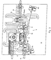
- the Z-shaped rocker 10 is made of a plate-shaped base support 11 worked out, for the assembly of the entire laser device, for example as shown in FIG. 1. Accordingly in Figure 3, the lens 3, the two laser mirrors M2 and M1, the two end mirrors M3 and OC and the laser crystal 5 on the Base support 11 shown assembled. The above is based on the X-folded four-mirror laser resonator 4 explained educated.
- an adjusting spindle 12 is provided, which is in a fixed bearing 13 is supported on the base plate 11 and on a similar to the Z-shaped rocker 10 from the Base support 11 worked out, parallel adjustable, in Top view generally engages U-shaped support member 14, as in 3 is schematically illustrated at 15. In a similar way engages an adjusting spindle 16 on a support element 17 for the Lens 3 at 18, so a parallel shift according to the double arrow 8 to enable.
- the two support elements 14, 17 result in terms of their training and arrangement as well as the Z-shaped rocker 10 more clearly from the top view according to FIG. 4.
- the support elements 14, 17 are also through slot-shaped openings 28, 29 and 30, 31 defined, similarly thin material webs at 32, 33; 34, 35 and 36, 37; 38, 39 for the formation of film hinge joints are left.
- This allows these support elements 14, 17 in Direction of the double arrows 7 and 8 in Fig.1 to 3 using the Spindles 12 and 16 can be adjusted, but it is also there is a slight offset across, but with the present application is no longer disruptive.
- Fig. 5 is the starting position of the only schematic with full lines with straight indicated Z-shaped rocker 10 and with Dashed lines at 10 'illustrate the position adjusted for this.
- the coincidence of the center points M is important because is achieved in that when adjusting the Z-shaped Swing arm 10, its longitudinal arm 27 in the illustration in Fig.5 for example, shifted to the right and at the same time its shifting central axis M is pivoted Focusing mirror M1 during longitudinal displacement and rotation is taken away; since the focusing mirror M1 but around the longitudinally shifted Center M is rotated, this has no disadvantage Effects on the laser beam to be focused, see. d1 or 9, because of the spherical formation of the Mirror surface 43 of the focus point F or F 'on the above Line 40 remains that of the laser beam path 9 in FIGS. 1 and 2 equivalent.
- the component is attached at this focal point F or F ', on which to focus, in this example thus the laser crystal 5, it being evident that the focal point F or F 'corresponding to the shift ⁇ exactly on the preset location of the laser crystal 5 or the Distance between the laser mirrors M1, M2 can be changed, to adjust the stability ranges of the laser.
- the laser beam arm d1 becomes like this with this adjustment 5 can be seen, somewhat parallel to its longitudinal course offset, s. d1 'in Figure 5, but this parallel offset plays not matter, since the associated end mirror M3 is a flat mirror is that only has to be large enough to be able to withstand this parallel offset of the laser beam reflect the laser beam d1 back into itself to be able to.
- the plate-shaped base support 11 can be made of aluminum or an aluminum-magnesium alloy exist, and it can have a thickness of about 15 mm. at the manufacture is made with a corresponding metal plate a thickness of 20 mm, for example, in the grooves to a depth of approx. 15 mm, according to the different Openings 19, 20 and 28, 29, 30, 31, incorporated, in particular milled.
- the remaining thickness of the Plate here of 5 mm, sanded down so that the base support 11 with the openings extending over its entire thickness remains. This increases the mobility of the support elements 14, 17 or the Z-shaped rocker 10 under elastic Deformation of the remaining thin material areas ensured.
Landscapes
- Physics & Mathematics (AREA)
- Electromagnetism (AREA)
- Engineering & Computer Science (AREA)
- Plasma & Fusion (AREA)
- Optics & Photonics (AREA)
- Lasers (AREA)
- Automatic Focus Adjustment (AREA)
- Mounting And Adjusting Of Optical Elements (AREA)
Applications Claiming Priority (3)
| Application Number | Priority Date | Filing Date | Title |
|---|---|---|---|
| AT0088599A AT406989B (de) | 1999-05-18 | 1999-05-18 | Fokussiereinrichtung |
| AT88599 | 1999-05-18 | ||
| PCT/AT2000/000131 WO2000070383A1 (de) | 1999-05-18 | 2000-05-11 | Fokussiereinrichtung |
Publications (2)
| Publication Number | Publication Date |
|---|---|
| EP1181609A1 EP1181609A1 (de) | 2002-02-27 |
| EP1181609B1 true EP1181609B1 (de) | 2003-07-16 |
Family
ID=3502067
Family Applications (1)
| Application Number | Title | Priority Date | Filing Date |
|---|---|---|---|
| EP00929015A Expired - Lifetime EP1181609B1 (de) | 1999-05-18 | 2000-05-11 | Fokussiereinrichtung |
Country Status (9)
| Country | Link |
|---|---|
| US (1) | US6795476B1 (enExample) |
| EP (1) | EP1181609B1 (enExample) |
| JP (1) | JP4554825B2 (enExample) |
| CN (1) | CN1144074C (enExample) |
| AT (1) | AT406989B (enExample) |
| AU (1) | AU4723800A (enExample) |
| BR (1) | BR0010628A (enExample) |
| DE (1) | DE50002916D1 (enExample) |
| WO (1) | WO2000070383A1 (enExample) |
Families Citing this family (3)
| Publication number | Priority date | Publication date | Assignee | Title |
|---|---|---|---|---|
| TW201110489A (en) * | 2009-04-30 | 2011-03-16 | Corning Inc | Folded lasers system |
| JP2017059683A (ja) * | 2015-09-16 | 2017-03-23 | 国立大学法人 東京大学 | レーザー発振器及びレーザー発振器を備えた分光装置、光コヒーレンストモグラフィ装置、非同期光サンプリング装置、長距離絶対距離計測装置、cwレーザー高速高分解能分光装置 |
| CN110666343B (zh) * | 2019-10-31 | 2021-06-25 | 北京半导体专用设备研究所(中国电子科技集团公司第四十五研究所) | 激光转折装置、激光加工光路系统及光路调试方法 |
Family Cites Families (12)
| Publication number | Priority date | Publication date | Assignee | Title |
|---|---|---|---|---|
| US1830308A (en) * | 1928-02-29 | 1931-11-03 | Gustav P Zepke | Extensible support for fixtures |
| FR2442622A1 (fr) * | 1978-06-08 | 1980-06-27 | Aron Rosa Daniele | Appareil de chirurgie ophtalmologique |
| US4661958A (en) * | 1983-05-06 | 1987-04-28 | Coherent, Inc. | Laser |
| US4674097A (en) * | 1986-01-14 | 1987-06-16 | Cooper Lasersonics, Inc. | Distributed-feedback dye laser |
| DE3814829A1 (de) | 1987-05-23 | 1988-12-01 | Teldix Gmbh | Anordnung zur verdrehung einer flaeche |
| US4922501A (en) | 1987-09-30 | 1990-05-01 | Spectra Physics, Inc. | Mirror translation apparatus for altering focal point position in a laser |
| CA1278716C (en) * | 1987-12-14 | 1991-01-08 | Tom Keightley | Mirror assembly |
| US5025446A (en) * | 1988-04-01 | 1991-06-18 | Laserscope | Intra-cavity beam relay for optical harmonic generation |
| US4930493A (en) * | 1988-05-09 | 1990-06-05 | Sallis Daniel V | Multi-lever rim-drive heliostat |
| US5253189A (en) * | 1989-06-13 | 1993-10-12 | Schlumberger Technologies, Inc. | Qualitative kinematics |
| US6298076B1 (en) * | 1999-03-05 | 2001-10-02 | Coherent, Inc. | High-power external-cavity optically-pumped semiconductor lasers |
| US6414752B1 (en) * | 1999-06-18 | 2002-07-02 | Kla-Tencor Technologies Corporation | Method and apparatus for scanning, stitching, and damping measurements of a double-sided metrology inspection tool |
-
1999
- 1999-05-18 AT AT0088599A patent/AT406989B/de not_active IP Right Cessation
-
2000
- 2000-05-11 CN CNB008076316A patent/CN1144074C/zh not_active Expired - Fee Related
- 2000-05-11 AU AU47238/00A patent/AU4723800A/en not_active Abandoned
- 2000-05-11 WO PCT/AT2000/000131 patent/WO2000070383A1/de not_active Ceased
- 2000-05-11 US US09/979,691 patent/US6795476B1/en not_active Expired - Lifetime
- 2000-05-11 JP JP2000618766A patent/JP4554825B2/ja not_active Expired - Fee Related
- 2000-05-11 EP EP00929015A patent/EP1181609B1/de not_active Expired - Lifetime
- 2000-05-11 DE DE50002916T patent/DE50002916D1/de not_active Expired - Lifetime
- 2000-05-11 BR BR0010628-3A patent/BR0010628A/pt not_active IP Right Cessation
Also Published As
| Publication number | Publication date |
|---|---|
| CN1350656A (zh) | 2002-05-22 |
| ATA88599A (de) | 2000-03-15 |
| WO2000070383A1 (de) | 2000-11-23 |
| AT406989B (de) | 2000-11-27 |
| CN1144074C (zh) | 2004-03-31 |
| DE50002916D1 (de) | 2003-08-21 |
| US6795476B1 (en) | 2004-09-21 |
| JP2002544559A (ja) | 2002-12-24 |
| EP1181609A1 (de) | 2002-02-27 |
| AU4723800A (en) | 2000-12-05 |
| JP4554825B2 (ja) | 2010-09-29 |
| BR0010628A (pt) | 2002-02-19 |
Similar Documents
| Publication | Publication Date | Title |
|---|---|---|
| DE2656115A1 (de) | Strahlsteuervorrichtung der spiegelbauart | |
| DE19955599B4 (de) | Laser mit Wellenlängenumwandlung und Bearbeitungsvorrichtung mit einem solchen Laser | |
| DE102009025309B4 (de) | Kinematischer Halter | |
| EP2973980B1 (de) | Anordnung für einen ultraschallmotor | |
| DE1810302A1 (de) | Vorrichtung zur Halterung eines optischen Gliedes | |
| WO2003065108A1 (de) | Federscharnier | |
| EP1181609B1 (de) | Fokussiereinrichtung | |
| DE1622869C3 (de) | Scharnier zum gelenkigen Verbinden einer Brillenfassung mit einem Tragbügel | |
| DE69819380T2 (de) | Federscharnier | |
| EP0301526B1 (de) | Festkörperlaser-Stab | |
| DE3644049A1 (de) | Justiervorrichtung fuer ein optisches element | |
| EP0170722B1 (de) | Brille mit einer Befestigungsvorrichtung | |
| WO2003050586A2 (de) | Spiegelfacette und facettenspiegel | |
| DE3786568T2 (de) | Scharniervorrichtung, insbesondere für Brillen. | |
| DE102022107324B4 (de) | Laserbearbeitungskopf mit Auslenkvorrichtungen | |
| DE3629438C2 (enExample) | ||
| DE4003578C1 (en) | Dry shaver with spring-loaded blade assembly - comprising two blocks in parallel with intermediate and edge support webs | |
| DE69304639T2 (de) | Verformbarer spiegel und korrespondierende lasereinrichtung | |
| WO2023072899A2 (de) | Vorrichtung und verfahren zum ausrichten der position eines optischen elements und kurzpulslasersystem | |
| EP1647370B1 (de) | Gelenkarmroboter mit ein Teleskop aufweisender integrierter Laserstrahlführung | |
| DE2638964C3 (de) | Sägegatter | |
| EP1395859B1 (de) | Laserjustierbarer Aktor, optisches Bauelement und Justierverfahren | |
| DE10060111C1 (de) | Optische Ablenkvorrichtung | |
| DE202010007985U1 (de) | Optik-Halter | |
| DE4334177C1 (de) | Amboß-Gehrungsschere mit Klingenaufnahme |
Legal Events
| Date | Code | Title | Description |
|---|---|---|---|
| PUAI | Public reference made under article 153(3) epc to a published international application that has entered the european phase |
Free format text: ORIGINAL CODE: 0009012 |
|
| 17P | Request for examination filed |
Effective date: 20011029 |
|
| AK | Designated contracting states |
Kind code of ref document: A1 Designated state(s): AT BE CH CY DE DK ES FI FR GB GR IE IT LI LU MC NL PT SE |
|
| AX | Request for extension of the european patent |
Free format text: AL;LT;LV;MK;RO;SI |
|
| GRAH | Despatch of communication of intention to grant a patent |
Free format text: ORIGINAL CODE: EPIDOS IGRA |
|
| GRAH | Despatch of communication of intention to grant a patent |
Free format text: ORIGINAL CODE: EPIDOS IGRA |
|
| GRAA | (expected) grant |
Free format text: ORIGINAL CODE: 0009210 |
|
| AK | Designated contracting states |
Designated state(s): CH DE FR GB IT LI NL |
|
| REG | Reference to a national code |
Ref country code: GB Ref legal event code: FG4D Free format text: NOT ENGLISH |
|
| REG | Reference to a national code |
Ref country code: CH Ref legal event code: EP Ref country code: CH Ref legal event code: NV Representative=s name: ROTTMANN, ZIMMERMANN + PARTNER AG |
|
| REG | Reference to a national code |
Ref country code: IE Ref legal event code: FG4D Free format text: GERMAN |
|
| REF | Corresponds to: |
Ref document number: 50002916 Country of ref document: DE Date of ref document: 20030821 Kind code of ref document: P |
|
| LTIE | Lt: invalidation of european patent or patent extension |
Effective date: 20030716 |
|
| GBT | Gb: translation of ep patent filed (gb section 77(6)(a)/1977) |
Effective date: 20031210 |
|
| REG | Reference to a national code |
Ref country code: IE Ref legal event code: FD4D |
|
| ET | Fr: translation filed | ||
| PLBE | No opposition filed within time limit |
Free format text: ORIGINAL CODE: 0009261 |
|
| STAA | Information on the status of an ep patent application or granted ep patent |
Free format text: STATUS: NO OPPOSITION FILED WITHIN TIME LIMIT |
|
| 26N | No opposition filed |
Effective date: 20040419 |
|
| PGFP | Annual fee paid to national office [announced via postgrant information from national office to epo] |
Ref country code: IT Payment date: 20060531 Year of fee payment: 7 |
|
| PGFP | Annual fee paid to national office [announced via postgrant information from national office to epo] |
Ref country code: NL Payment date: 20070515 Year of fee payment: 8 |
|
| PG25 | Lapsed in a contracting state [announced via postgrant information from national office to epo] |
Ref country code: NL Free format text: LAPSE BECAUSE OF NON-PAYMENT OF DUE FEES Effective date: 20081201 |
|
| PG25 | Lapsed in a contracting state [announced via postgrant information from national office to epo] |
Ref country code: IT Free format text: LAPSE BECAUSE OF NON-PAYMENT OF DUE FEES Effective date: 20070511 |
|
| REG | Reference to a national code |
Ref country code: CH Ref legal event code: PFA Owner name: FEMTOLASERS PRODUKTIONS GMBH Free format text: FEMTOLASERS PRODUKTIONS GMBH#KLEINENGERSDORFERSTRASSE 24#2100 KORNEUBURG (AT) -TRANSFER TO- FEMTOLASERS PRODUKTIONS GMBH#KLEINENGERSDORFERSTRASSE 24#2100 KORNEUBURG (AT) |
|
| REG | Reference to a national code |
Ref country code: FR Ref legal event code: PLFP Year of fee payment: 17 |
|
| PGFP | Annual fee paid to national office [announced via postgrant information from national office to epo] |
Ref country code: GB Payment date: 20160519 Year of fee payment: 17 Ref country code: CH Payment date: 20160526 Year of fee payment: 17 |
|
| PGFP | Annual fee paid to national office [announced via postgrant information from national office to epo] |
Ref country code: FR Payment date: 20160523 Year of fee payment: 17 |
|
| PGFP | Annual fee paid to national office [announced via postgrant information from national office to epo] |
Ref country code: DE Payment date: 20160722 Year of fee payment: 17 |
|
| REG | Reference to a national code |
Ref country code: CH Ref legal event code: PCAR Free format text: NEW ADDRESS: GARTENSTRASSE 28 A, 5400 BADEN (CH) |
|
| REG | Reference to a national code |
Ref country code: DE Ref legal event code: R082 Ref document number: 50002916 Country of ref document: DE |
|
| REG | Reference to a national code |
Ref country code: DE Ref legal event code: R119 Ref document number: 50002916 Country of ref document: DE |
|
| REG | Reference to a national code |
Ref country code: CH Ref legal event code: PL |
|
| GBPC | Gb: european patent ceased through non-payment of renewal fee |
Effective date: 20170511 |
|
| PG25 | Lapsed in a contracting state [announced via postgrant information from national office to epo] |
Ref country code: CH Free format text: LAPSE BECAUSE OF NON-PAYMENT OF DUE FEES Effective date: 20170531 Ref country code: LI Free format text: LAPSE BECAUSE OF NON-PAYMENT OF DUE FEES Effective date: 20170531 |
|
| REG | Reference to a national code |
Ref country code: FR Ref legal event code: ST Effective date: 20180131 |
|
| PG25 | Lapsed in a contracting state [announced via postgrant information from national office to epo] |
Ref country code: GB Free format text: LAPSE BECAUSE OF NON-PAYMENT OF DUE FEES Effective date: 20170511 Ref country code: DE Free format text: LAPSE BECAUSE OF NON-PAYMENT OF DUE FEES Effective date: 20171201 |
|
| PG25 | Lapsed in a contracting state [announced via postgrant information from national office to epo] |
Ref country code: FR Free format text: LAPSE BECAUSE OF NON-PAYMENT OF DUE FEES Effective date: 20170531 |