EP1181609B1 - Focusing device - Google Patents
Focusing device Download PDFInfo
- Publication number
- EP1181609B1 EP1181609B1 EP00929015A EP00929015A EP1181609B1 EP 1181609 B1 EP1181609 B1 EP 1181609B1 EP 00929015 A EP00929015 A EP 00929015A EP 00929015 A EP00929015 A EP 00929015A EP 1181609 B1 EP1181609 B1 EP 1181609B1
- Authority
- EP
- European Patent Office
- Prior art keywords
- focussing
- shaped
- arrangement according
- rocking member
- laser
- Prior art date
- Legal status (The legal status is an assumption and is not a legal conclusion. Google has not performed a legal analysis and makes no representation as to the accuracy of the status listed.)
- Expired - Lifetime
Links
- 239000013078 crystal Substances 0.000 claims description 17
- 239000000463 material Substances 0.000 claims description 17
- 238000006073 displacement reaction Methods 0.000 claims description 4
- 229910052782 aluminium Inorganic materials 0.000 claims description 3
- XAGFODPZIPBFFR-UHFFFAOYSA-N aluminium Chemical compound [Al] XAGFODPZIPBFFR-UHFFFAOYSA-N 0.000 claims description 3
- 229910045601 alloy Inorganic materials 0.000 claims description 2
- 239000000956 alloy Substances 0.000 claims description 2
- 238000004519 manufacturing process Methods 0.000 description 8
- 239000010936 titanium Substances 0.000 description 4
- 201000009310 astigmatism Diseases 0.000 description 3
- 230000015572 biosynthetic process Effects 0.000 description 3
- 239000000969 carrier Substances 0.000 description 3
- 238000010276 construction Methods 0.000 description 3
- 238000010586 diagram Methods 0.000 description 3
- RTAQQCXQSZGOHL-UHFFFAOYSA-N Titanium Chemical compound [Ti] RTAQQCXQSZGOHL-UHFFFAOYSA-N 0.000 description 2
- 230000000694 effects Effects 0.000 description 2
- 230000005489 elastic deformation Effects 0.000 description 2
- 229910052594 sapphire Inorganic materials 0.000 description 2
- 239000010980 sapphire Substances 0.000 description 2
- 238000003860 storage Methods 0.000 description 2
- 229910052719 titanium Inorganic materials 0.000 description 2
- 238000012549 training Methods 0.000 description 2
- 229910000861 Mg alloy Inorganic materials 0.000 description 1
- 229910000831 Steel Inorganic materials 0.000 description 1
- SNAAJJQQZSMGQD-UHFFFAOYSA-N aluminum magnesium Chemical compound [Mg].[Al] SNAAJJQQZSMGQD-UHFFFAOYSA-N 0.000 description 1
- 150000001875 compounds Chemical class 0.000 description 1
- 238000005520 cutting process Methods 0.000 description 1
- 230000001419 dependent effect Effects 0.000 description 1
- 238000011161 development Methods 0.000 description 1
- 230000018109 developmental process Effects 0.000 description 1
- 238000009760 electrical discharge machining Methods 0.000 description 1
- 230000002349 favourable effect Effects 0.000 description 1
- 229910052751 metal Inorganic materials 0.000 description 1
- 239000002184 metal Substances 0.000 description 1
- 238000000034 method Methods 0.000 description 1
- 238000004513 sizing Methods 0.000 description 1
- 239000010959 steel Substances 0.000 description 1
- 238000013519 translation Methods 0.000 description 1
- XLYOFNOQVPJJNP-UHFFFAOYSA-N water Substances O XLYOFNOQVPJJNP-UHFFFAOYSA-N 0.000 description 1
Images


Classifications
-
- H—ELECTRICITY
- H01—ELECTRIC ELEMENTS
- H01S—DEVICES USING THE PROCESS OF LIGHT AMPLIFICATION BY STIMULATED EMISSION OF RADIATION [LASER] TO AMPLIFY OR GENERATE LIGHT; DEVICES USING STIMULATED EMISSION OF ELECTROMAGNETIC RADIATION IN WAVE RANGES OTHER THAN OPTICAL
- H01S3/00—Lasers, i.e. devices using stimulated emission of electromagnetic radiation in the infrared, visible or ultraviolet wave range
- H01S3/05—Construction or shape of optical resonators; Accommodation of active medium therein; Shape of active medium
- H01S3/08—Construction or shape of optical resonators or components thereof
- H01S3/086—One or more reflectors having variable properties or positions for initial adjustment of the resonator
-
- H—ELECTRICITY
- H01—ELECTRIC ELEMENTS
- H01S—DEVICES USING THE PROCESS OF LIGHT AMPLIFICATION BY STIMULATED EMISSION OF RADIATION [LASER] TO AMPLIFY OR GENERATE LIGHT; DEVICES USING STIMULATED EMISSION OF ELECTROMAGNETIC RADIATION IN WAVE RANGES OTHER THAN OPTICAL
- H01S3/00—Lasers, i.e. devices using stimulated emission of electromagnetic radiation in the infrared, visible or ultraviolet wave range
- H01S3/02—Constructional details
- H01S3/025—Constructional details of solid state lasers, e.g. housings or mountings
-
- H—ELECTRICITY
- H01—ELECTRIC ELEMENTS
- H01S—DEVICES USING THE PROCESS OF LIGHT AMPLIFICATION BY STIMULATED EMISSION OF RADIATION [LASER] TO AMPLIFY OR GENERATE LIGHT; DEVICES USING STIMULATED EMISSION OF ELECTROMAGNETIC RADIATION IN WAVE RANGES OTHER THAN OPTICAL
- H01S3/00—Lasers, i.e. devices using stimulated emission of electromagnetic radiation in the infrared, visible or ultraviolet wave range
- H01S3/05—Construction or shape of optical resonators; Accommodation of active medium therein; Shape of active medium
- H01S3/08—Construction or shape of optical resonators or components thereof
- H01S3/081—Construction or shape of optical resonators or components thereof comprising three or more reflectors
- H01S3/0813—Configuration of resonator
- H01S3/0816—Configuration of resonator having 4 reflectors, e.g. Z-shaped resonators
-
- H—ELECTRICITY
- H01—ELECTRIC ELEMENTS
- H01S—DEVICES USING THE PROCESS OF LIGHT AMPLIFICATION BY STIMULATED EMISSION OF RADIATION [LASER] TO AMPLIFY OR GENERATE LIGHT; DEVICES USING STIMULATED EMISSION OF ELECTROMAGNETIC RADIATION IN WAVE RANGES OTHER THAN OPTICAL
- H01S3/00—Lasers, i.e. devices using stimulated emission of electromagnetic radiation in the infrared, visible or ultraviolet wave range
- H01S3/10—Controlling the intensity, frequency, phase, polarisation or direction of the emitted radiation, e.g. switching, gating, modulating or demodulating
- H01S3/11—Mode locking; Q-switching; Other giant-pulse techniques, e.g. cavity dumping
- H01S3/1106—Mode locking
- H01S3/1112—Passive mode locking
Definitions
- the invention relates to a focusing device, in particular for laser devices, according to the introductory part of claim 1 or a laser device with such Focusing.
- Focusing devices are often used in laser devices used, for an exact focus setting an exact Adjustment of the respective focusing mirror is required.
- conventional focusing devices are used as carriers for the Focusing mirror sliding tables (translation or measuring tables) used with plain or roller bearings; the effort for this
- constructions are extraordinarily high, and always existing bearing play leads to reduced rigidity of the element.
- the object of the invention is therefore to create a focusing device of the type mentioned at the beginning, which is characterized by a simple and stable structure, and the one easy manufacture is accessible.
- the invention provides a focusing device as defined in claim 1. advantageous Refinements and developments are in the dependent claims specified.
- the invention further provides a laser device with a focusing device according to the invention, where advantageous refinements thereof are the subject of Claims 14 and 15 are.
- a Z-shaped one Rocker provided, which is dimensioned and arranged so that - seen in plan view - the center of the vibrating Longitudinal arm coincides with the center of the circle that the describes the spherical mirror surface of the focusing mirror.
- This twisting of the Focusing mirror takes place around its center of curvature, i.e. the focusing mirror is "along its mirror surface twisted "so that this twisting does not distract the user focused beam.
- the focused beam runs therefore continue according to a predetermined straight line, only the Focus point is adjusted along this straight line.
- the center of curvature of the Mirror surface of the focusing mirror on the bisector between the incident beam and the line which shifted the focus of the focusing mirror during adjustment becomes.
- the focusing device according to the invention can be advantageous used in laser devices, especially in laser resonators as in laser devices of the type WO 98/10494 A described.
- the invention also with astigmatism-compensated laser resonators, such as in Herwig W. Kogelnik, Erich P. Ippen, Andrew Dienes, Charles Shank: “Astigmatically Compensated Cavities for CW Dye Lasers", Journal of Quantum Electronics, QE-8, No.3, March 1972, pp.
- the laser medium namely a laser crystal, in particular a Ti: S (titanium sapphire) laser crystal, in Form of a plane-parallel plate, at a Brewster angle to the laser beam arranged, and the laser beam is in the laser medium focused with the help of focusing mirrors.
- a laser crystal in particular a Ti: S (titanium sapphire) laser crystal
- Ti: S (titanium sapphire) laser crystal in Form of a plane-parallel plate
- the present focusing device generally applicable to any arrangement where a light beam or laser beam with the help of a concave mirror should be focused, and where to adjust the focus point exactly is.
- the thin material areas or webs that the film hinges form preferably have a thickness of about 0.3 mm to 0.5 mm, in particular about 0.4 mm.
- a Sizing is the desired elastic flexibility Z-shaped swing arm ensures without breaking of thin material areas is coming. It has been surprising demonstrated that thicker material webs break more easily than such thin material areas with a thickness of the order of magnitude of a few tenths of a millimeter.
- the plate-shaped base support and the Z-shaped Swing arm made of aluminum or an AlMg alloy consist.
- the longitudinal arm of the Z-shaped Swing arm has a cranked course in plan view.
- the present invention is advantageous used in laser devices, and accordingly is one particularly advantageous application given that in focus of the focusing mirror, outside the Z-shaped rocker Laser medium, e.g. a laser crystal is arranged.
- the Z-shaped Swing arm can be one of the focusing mirrors of a laser resonator wear.
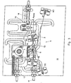
- FIG. 1 schematically illustrates a laser device 1, in which a pump beam 2 is X-folded via a lens 3 Laser resonator 4 is supplied.
- the label "X-folded” stems from the fact that two are directed towards end mirrors M3 and OC Laser beam arms d1, d2 cross each other and thus form an "X”.
- the laser resonator 4 is also equipped with two laser mirrors M1, M2, between which a Ti: S (titanium sapphire) crystal is used as the laser medium 5 is arranged. It refers to a plane-parallel body, a parallelepiped, which for example is optically non-linear and forms a Kerr element.
- This laser crystal 5 is in the so-called. Brewster angle arranged to minimize losses, and in this laser crystal 5 the laser beam is focused. By focusing on the Laser crystal 5 arranged at Brewster angle becomes an astigmatism introduced, however, by tilting the focusing mirror M1, M2 can be compensated, cf. the angles ⁇ 1 and ⁇ 2 in Fig.1.
- the two focusing mirrors one is a mirror, M2, the other mirror, M1, is used to adjust the Focus point in the laser crystal 5 adjusted exactly what in Fig.1 with the double arrow at 6 is illustrated.
- the laser crystal 5 and the lens 3 in the course of assembly can be adjusted linearly, as by further double arrows 7, 8 in Fig.1 is indicated; these adjustments are shown below 3 to 5 will be explained in more detail.
- a Z-folded is in a similar scheme
- the laser resonators 4 explained with reference to FIGS. 1 and 2 are only examples of the application of the above focusing device to understand, and the present focusing device can also be used, for example, with three-mirror resonators or with multi-mirror resonators (with more than four mirrors) as well as in general when adjusting from to Focusing spherical concave mirror used become.
- a substantially in plan view Z-shaped rocker arm 10 used in a specific, Arranged and dimensioned below in more detail is to move in spite of twisting during an adjustment Maintain the predetermined orientation of the beam 9 in the longitudinal direction and thus only the focal point F (see Fig. 5) by adjustment of the focusing mirror M1.
- the Z-shaped rocker 10 is made of a plate-shaped base support 11 worked out, for the assembly of the entire laser device, for example as shown in FIG. 1. Accordingly in Figure 3, the lens 3, the two laser mirrors M2 and M1, the two end mirrors M3 and OC and the laser crystal 5 on the Base support 11 shown assembled. The above is based on the X-folded four-mirror laser resonator 4 explained educated.
- an adjusting spindle 12 is provided, which is in a fixed bearing 13 is supported on the base plate 11 and on a similar to the Z-shaped rocker 10 from the Base support 11 worked out, parallel adjustable, in Top view generally engages U-shaped support member 14, as in 3 is schematically illustrated at 15. In a similar way engages an adjusting spindle 16 on a support element 17 for the Lens 3 at 18, so a parallel shift according to the double arrow 8 to enable.
- the two support elements 14, 17 result in terms of their training and arrangement as well as the Z-shaped rocker 10 more clearly from the top view according to FIG. 4.
- the support elements 14, 17 are also through slot-shaped openings 28, 29 and 30, 31 defined, similarly thin material webs at 32, 33; 34, 35 and 36, 37; 38, 39 for the formation of film hinge joints are left.
- This allows these support elements 14, 17 in Direction of the double arrows 7 and 8 in Fig.1 to 3 using the Spindles 12 and 16 can be adjusted, but it is also there is a slight offset across, but with the present application is no longer disruptive.
- Fig. 5 is the starting position of the only schematic with full lines with straight indicated Z-shaped rocker 10 and with Dashed lines at 10 'illustrate the position adjusted for this.
- the coincidence of the center points M is important because is achieved in that when adjusting the Z-shaped Swing arm 10, its longitudinal arm 27 in the illustration in Fig.5 for example, shifted to the right and at the same time its shifting central axis M is pivoted Focusing mirror M1 during longitudinal displacement and rotation is taken away; since the focusing mirror M1 but around the longitudinally shifted Center M is rotated, this has no disadvantage Effects on the laser beam to be focused, see. d1 or 9, because of the spherical formation of the Mirror surface 43 of the focus point F or F 'on the above Line 40 remains that of the laser beam path 9 in FIGS. 1 and 2 equivalent.
- the component is attached at this focal point F or F ', on which to focus, in this example thus the laser crystal 5, it being evident that the focal point F or F 'corresponding to the shift ⁇ exactly on the preset location of the laser crystal 5 or the Distance between the laser mirrors M1, M2 can be changed, to adjust the stability ranges of the laser.
- the laser beam arm d1 becomes like this with this adjustment 5 can be seen, somewhat parallel to its longitudinal course offset, s. d1 'in Figure 5, but this parallel offset plays not matter, since the associated end mirror M3 is a flat mirror is that only has to be large enough to be able to withstand this parallel offset of the laser beam reflect the laser beam d1 back into itself to be able to.
- the plate-shaped base support 11 can be made of aluminum or an aluminum-magnesium alloy exist, and it can have a thickness of about 15 mm. at the manufacture is made with a corresponding metal plate a thickness of 20 mm, for example, in the grooves to a depth of approx. 15 mm, according to the different Openings 19, 20 and 28, 29, 30, 31, incorporated, in particular milled.
- the remaining thickness of the Plate here of 5 mm, sanded down so that the base support 11 with the openings extending over its entire thickness remains. This increases the mobility of the support elements 14, 17 or the Z-shaped rocker 10 under elastic Deformation of the remaining thin material areas ensured.
Description
Die Erfindung betrifft eine Fokussiereinrichtung, insbesondere für Laservorrichtungen, gemäß dem einleitenden Teil von Anspruch 1 bzw. eine Laservorrichtung mit einer solchen Fokussiereinrichtung.The invention relates to a focusing device, in particular for laser devices, according to the introductory part of claim 1 or a laser device with such Focusing.
Fokussiereinrichtungen werden vielfach bei Laservorrichtungen verwendet, wobei für eine exakte Fokuseinstellung eine genaue Justierung des jeweiligen Fokussierspiegels erforderlich ist. Bei herkömmlichen Fokussiereinrichtungen werden als Träger für den Fokussierspiegel Verschiebetische (Translations- oder Messtische) mit Gleit- bzw. Wälzlagern eingesetzt; der Aufwand für diese Konstruktionen ist jedoch außerordentlich hoch, und ein immer vorhandenes Lagerspiel führt zu einer verminderten Steifigkeit des Elements.Focusing devices are often used in laser devices used, for an exact focus setting an exact Adjustment of the respective focusing mirror is required. at conventional focusing devices are used as carriers for the Focusing mirror sliding tables (translation or measuring tables) used with plain or roller bearings; the effort for this However, constructions are extraordinarily high, and always existing bearing play leads to reduced rigidity of the element.
Aufgabe der Erfindung ist daher die Schaffung einer Fokussiereinrichtung der eingangs angeführten Art, die sich durch einen einfachen und stabilen Aufbau auszeichnet, und die einer einfachen Herstellung zugänglich ist.The object of the invention is therefore to create a focusing device of the type mentioned at the beginning, which is characterized by a simple and stable structure, and the one easy manufacture is accessible.
Zur Lösung dieser Aufgabe sieht die Erfindung eine Fokussiereinrichtung
wie in Anspruch 1 definiert vor. Vorteilhafte
Ausgestaltungen und Weiterbildungen sind in den abhängigen Ansprüchen
angegeben. Weiters sieht die Erfindung eine Laservorrichtung
mit einer erfindungsgemäßen Fokussiereinrichtung vor,
wobei vorteilhafte Ausgestaltungen hievon Gegenstand der
Ansprüche 14 und 15 sind.To achieve this object, the invention provides a focusing device
as defined in claim 1. advantageous
Refinements and developments are in the dependent claims
specified. The invention further provides a laser device
with a focusing device according to the invention,
where advantageous refinements thereof are the subject of
Bei der vorliegenden Fokussiereinrichtung ist eine Z-förmige Schwinge vorgesehen, die so dimensioniert und angeordnet ist, dass - in Draufsicht gesehen - der Mittelpunkt des schwingenden Längsarmes mit dem Mittelpunkt des Kreises zusammenfällt, den die sphärische Spiegelfläche des Fokussierspiegels beschreibt. Bei einer translatorischen Verstellung der Z-förmigen Schwinge wird diese auch um die durch ihren geometrischen Mittelpunkt verlaufende Achse verdreht, was zu einer entsprechenden Verdrehung des Fokussierspiegels führt. Diese Verdrehung des Fokussierspiegels erfolgt jedoch um dessen Krümmungsmittelpunkt, d.h. der Fokussierspiegel wird "entlang seiner Spiegelfläche verdreht", so dass diese Verdrehung zu keiner Ablenkung des fokussierten Strahles führt. Der fokussierte Strahl verläuft daher weiterhin gemäß einer vorgegebenen Geraden, wobei nur der Fokuspunkt entlang dieser Geraden verstellt wird. Hierbei ist auch bevorzugt vorgesehen, dass der Krümmungsmittelpunkt der Spiegelfläche des Fokussierspiegels auf der Winkelhalbierenden zwischen dem einfallenden Strahl und der Linie liegt, entlang der der Fokus des Fokussierspiegels bei der Verstellung verschoben wird.In the present focusing device, there is a Z-shaped one Rocker provided, which is dimensioned and arranged so that - seen in plan view - the center of the vibrating Longitudinal arm coincides with the center of the circle that the describes the spherical mirror surface of the focusing mirror. at a translational adjustment of the Z-shaped rocker arm this also around the one running through its geometric center Axis twisted, resulting in a corresponding Twisting of the focusing mirror leads. This twisting of the Focusing mirror, however, takes place around its center of curvature, i.e. the focusing mirror is "along its mirror surface twisted "so that this twisting does not distract the user focused beam. The focused beam runs therefore continue according to a predetermined straight line, only the Focus point is adjusted along this straight line. Here is also preferably provided that the center of curvature of the Mirror surface of the focusing mirror on the bisector between the incident beam and the line which shifted the focus of the focusing mirror during adjustment becomes.
Die erfindungsgemäße Fokussiereinrichtung kann mit Vorteil bei Laservorrichtungen, insbesondere bei Laserresonatoren, eingesetzt werden, wie etwa bei Laservorrichtungen der Art, wie in der WO 98/10494 A beschrieben. Insbesondere kann die Erfindung auch bei Astigmatismus-kompensierten Laserresonatoren, etwa wie in Herwig W. Kogelnik, Erich P. Ippen, Andrew Dienes, Charles Shank: "Astigmatically Compensated Cavities for CW Dye Lasers", Journal of Quantum Electronics, QE-8, No.3, März 1972, S. 373-379, beschrieben, eingesetzt werden; bei einer derartigen Laserresonator-Anordnung ist das Lasermedium, nämlich ein Laserkristall, insbesondere ein Ti:S-(Titan-Saphir-)Laserkristall, in Form einer planparallelen Platte, im Brewster-Winkel zum Laserstrahl angeordnet, und der Laserstrahl wird in das Lasermedium mit Hilfe von Fokussierspiegeln fokussiert. Durch die Fokussierung in das im Brewster-Winkel angeordnete Lasermedium wird jedoch ein Astigmatismus eingeführt, und dieser wird durch ein Verkippen der Fokussierspiegel kompensiert.The focusing device according to the invention can be advantageous used in laser devices, especially in laser resonators as in laser devices of the type WO 98/10494 A described. In particular, the invention also with astigmatism-compensated laser resonators, such as in Herwig W. Kogelnik, Erich P. Ippen, Andrew Dienes, Charles Shank: "Astigmatically Compensated Cavities for CW Dye Lasers", Journal of Quantum Electronics, QE-8, No.3, March 1972, pp. 373-379, described, used; with such a laser resonator arrangement is the laser medium, namely a laser crystal, in particular a Ti: S (titanium sapphire) laser crystal, in Form of a plane-parallel plate, at a Brewster angle to the laser beam arranged, and the laser beam is in the laser medium focused with the help of focusing mirrors. By focusing into the laser medium arranged at Brewster angle an astigmatism is introduced, and this is caused by a Tilting of the focusing mirror compensated.
Grundsätzlich ist jedoch die vorliegende Fokussiereinrichtung ganz allgemein bei beliebigen Anordnungen einsetzbar, wo ein Lichtstrahl bzw. Laserstrahl mit Hilfe eines Hohlspiegels fokussiert werden soll, und wo der Fokuspunkt genau einzujustieren ist.Basically, however, the present focusing device generally applicable to any arrangement where a light beam or laser beam with the help of a concave mirror should be focused, and where to adjust the focus point exactly is.
Für die Ausbildung des Trägers und seine Lagerung wäre beispielsweise eine Bauweise mit einem Block (als Längsarm der Schwinge) und mit Flachstahlfedern (als "gelenkige" Querarme) denkbar. Auch sind Ausführungen denkbar, gemäß welchen starre Querarme gelenkig mit dem Längsarm verbunden sowie - mit ihren vom Längsarm abgewandten Enden - schwenkbar gelagert sind. Im Hinblick auf eine einfache Herstellung ist es vorteilhaft, wenn die vom Längsträger abgewandten Enden der Querarme der Z- förmigen Schwinge mit einem Basisträger über dünne Materialbereiche in der Art eines Filmscharnier-Gelenks verbunden sind. Der Basisträger ist dabei vorzugsweise plattenförmig ausgebildet.For example, for the formation of the carrier and its storage a construction with a block (as a longitudinal arm of the Swingarm) and with flat steel springs (as "articulated" cross arms) conceivable. There are also conceivable designs according to which rigid ones Cross arms articulated to the longitudinal arm and - with their Ends facing away from the longitudinal arm - are pivotally mounted. in the With a view to simple manufacture, it is advantageous if the ends of the cross arms of the Z-shaped facing away from the side member Swing with a base beam over thin areas of material are connected in the manner of a film hinge joint. The base bearer is preferably plate-shaped.
In entsprechender Weise ist es günstig, wenn die Querarme der Z-förmigen Schwinge mit dem Längsarm über dünne Materialbereiche in der Art eines Filmscharnier-Gelenks verbunden sind.In a corresponding manner, it is advantageous if the cross arms the Z-shaped swing arm with the longitudinal arm over thin material areas are connected in the manner of a film hinge joint.
Bei der vorliegenden Fokussiereinrichtung wird somit bevorzugt auf eine an sich bereits bekannte Technik von über elastisch deformierbare Lagerteile gelagerten Trägern zurückgegriffen, wie sie unter der Bezeichnung "Flexure Arrangement" in einem Katalog von Melles Griot, S. 368/369, beschrieben ist. Dabei werden bei den bekannten Anordnungen die Träger unter elastischer Verformung ihrer Lagerteile verstellt, wobei es aber zu einem für die vorliegenden Anwendungen unerwünschten Parallelversatz kommt. Um einen solchen Parallelversatz zu vermeiden, wurde auch ein - allerdings sehr komplizierter - Aufbau, "Compound Flexure Arrangement" genannt, vorgeschlagen. Im Vergleich zu dieser Anordnung mit flexibler Mehrfachlagerung ist die vorliegende Z-förmige Schwinge wesentlich einfacher in der Herstellung und überdies auch stabiler im Betrieb.In the present focusing device, preference is therefore given to this to a technique known per se of over elastic deformable bearing parts relied on supported beams, as they are called "Flexure Arrangement" in a catalog by Melles Griot, pp. 368/369. there in the known arrangements, the carriers are more elastic Deformation of their bearing parts adjusted, but it too an undesirable parallel offset for the present applications comes. To avoid such a parallel offset, also became a - albeit very complicated - structure, "Compound Flexure Arrangement ", proposed. In comparison to this arrangement with flexible multiple storage is the present Z-shaped swing arm much easier to manufacture and also more stable in operation.
Im Hinblick auf eine anzustrebende Massenfertigung hat es sich ferner als günstig erwiesen, wenn die Z-förmige Schwinge aus dem plattenförmigen Basisträger durch Anbringung von Durchbrechungen, unter Belassung der dünnen Materialbereiche, herausgearbeitet ist. Bei der Herstellung kann von einer dickeren (z.B. ca. 20 mm dicken) Ausgangsplatte ausgegangen werden, in der die entsprechenden Nuten für die Durchbrechungen über einen Teil der Dicke der Platte (z.B. ca. 15 mm) eingearbeitet, z.B. eingefräst werden. Danach kann die restliche Dicke (z.B. ca. 5 mm) weggeschliffen werden, so dass die den Basisträger samt der Z-förmigen Schwinge bildende Platte, etwa mit einer Dicke von 15 mm, verbleibt. Für das Einarbeiten der Nuten bzw. Durchbrechungen können selbstverständlich auch andere Fertigungsverfahren, wie z.B. Funkenerodieren oder Wasserstrahlschneiden, angewandt werden.With regard to mass production, it has also proved to be favorable if the Z-shaped rocker from the plate-shaped base support by making openings, worked out while leaving the thin material areas is. In the manufacture of a thicker (e.g. approx. 20 mm thick) starting plate, in of the corresponding grooves for the openings over one Part of the thickness of the plate (e.g. approx. 15 mm) incorporated, e.g. be milled. Then the remaining thickness (e.g. approx. 5 mm) are sanded away, so that the base carrier together of the Z-shaped rocker-forming plate, approximately with a thickness of 15 mm remains. For working in the grooves or openings can of course also other manufacturing processes, such as. Spark erosion or water jet cutting, be applied.
Die dünnen Materialbereiche oder -stege, die die Filmscharniere bilden, weisen bevorzugt eine Dicke von ca. 0,3 mm bis 0,5 mm, insbesondere ca. 0,4 mm, auf. Bei einer derartigen Dimensionierung wird die gewünschte elastische Beweglichkeit der Z-förmigen Schwinge sichergestellt, ohne dass es zu einem Bruch der dünnen Materialbereiche kommt. Überraschend hat sich nämlich gezeigt, dass dickere Materialstege leichter brechen als derartige dünne Materialbereiche mit einer Stärke in der Größenordnung von einigen Zehntelmillimetern.The thin material areas or webs that the film hinges form, preferably have a thickness of about 0.3 mm to 0.5 mm, in particular about 0.4 mm. With such a Sizing is the desired elastic flexibility Z-shaped swing arm ensures without breaking of thin material areas is coming. It has been surprising demonstrated that thicker material webs break more easily than such thin material areas with a thickness of the order of magnitude of a few tenths of a millimeter.
Im Hinblick einerseits auf die erforderliche elastische Deformierbarkeit und andererseits die gewünschte Stabilität ist es auch vorteilhaft, wenn der plattenförmige Basisträger und die Z-förmige Schwinge aus Aluminium oder aus einer AlMg-Legierung bestehen.With regard to the necessary elastic deformability and on the other hand it is the desired stability also advantageous if the plate-shaped base support and the Z-shaped Swing arm made of aluminum or an AlMg alloy consist.
Um für die Unterbringung von anderen Komponenten der Fokussiereinrichtung, wie insbesondere jene Komponente, auf die zu fokussieren ist, außerhalb der Z-förmigen Schwinge besser Platz zu schaffen, ist es auch günstig, wenn der Längsarm der Z-förmigen Schwinge einen in Draufsicht gekröpften Verlauf aufweist.In order to accommodate other components of the focusing device, like in particular the component to which focus is better place outside the Z-shaped swing arm to create, it is also convenient if the longitudinal arm of the Z-shaped Swing arm has a cranked course in plan view.
Wie bereits erwähnt wird die vorliegende Erfindung mit Vorteil bei Laservorrichtungen eingesetzt, und demgemäß ist eine besonders vorteilhafte Anwendung dadurch gegeben, dass im Fokus des Fokussierspiegels, außerhalb der Z-förmigen Schwinge, ein Lasermedium, z.B. ein Laserkristall, angeordnet ist. Die Z-förmige Schwinge kann dabei einen der Fokussierspiegel eines Laserresonators tragen.As already mentioned, the present invention is advantageous used in laser devices, and accordingly is one particularly advantageous application given that in focus of the focusing mirror, outside the Z-shaped rocker Laser medium, e.g. a laser crystal is arranged. The Z-shaped Swing arm can be one of the focusing mirrors of a laser resonator wear.
Die Erfindung wird nachstehend anhand von in der Zeichnung
dargestellten besonders bevorzugten Ausführungsbeispielen, auf
die sie jedoch nicht beschränkt sein soll, noch weiter erläutert.
Es zeigen:
In Fig.1 ist schematisch eine Laservorrichtung 1 veranschaulicht,
bei der ein Pumpstrahl 2 über eine Linse 3 einem X-gefalteten
Laserresonator 4 zugeführt wird. Die Bezeichnung "X-gefaltet"
rührt daher, dass zwei zu Endspiegeln M3 bzw. OC gerichtete
Laserstrahlarme d1, d2 einander kreuzen und somit ein "X" bilden.1 schematically illustrates a laser device 1,
in which a
Der Laserresonator 4 ist ferner mit zwei Laserspiegeln M1,
M2 ausgebildet, zwischen denen als Lasermedium ein Ti:S-(Titan-Saphir-)Kristall
5 angeordnet ist. Dabei handelt es sich um
einen planparallelen Körper, ein Parallelepiped, welches beispielsweise
optisch nicht-linear ist und ein Kerr-Element bildet.
Dieser Laserkristall 5 ist im sogen. Brewster-Winkel angeordnet,
um Verluste zu minimieren, und in diesen Laserkristall 5
wird der Laserstrahl fokussiert. Durch die Fokussierung in den
im Brewster-Winkel angeordneten Laserkristall 5 wird ein Astigmatismus
eingeführt, der jedoch durch ein Verkippen der Fokussierspiegel
M1, M2 kompensiert werden kann, vgl. die Winkel β1
und β2 in Fig.1.The
Von den beiden Fokussierspiegeln ist der eine Spiegel, M2,
fest, hingegen wird der andere Spiegel, M1, zur Einstellung des
Fokuspunktes im Laserkristall 5 genau justiert, was in Fig.1 mit
dem Doppelpfeil bei 6 veranschaulicht ist. Im Übrigen können
auch der Laserkristall 5 sowie die Linse 3 im Zuge der Montage
linear verstellt werden, wie durch weitere Doppelpfeile 7, 8 in
Fig.1 angedeutet ist; diese Verstellungen werden nachstehend
anhand der Fig.3 bis 5 noch näher erläutert werden.Of the two focusing mirrors, one is a mirror, M2,
the other mirror, M1, is used to adjust the
Focus point in the
In Fig.2 ist in einem ähnlichen Schema ein Z-gefalteter Vier-Spiegel-Laserresonator gezeigt, bei dem ein Laserstrahl-Arm d2 nach oben und ein Laserstrahl-Arm d1 nach unten abgelenkt wird; diese beiden Arme d1, d2 bilden mit der Verbindung zwischen den Laserspiegeln M1, M2 ein "Z".In Figure 2, a Z-folded is in a similar scheme Four mirror laser resonator shown using a laser beam arm d2 deflected upwards and a laser beam arm d1 downwards becomes; these two arms form d1, d2 with the connection between the laser mirrors M1, M2 a "Z".
Im Übrigen entsprechen die Bauelemente der Laservorrichtung
gemäß Fig.2 jenen gemäß Fig.1, wobei auch die gleichen Bezugszeichen
verwendet wurden, und es kann sich somit eine weitere
Erläuterung erübrigen.Otherwise, the components correspond to the
Die anhand der Fig.1 und 2 erläuterten Laserresonatoren 4
sind nur als Beispiele für die Anwendung der vorstehenden Fokussiereinrichtung
zu verstehen, und die vorliegende Fokussiereinrichtung
kann auch beispielsweise bei Drei-Spiegel-Resonatoren
oder aber bei Mehr-Spiegel-Resonatoren (mit mehr als vier Spiegeln)
ebenso wie ganz allgemein bei der Verstellung von zur
Fokussierung verwendeten sphärischen Hohlspiegeln eingesetzt
werden.The
Um den Fokuspunkt des Fokussierspiegels M1 im Laserkristall
5 genau einjustieren zu können bzw. die Stabilitätsbereiche des
Laserresonators 4 für eine stabile Lasertätigkeit zu finden,
muss eine Verstellung des Fokussierspiegels M1 erreicht werden,
bei der der Verlauf des Laserstrahls zwischen diesem Fokussierspiegel
M1 und dem Laserkristall 5 örtlich nicht verschoben
wird. Dieser Laserstrahl-Verlauf ist in Fig.1 und 2 bei 9 angegeben.
Um diese Strahlausrichtung beizubehalten, wurden in der
Vergangenheit aufwendige Verschiebetische als Träger für den
Fokussierspiegel M1 verwendet. Anstattdessen wird nunmehr, wie
aus den Fig.3 bis 5 ersichtlich, eine in Draufsicht im Wesentlichen
Z-förmige Schwinge 10 eingesetzt, die in einer bestimmten,
nachstehend näher erläuterten Weise angeordnet und dimensioniert
ist, um trotz eines Verdrehens bei einer Verstellung in
Längsrichtung die vorgegebene Ausrichtung des Strahls 9 beizubehalten
und somit nur den Fokuspunkt F (s. Fig.5) durch Verstellung
des Fokussierspiegels M1 zu verschieben.Around the focal point of the focusing mirror M1 in the
Die Z-förmige Schwinge 10 ist aus einem plattenförmigen Basisträger
11 herausgearbeitet, der zur Montage der gesamten Laservorrichtung,
beispielsweise gemäß Fig.1, dient. Demgemäß sind
in Fig.3 die Linse 3, die beiden Laserspiegel M2 und M1, die
beiden Endspiegel M3 und OC sowie der Laserkristall 5 auf dem
Basisträger 11 montiert gezeigt. Dabei ist der vorstehend anhand
der Fig.1 erläuterte X-gefaltete Vier-Spiegel-Laserresonator 4
gebildet.The Z-shaped
Zur Verstellung des Halters mit dem Laserkristall 5 gemäß
Doppelpfeil 7 ist eine Stellspindel 12 vorgesehen, die sich in
einem festen Lager 13 auf der Basisplatte 11 abstützt und an
einem in ähnlicher Weise wie die Z-förmige Schwinge 10 aus dem
Basisträger 11 herausgearbeiteten, parallel verstellbaren, in
Draufsicht allgemein U-förmigen Tragelement 14 angreift, wie in
Fig.3 bei 15 schematisch veranschaulicht ist. In ähnlicher Weise
greift eine Stellspindel 16 an einem Tragelement 17 für die
Linse 3 bei 18 an, um so eine Parallelverschiebung gemäß Doppelpfeil
8 zu ermöglichen.To adjust the holder with the
Die beiden Tragelemente 14, 17 ergeben sich hinsichtlich
ihrer Ausbildung und Anordnung ebenso wie die Z-förmige Schwinge
10 deutlicher aus der Draufsicht gemäß Fig.4.The two
Im plattenförmigen Basisträger 11 sind, um die Z-förmige
Schwinge 10 zu erhalten, zwei in ihrem Verlauf aus Fig.4 ersichtliche
schlitzförmige Durchbrechungen 19, 20 angebracht,
wobei zwischen diesen Durchbrechungen 19, 20 dünne Materialbereiche
oder -stege 21, 22 bzw. 23, 24 belassen sind, um dadurch
Filmscharnier-Gelenke mit Gelenkachsen senkrecht zu der
Zeichenebene zu bilden. Die einen Materialbereiche 21, 22 verbinden
die beiden äußeren Querarme 25, 26 der Z-förmigen
Schwinge 10 mit dem übrigen plattenförmigen Basisträger 11, wogegen
die anderen Materialbereiche 23, 24 jeweils einen der
Querarme 25, 26 mit dem mittigen, schwingenden Längsarm 27 der
Z-förmigen Schwinge 10 verbinden.In the plate-shaped
In ähnlicher Weise sind auch die Tragelemente 14, 17 durch
schlitzförmige Durchbrechungen 28, 29 bzw. 30, 31 definiert,
wobei in vergleichbarer Weise dünne Materialstege bei 32, 33;
34, 35 bzw. 36, 37; 38, 39 zur Bildung von Filmscharnier-Gelenken
belassen sind. Dadurch können diese Tragelemente 14, 17 in
Richtung der Doppelpfeile 7 bzw. 8 in Fig.1 bis 3 mit Hilfe der
Spindeln 12 bzw. 16 verstellt werden, wobei es allerdings auch
zu einem geringfügigen Versatz quer dazu kommt, der aber bei der
vorliegenden Anwendung nicht weiter störend ist.In a similar manner, the
Von Bedeutung ist jedoch, dass mit Hilfe der Z-förmigen
Schwinge 10 der Fokussierspiegel M1 derart verstellt werden
kann, dass sein Fokuspunkt F bzw. F' bei einer Verstellung, etwa
um die Größe Δ, vgl. Fig.5, auf ein und derselben Linie 40 verstellt
wird, die in Fig.5 strichpunktiert eingezeichnet ist. In
Fig.5 ist dabei mit vollen Linien die Ausgangslage der nur schematisch
mit Geraden angedeuteten Z-förmigen Schwinge 10 und mit
strichlierten Linien bei 10' die dazu verstellte Lage veranschaulicht.It is important, however, that using the Z-shaped
Zur Verstellung ist in entsprechender Weise eine Verstellspindel
41 an der Basisplatte 11 gelagert, die bei 42 an einem
Halter für den Fokussierspiegel M1 angreift, s. Fig.3.An adjustment spindle is correspondingly used for
In Fig.5 ist für den Fokussierspiegel M1, der eine sphärische
Spiegelfläche 43 hat, auch der zugehörige Krümmungskreis 44
veranschaulicht, und dabei ist ersichtlich, dass in der Draufsicht
gemäß Fig.5 der Krümmungsmittelpunkt M der sphärischen
Spiegelfläche 43 des Fokussierspiegels M1, d.h. der Mittelpunkt
des Kreises 44, mit dem Mittelpunkt (= Drehpunkt) des Längsarmes
27 der Z-förmigen Schwinge 10 (oder genauer mit der senkrecht
zur Zeichenebene von Fig.5 durch diesen Mittelpunkt verlaufenden
Achse) zusammenfällt; der Mittelpunkt M des Kreises 44 soll dabei
auch auf der Winkelhalbierenden 46 zwischen dem einfallenden
Strahl d1 und der Linie 40, entlang der sich der Fokus F verschiebt,
liegen.5 is for the focusing mirror M1, which is a spherical
Mirror surface 43 also has the associated circle of
Das Zusammenfallen der Mittelpunkte M ist von Bedeutung, da
dadurch erreicht wird, dass bei einem Verstellen der Z-förmigen
Schwinge 10, wobei deren Längsarm 27 in der Darstellung in Fig.5
beispielsweise nach rechts verschoben sowie gleichzeitig um
seine sich verschiebende Mittelachse M verschwenkt wird der
Fokussierspiegel M1 bei der Längsverschiebung und Verdrehung
mitgenommen wird; da der Fokussierspiegel M1 aber um den längsverschobenen
Mittelpunkt M verdreht wird, hat dies keine nachteiligen
Auswirkungen auf den zu fokussierenden Laserstrahl,
vgl. d1 bzw. 9, da aufgrund der sphärischen Ausbildung der
Spiegelfläche 43 der Fokuspunkt F bzw. F' auf der genannten
Linie 40 bleibt, die dem Laserstrahl-Verlauf 9 in Fig.1 und 2
entspricht. In diesem Fokuspunkt F bzw. F' ist der Bauteil angebracht,
auf den zu fokussieren ist, im vorliegenden Beispiel
also der Laserkristall 5, wobei ersichtlich ist, das der Fokuspunkt
F bzw. F' entsprechend der Verschiebung Δ exakt auf den
vorgegebenen Ort des Laserkristalls 5 einjustiert bzw. der
Abstand zwischen den Laserspiegeln M1, M2 verändert werden kann,
um die Stabilitätsbereiche des Lasers einzustellen.The coincidence of the center points M is important because
is achieved in that when adjusting the Z-shaped
Der Laserstrahl-Arm d1 wird bei dieser Justierung, wie aus
Fig.5 ersichtlich ist, etwas parallel zu seinem Längsverlauf
versetzt, s. d1' in Fig.5, jedoch spielt dieser Parallelversatz
keine Rolle, da der zugehörige Endspiegel M3 ein ebener Spiegel
ist, der nur genügend groß sein muss, um trotz dieses Parallelversatzes
des Laserstrahls den Laserstrahl d1 in sich zurückreflektieren
zu können.The laser beam arm d1 becomes like this with this
Mit der insbesondere aus Fig.3 ersichtlichen Bauweise der
Laservorrichtung, unter Anordnung der verschiedenen Bauteile auf
dem Basisträger 11 und des justierbaren Fokussierspiegels M1 auf
der aus diesem Basisträger 11 herausgearbeiteten Z-förmigen
Schwinge 10, wird eine außerordentlich kompakte, stabile, robuste
Einrichtung erhalten, wobei sich die Träger-Ausbildung auch
für eine Massenfertigung eignet. Der plattenförmige Basisträger
11 kann aus Aluminium oder einer Aluminium-Magnesium-Legierung
bestehen, und er kann eine Dicke von ca. 15 mm aufweisen. Bei
der Herstellung wird von einer entsprechenden Metallplatte mit
einer Stärke von beispielsweise 20 mm ausgegangen, in der Nuten
bis in eine Tiefe von ca. 15 mm, entsprechend den verschiedenen
Durchbrechungen 19, 20 sowie 28, 29, 30, 31, eingearbeitet, insbesondere
gefräst, werden. Danach wird die restliche Dicke der
Platte, hier also von 5 mm, abgeschliffen, so dass der Basisträger
11 mit den über seine ganze Dicke hindurchgehenden Durchbrechungen
verbleibt. Dadurch wird der Beweglichkeit der Tragelemente
14, 17 bzw. der Z-förmigen Schwinge 10 unter elastischer
Verformung der verbleibenden dünnen Materialbereiche
sichergestellt.With the construction of the
Laser device, with the arrangement of the various components
the
Selbstverständlich sind auch gewisse Abweichungen von den
vorstehend erläuterten Anordnungen und Ausrichtungen zulässig,
wie etwa eine geringfügige Abweichung des Krümmungsmittelpunktes
M der Spiegelfläche 43 von der durch die Mitte des Längsarmes 27
der Z-förmigen Schwinge 10 verlaufenden Achse; auch können die
beiden Querarme 25, 26 etwas voneinander verschiedene Längen
haben. Der Längsarm 27 der Z-förmigen Schwinge 10 muss nicht
geradlinig sein, wie im Schema gemäß Fig.5 dargestellt, sondern
er kann auch in Draufsicht gekröpft sein, wie dies in Fig.4 bei
45 ersichtlich ist. Dadurch ist die Unterbringung des Laserkristalls
5 im Weg des fokussierten Laserstrahls 9 zwischen den
Fokussierspiegeln M1 und M2 leichter möglich.Of course, there are also certain deviations from the
the arrangements and orientations explained above are permissible,
such as a slight deviation from the center of curvature
M of the mirror surface 43 from that through the center of the
Claims (15)
- A focussing arrangement comprising a focussing mirror (M1) arranged on a carrier which is displaceable in one plane, and having a spherical reflecting surface, characterized in that the displaceable carrier is formed by a rocking member (10) which is at least approximately Z-shaped when seen in top view, the rocking member having a rocking longitudinal arm (27) which is articulately connected on both ends to transverse arms (25, 26), the longitudinal arm carrying the focussing mirror (M1), in that the transverse arms (25, 26) are arranged so as to be pivotable about pivot axes perpendicular to the plane of displacement, and in that the center of curvature (M) of the spherical reflecting surface (43) of the focussing mirror (M1) lies at least substantially on an axis extending through the geometric center of the longitudinal arm (27) and perpendicular to the plane of displacement.
- A focussing arrangement according to claim 1, characterized in that the center of curvature (M) of the reflecting surface (43) of the focussing mirror (M1) lies on the median (46) between the incident beam (d1) and the line (40) along which the focus (F) of the focussing mirror (M1) is shifted during the displacement.
- A focussing arrangement according to claim 1 or 2, characterized in that the ends of the transverse arms (25, 26) of the Z-shaped rocking member (10) are connected to a base carrier (11) via thin material regions (21, 22) in the manner of an integral hinge.
- A focussing arrangement according to claim 3, characterized in that the base carrier (11) has a plate-shaped configuration.
- A focussing arrangement according to any one of claims 1 to 4, characterized in that the transverse arms (25, 26) of the Z-shaped rocking member (10) are connected to the longitudinal arm (27) via thin material regions (23, 24) in the manner of an integral hinge.
- A focussing arrangement according to claim 4 and 5, characterized in that the Z-shaped rocking member (10) is machined from the plate-shaped base carrier (11) by providing openings (19, 20) while leaving the thin material regions (21, 22, 23, 24).
- A focussing arrangement according to any one of claims 4 to 6, characterized in that the plate-shaped base carrier (11) as well as the Z-shaped rocking member (10) have a thickness of approximately 15 mm.
- A focussing arrangement according to any one of claims 3 to 7, characterized in that the thin material regions (21, 22, 23, 24) have a thickness of from approximately 0.3 mm to 0.5 mm.
- A focussing arrangement according to any one of claims 3 to 8, characterized in that the thin material regions (21, 22, 23, 24) have a thickness of approximately 0.4 mm.
- A focussing arrangement according to any one of claims 6 to 9, characterized in that the plate-shaped base carrier (11) and the Z-shaped rocking member (10) are made of aluminum.
- A focussing arrangement according to any one of claims 6 to 9, characterized in that the plate-shaped base carrier (11) and the Z-shaped rocking member (10) are made of an AlMg alloy.
- A focussing arrangement according to any one of claims 1 to 11, characterized in that the longitudinal arm (27) of the Z-shaped rocking member (10) has a cranked shape, seen in top view.
- A laser device (1) comprising a focussing arrangement according to any one of claims 1 to 12.
- A laser device according to claim 13, characterized in that a laser medium, e.g. a laser crystal (5), is arranged in the focus (F) of the focussing mirror (M1), externally of the Z-shaped rocking member (10).
- A laser device according to claim 13 or 14, characterized in that the Z-shaped rocking member (10) carries one of the focussing mirrors (M1) of a laser resonator (4).
Applications Claiming Priority (3)
| Application Number | Priority Date | Filing Date | Title |
|---|---|---|---|
| AT88599 | 1999-05-18 | ||
| AT0088599A AT406989B (en) | 1999-05-18 | 1999-05-18 | Focusing device |
| PCT/AT2000/000131 WO2000070383A1 (en) | 1999-05-18 | 2000-05-11 | Focusing device |
Publications (2)
| Publication Number | Publication Date |
|---|---|
| EP1181609A1 EP1181609A1 (en) | 2002-02-27 |
| EP1181609B1 true EP1181609B1 (en) | 2003-07-16 |
Family
ID=3502067
Family Applications (1)
| Application Number | Title | Priority Date | Filing Date |
|---|---|---|---|
| EP00929015A Expired - Lifetime EP1181609B1 (en) | 1999-05-18 | 2000-05-11 | Focusing device |
Country Status (9)
| Country | Link |
|---|---|
| US (1) | US6795476B1 (en) |
| EP (1) | EP1181609B1 (en) |
| JP (1) | JP4554825B2 (en) |
| CN (1) | CN1144074C (en) |
| AT (1) | AT406989B (en) |
| AU (1) | AU4723800A (en) |
| BR (1) | BR0010628A (en) |
| DE (1) | DE50002916D1 (en) |
| WO (1) | WO2000070383A1 (en) |
Families Citing this family (3)
| Publication number | Priority date | Publication date | Assignee | Title |
|---|---|---|---|---|
| TW201110489A (en) * | 2009-04-30 | 2011-03-16 | Corning Inc | Folded lasers system |
| JP2017059683A (en) * | 2015-09-16 | 2017-03-23 | 国立大学法人 東京大学 | Laser oscillator and spectrometer provided with laser oscillator, optical coherence tomography device, asynchronous optical sampling device, long-distance absolute distance measurement device, and cw laser high-speed, high-resolution spectrometer |
| CN110666343B (en) * | 2019-10-31 | 2021-06-25 | 北京半导体专用设备研究所(中国电子科技集团公司第四十五研究所) | Laser turning device, laser processing light path system and light path debugging method |
Family Cites Families (12)
| Publication number | Priority date | Publication date | Assignee | Title |
|---|---|---|---|---|
| US1830308A (en) * | 1928-02-29 | 1931-11-03 | Gustav P Zepke | Extensible support for fixtures |
| FR2442622A1 (en) * | 1978-06-08 | 1980-06-27 | Aron Rosa Daniele | OPHTHALMOLOGICAL SURGERY APPARATUS |
| US4661958A (en) * | 1983-05-06 | 1987-04-28 | Coherent, Inc. | Laser |
| US4674097A (en) * | 1986-01-14 | 1987-06-16 | Cooper Lasersonics, Inc. | Distributed-feedback dye laser |
| DE3814829A1 (en) * | 1987-05-23 | 1988-12-01 | Teldix Gmbh | Arrangement for twisting (rotating) a surface |
| US4922501A (en) * | 1987-09-30 | 1990-05-01 | Spectra Physics, Inc. | Mirror translation apparatus for altering focal point position in a laser |
| CA1278716C (en) * | 1987-12-14 | 1991-01-08 | Tom Keightley | Mirror assembly |
| US5025446A (en) * | 1988-04-01 | 1991-06-18 | Laserscope | Intra-cavity beam relay for optical harmonic generation |
| US4930493A (en) * | 1988-05-09 | 1990-06-05 | Sallis Daniel V | Multi-lever rim-drive heliostat |
| US5253189A (en) * | 1989-06-13 | 1993-10-12 | Schlumberger Technologies, Inc. | Qualitative kinematics |
| US6298076B1 (en) * | 1999-03-05 | 2001-10-02 | Coherent, Inc. | High-power external-cavity optically-pumped semiconductor lasers |
| US6414752B1 (en) * | 1999-06-18 | 2002-07-02 | Kla-Tencor Technologies Corporation | Method and apparatus for scanning, stitching, and damping measurements of a double-sided metrology inspection tool |
-
1999
- 1999-05-18 AT AT0088599A patent/AT406989B/en not_active IP Right Cessation
-
2000
- 2000-05-11 WO PCT/AT2000/000131 patent/WO2000070383A1/en active IP Right Grant
- 2000-05-11 AU AU47238/00A patent/AU4723800A/en not_active Abandoned
- 2000-05-11 DE DE50002916T patent/DE50002916D1/en not_active Expired - Lifetime
- 2000-05-11 US US09/979,691 patent/US6795476B1/en not_active Expired - Lifetime
- 2000-05-11 JP JP2000618766A patent/JP4554825B2/en not_active Expired - Fee Related
- 2000-05-11 CN CNB008076316A patent/CN1144074C/en not_active Expired - Fee Related
- 2000-05-11 BR BR0010628-3A patent/BR0010628A/en not_active IP Right Cessation
- 2000-05-11 EP EP00929015A patent/EP1181609B1/en not_active Expired - Lifetime
Also Published As
| Publication number | Publication date |
|---|---|
| JP2002544559A (en) | 2002-12-24 |
| JP4554825B2 (en) | 2010-09-29 |
| CN1350656A (en) | 2002-05-22 |
| BR0010628A (en) | 2002-02-19 |
| AT406989B (en) | 2000-11-27 |
| EP1181609A1 (en) | 2002-02-27 |
| CN1144074C (en) | 2004-03-31 |
| AU4723800A (en) | 2000-12-05 |
| ATA88599A (en) | 2000-03-15 |
| DE50002916D1 (en) | 2003-08-21 |
| WO2000070383A1 (en) | 2000-11-23 |
| US6795476B1 (en) | 2004-09-21 |
Similar Documents
| Publication | Publication Date | Title |
|---|---|---|
| DE3108166C2 (en) | Tuning fork quartz crystal oscillator with oscillation coupling | |
| DE19955599B4 (en) | Wavelength conversion laser and processing apparatus with such a laser | |
| DE2656115A1 (en) | BEAM CONTROL DEVICE OF MIRROR DESIGN | |
| DE2542233B2 (en) | Device for adjusting the position of a deflecting mirror | |
| EP2973980B1 (en) | Assembly for an ultrasonic motor | |
| DE102009025309B4 (en) | Kinematic holder | |
| EP1201194A2 (en) | Surgical cutting pliers | |
| WO2003065108A1 (en) | Spring hinge | |
| EP0299160A1 (en) | Bone plate connected to the bone by means of an inclined screw | |
| EP1181609B1 (en) | Focusing device | |
| DE69819380T2 (en) | spring hinge | |
| EP0301526B1 (en) | Solid-state laser rod | |
| DE1622869C3 (en) | Hinge for the articulated connection of a spectacle frame with a support bracket | |
| WO2003050586A2 (en) | Mirror facet and facetted mirror | |
| DE3644049A1 (en) | Adjusting device for an optical element | |
| EP0168820A2 (en) | Adjusting apparatus for a light guide | |
| DE2638964C3 (en) | Saw frame | |
| EP1395859B1 (en) | Laser adjustable actuator, optical component and adjustment method | |
| DE10060111C1 (en) | Optical deflection device | |
| DE60025765T2 (en) | GLASSES WITH SCREWLESS RODS | |
| DE202010007985U1 (en) | Optic Holder | |
| EP0360165A2 (en) | Laser arrangement with switchable frequency conversion | |
| DE102022107324B4 (en) | Laser processing head with deflection devices | |
| DE4334177C1 (en) | Anvil-type mitre-cutting shears with blade-receiving means | |
| DE102004050456A1 (en) | Articulated robot with integrated laser beam guidance |
Legal Events
| Date | Code | Title | Description |
|---|---|---|---|
| PUAI | Public reference made under article 153(3) epc to a published international application that has entered the european phase |
Free format text: ORIGINAL CODE: 0009012 |
|
| 17P | Request for examination filed |
Effective date: 20011029 |
|
| AK | Designated contracting states |
Kind code of ref document: A1 Designated state(s): AT BE CH CY DE DK ES FI FR GB GR IE IT LI LU MC NL PT SE |
|
| AX | Request for extension of the european patent |
Free format text: AL;LT;LV;MK;RO;SI |
|
| GRAH | Despatch of communication of intention to grant a patent |
Free format text: ORIGINAL CODE: EPIDOS IGRA |
|
| GRAH | Despatch of communication of intention to grant a patent |
Free format text: ORIGINAL CODE: EPIDOS IGRA |
|
| GRAA | (expected) grant |
Free format text: ORIGINAL CODE: 0009210 |
|
| AK | Designated contracting states |
Designated state(s): CH DE FR GB IT LI NL |
|
| REG | Reference to a national code |
Ref country code: GB Ref legal event code: FG4D Free format text: NOT ENGLISH |
|
| REG | Reference to a national code |
Ref country code: CH Ref legal event code: EP Ref country code: CH Ref legal event code: NV Representative=s name: ROTTMANN, ZIMMERMANN + PARTNER AG |
|
| REG | Reference to a national code |
Ref country code: IE Ref legal event code: FG4D Free format text: GERMAN |
|
| REF | Corresponds to: |
Ref document number: 50002916 Country of ref document: DE Date of ref document: 20030821 Kind code of ref document: P |
|
| LTIE | Lt: invalidation of european patent or patent extension |
Effective date: 20030716 |
|
| GBT | Gb: translation of ep patent filed (gb section 77(6)(a)/1977) |
Effective date: 20031210 |
|
| REG | Reference to a national code |
Ref country code: IE Ref legal event code: FD4D |
|
| ET | Fr: translation filed | ||
| PLBE | No opposition filed within time limit |
Free format text: ORIGINAL CODE: 0009261 |
|
| STAA | Information on the status of an ep patent application or granted ep patent |
Free format text: STATUS: NO OPPOSITION FILED WITHIN TIME LIMIT |
|
| 26N | No opposition filed |
Effective date: 20040419 |
|
| PGFP | Annual fee paid to national office [announced via postgrant information from national office to epo] |
Ref country code: IT Payment date: 20060531 Year of fee payment: 7 |
|
| PGFP | Annual fee paid to national office [announced via postgrant information from national office to epo] |
Ref country code: NL Payment date: 20070515 Year of fee payment: 8 |
|
| PG25 | Lapsed in a contracting state [announced via postgrant information from national office to epo] |
Ref country code: NL Free format text: LAPSE BECAUSE OF NON-PAYMENT OF DUE FEES Effective date: 20081201 |
|
| PG25 | Lapsed in a contracting state [announced via postgrant information from national office to epo] |
Ref country code: IT Free format text: LAPSE BECAUSE OF NON-PAYMENT OF DUE FEES Effective date: 20070511 |
|
| REG | Reference to a national code |
Ref country code: CH Ref legal event code: PFA Owner name: FEMTOLASERS PRODUKTIONS GMBH Free format text: FEMTOLASERS PRODUKTIONS GMBH#KLEINENGERSDORFERSTRASSE 24#2100 KORNEUBURG (AT) -TRANSFER TO- FEMTOLASERS PRODUKTIONS GMBH#KLEINENGERSDORFERSTRASSE 24#2100 KORNEUBURG (AT) |
|
| REG | Reference to a national code |
Ref country code: FR Ref legal event code: PLFP Year of fee payment: 17 |
|
| PGFP | Annual fee paid to national office [announced via postgrant information from national office to epo] |
Ref country code: GB Payment date: 20160519 Year of fee payment: 17 Ref country code: CH Payment date: 20160526 Year of fee payment: 17 |
|
| PGFP | Annual fee paid to national office [announced via postgrant information from national office to epo] |
Ref country code: FR Payment date: 20160523 Year of fee payment: 17 |
|
| PGFP | Annual fee paid to national office [announced via postgrant information from national office to epo] |
Ref country code: DE Payment date: 20160722 Year of fee payment: 17 |
|
| REG | Reference to a national code |
Ref country code: CH Ref legal event code: PCAR Free format text: NEW ADDRESS: GARTENSTRASSE 28 A, 5400 BADEN (CH) |
|
| REG | Reference to a national code |
Ref country code: DE Ref legal event code: R082 Ref document number: 50002916 Country of ref document: DE |
|
| REG | Reference to a national code |
Ref country code: DE Ref legal event code: R119 Ref document number: 50002916 Country of ref document: DE |
|
| REG | Reference to a national code |
Ref country code: CH Ref legal event code: PL |
|
| GBPC | Gb: european patent ceased through non-payment of renewal fee |
Effective date: 20170511 |
|
| PG25 | Lapsed in a contracting state [announced via postgrant information from national office to epo] |
Ref country code: CH Free format text: LAPSE BECAUSE OF NON-PAYMENT OF DUE FEES Effective date: 20170531 Ref country code: LI Free format text: LAPSE BECAUSE OF NON-PAYMENT OF DUE FEES Effective date: 20170531 |
|
| REG | Reference to a national code |
Ref country code: FR Ref legal event code: ST Effective date: 20180131 |
|
| PG25 | Lapsed in a contracting state [announced via postgrant information from national office to epo] |
Ref country code: GB Free format text: LAPSE BECAUSE OF NON-PAYMENT OF DUE FEES Effective date: 20170511 Ref country code: DE Free format text: LAPSE BECAUSE OF NON-PAYMENT OF DUE FEES Effective date: 20171201 |
|
| PG25 | Lapsed in a contracting state [announced via postgrant information from national office to epo] |
Ref country code: FR Free format text: LAPSE BECAUSE OF NON-PAYMENT OF DUE FEES Effective date: 20170531 |