EP1174717A1 - Vorrichtung zur Behandlung von Blutproben - Google Patents
Vorrichtung zur Behandlung von Blutproben Download PDFInfo
- Publication number
- EP1174717A1 EP1174717A1 EP01401695A EP01401695A EP1174717A1 EP 1174717 A1 EP1174717 A1 EP 1174717A1 EP 01401695 A EP01401695 A EP 01401695A EP 01401695 A EP01401695 A EP 01401695A EP 1174717 A1 EP1174717 A1 EP 1174717A1
- Authority
- EP
- European Patent Office
- Prior art keywords
- cassette
- tube
- tubes
- sampling
- sample
- Prior art date
- Legal status (The legal status is an assumption and is not a legal conclusion. Google has not performed a legal analysis and makes no representation as to the accuracy of the status listed.)
- Granted
Links
Images


Classifications
-
- G—PHYSICS
- G01—MEASURING; TESTING
- G01N—INVESTIGATING OR ANALYSING MATERIALS BY DETERMINING THEIR CHEMICAL OR PHYSICAL PROPERTIES
- G01N35/00—Automatic analysis not limited to methods or materials provided for in any single one of groups G01N1/00 - G01N33/00; Handling materials therefor
- G01N35/10—Devices for transferring samples or any liquids to, in, or from, the analysis apparatus, e.g. suction devices, injection devices
- G01N35/1079—Devices for transferring samples or any liquids to, in, or from, the analysis apparatus, e.g. suction devices, injection devices with means for piercing stoppers or septums
-
- B—PERFORMING OPERATIONS; TRANSPORTING
- B01—PHYSICAL OR CHEMICAL PROCESSES OR APPARATUS IN GENERAL
- B01F—MIXING, e.g. DISSOLVING, EMULSIFYING OR DISPERSING
- B01F31/00—Mixers with shaking, oscillating, or vibrating mechanisms
- B01F31/20—Mixing the contents of independent containers, e.g. test tubes
- B01F31/23—Mixing the contents of independent containers, e.g. test tubes by pivoting the containers about an axis
-
- B—PERFORMING OPERATIONS; TRANSPORTING
- B01—PHYSICAL OR CHEMICAL PROCESSES OR APPARATUS IN GENERAL
- B01F—MIXING, e.g. DISSOLVING, EMULSIFYING OR DISPERSING
- B01F31/00—Mixers with shaking, oscillating, or vibrating mechanisms
- B01F31/20—Mixing the contents of independent containers, e.g. test tubes
- B01F31/275—Mixing the contents of independent containers, e.g. test tubes with means for transporting test tubes to and from the stirring device
-
- B—PERFORMING OPERATIONS; TRANSPORTING
- B01—PHYSICAL OR CHEMICAL PROCESSES OR APPARATUS IN GENERAL
- B01L—CHEMICAL OR PHYSICAL LABORATORY APPARATUS FOR GENERAL USE
- B01L9/00—Supporting devices; Holding devices
- B01L9/06—Test-tube stands; Test-tube holders
-
- G—PHYSICS
- G01—MEASURING; TESTING
- G01N—INVESTIGATING OR ANALYSING MATERIALS BY DETERMINING THEIR CHEMICAL OR PHYSICAL PROPERTIES
- G01N35/00—Automatic analysis not limited to methods or materials provided for in any single one of groups G01N1/00 - G01N33/00; Handling materials therefor
- G01N2035/00465—Separating and mixing arrangements
- G01N2035/00524—Mixing by agitating sample carrier
Definitions
- the invention relates to hematological analyzers intended to automatically analyze samples of blood products.
- It relates more particularly to a treatment device samples of blood products contained in tubes closed by plugs and grouped in cassettes, and comprising stirring means suitable for stirring the tubes, as well as sampling means specific to take at least one sample from a tube beforehand stirred.
- Such devices are designed to agitate the tube in order to mix the constituents of the blood product it contains and to then take a sample whose composition is homogeneous and representative of the blood product to be analyzed.
- a automatic blood product mixing device which includes a rotary drum with housings suitable for maintain tubes containing such products.
- the tubes are arranged radially with respect to the axis of rotation of the drum, so that their respective caps are directed outwards.
- it is only a stirring device which has the disadvantage that the tubes must be loaded manually onto the drum and then manually removed from the drum, after agitation performed.
- the main drawback of this known device is that it does not can't turn the drum, and therefore shake the whole tubes, during the actual sampling operation called.
- a device agitation and product sample collection blood in tubes grouped in cassettes comprises a cassette holder suitable for maintain and shake at least one cassette loaded with at least one tube and at least one sampling station suitable for piercing the tube cap to take the sample. Because this sample is taken in a tube, in outside the cassette, it is no longer necessary to plan means for locking the support in rotation during the sample.
- a device for transfer, agitation and sampling of blood products which includes a mobile cart specific to extract a cassette filled with sample tubes in a storage receptacle and to bring the cassette into a rotary cart. The latter ensures the mixing of samples and stops to authorize the removal of the tubes of the cassette by a sampling station.
- This device has substantially the same disadvantages than those mentioned earlier.
- the object of the invention is in particular to overcome the drawbacks supra.
- It aims in particular to propose a treatment device samples of blood products contained in tubes grouped in cassettes, thanks to which agitation tubes are made outside the cassettes, which avoids having to shake the cassettes themselves.
- the invention also aims to provide such a device for treatment which allows a tube to be agitated outside the cassette, and then take a sample of products blood in the tube previously replaced in the cassette.
- the invention aims to provide such a device which can be easily integrated into a chain of several blood analysis apparatus.
- the invention provides for this purpose a treatment device of the type defined in the introduction, which includes means for transfer suitable for individually moving the cassettes along a determined route, and in which the means of agitation include at least one gripping member suitable for gripping at least one tube chosen from a cassette immobilized on the path, move said tube away from the cassette, shake it and put it back in the cassette, and in which the sampling means comprise at least one needle suitable for taking a given quantity of sample from the tube previously shaken and replaced in the cassette.
- the device of the invention performs the agitation of tubes after their extraction from the cassette and the sampling samples in the tubes which, after shaking, were replaced in the cassette.
- cassettes can be moved on a chosen path, in particular a path linear thus promoting the integration of the the invention in a chain of hematological devices.
- the means of agitation apply to one or more tubes, and not to a cassette, it results in a reduction in the size of the device, this which contributes to its integration into a chain of several devices.
- the means of transfer include a clean cart to be secured to a cassette by means of a retractable finger and movement means suitable for moving the carriage between defined positions along the route.
- the tubes are arranged vertically in the cassette and aligned of the journey, while the means of agitation are suitable for laterally extracting at least one tube from the cassette and replace it laterally in the cassette after agitation.
- the cassette advantageously comprises elastic clips in U which authorize the extraction of a tube and its replacement by a lateral displacement parallel to itself or by a axial displacement of the tube in the axis of the latter.
- the or each gripping member is adapted to be rotated continues by a motor, so as to effect agitation continues by completely inverting the tube.
- the stirring means include a movable head which carries the organ (s) gripping and which is suitable for being driven in translation or in rotation through a coupling mechanism connected to a motor with two directions of rotation.
- this coupling mechanism comprises a screw and a nut and is suitable for being rotated by the motor selectively, either in a screwing direction to move the movable head away from the cassette, either in a unscrewing direction to bring the moving head closer to the cassette, the movable head then being locked in rotation in an orientation chosen by blocking means placed in a locking position.
- these blocking means are suitable for being additionally placed in an unlocking position when the coupling mechanism has reached a stop position at the end of screwing, which allows a rotational movement of the movable head to agitate the tubes.
- the rotational movement of the movable head is a continuous and complete rotation in the direction of screwing of the coupling mechanism.
- the device includes a mechanism for opening and closing the organ gripping which is adapted to be actuated in translation by the coupling mechanism, once it has reached at a stop position at the end of unscrewing, the movable head being immobilized in rotation by the locking means.
- the gripping member advantageously comprises two bodies of forceps each of which carries at least one jaw and defines a cam path, as well as an elastic return means connecting the two gripper bodies for biasing the jaws one towards each other, the opening and closing mechanism comprising cam fingers moved in translation by the coupling mechanism and cooperating respectively with the cam paths.
- the device includes manual loading means, also called post emergency, which is arranged near the transfer means to receive at least one tube and place this tube on the path of the transfer means and of the withdrawal means, apart from the presence of a cassette, for the purpose of sampling of a sample by the means of sampling.
- manual loading means also called post emergency
- post emergency which is arranged near the transfer means to receive at least one tube and place this tube on the path of the transfer means and of the withdrawal means, apart from the presence of a cassette, for the purpose of sampling of a sample by the means of sampling.
- This manual loading means advantageously comprises a rotating and tilting head having indexed positions and comprising housings suitable for receiving tubes of different dimensions.
- the sampling means include a carriage supporting a piercer and the sampling needle, and this carriage is movable between a picking position, in which the piercer is suitable for piercing the tube plug and the needle of sampling to take a total quantity of sample, and at least one distribution position, in which the sampling needle is capable of discharging said total amount of sample, or a fraction thereof, in a receptacle, such as a reagent container.
- the device further comprises a station for cassette loading and unloading station cassettes placed respectively upstream and downstream of means of transfer.
- the device shown as a whole in Figure 1 includes transfer means 10 which allow individually move cassettes 12 along a path determined, here a straight path, between a loading 14 and an unloading station 16. These stations 14 and 16 are placed respectively upstream and downstream of means of transfer 10.
- Cassettes 12 which will be described in detail below, each support a plurality of tubes 18, in the example ten tubes, each containing a blood product and are each closed by a plug 20 ( Figure 2).
- the loading station 14 includes a loading tray 22 arranged horizontally, and suitable for receiving a series of cassettes containing tubes whose products are analyze.
- the loading station 14 comprises means advancement constituted here by two pusher cleats 24 movable in synchronism in the direction of arrow F1 to route the cassettes one by one to the means of transfer 10. These push tabs 24 are moved in synchronism by endless belts 26, driven simultaneously, and they each include a finger 28 coming cooperate with one end of the cassette. These cleats pushers thus act on the last cassette being part of the stack to be analyzed.
- stirring means include, in the example, two clean gripping members 32 to grab two tubes chosen from an immobilized cassette 12 on the path of the transfer means.
- a cassette 12 is found immobilized on the journey between the loading station 14 and the unloading station 16.
- the stirring means 30, which will be described in detail below, allow, in example, grab two tubes from the cassette, move away from the cassette, then shake them and finally replace in the cassette.
- sampling means 34 which are shown schematically in Figure 1 and will be described in detail later. These sampling means are designed to take a sample of blood product from a tube which was previously shaken and replaced in the cassette. This sample is then analyzed by means which will be described later.
- the cassette as a whole is moved by means of transfer 10 to the unloading station 16.
- the latter comprises an unloading tray 36 which extends horizontally and which is intended to receive the cassettes 12, which were channeled from transfer 10 through ejection means 38, which will described in detail later.
- FIGS. 2A and 2B we now refer to FIGS. 2A and 2B to describe in detail of a cassette 12 in a preferred embodiment of the invention.
- This cassette 12 in the form of a rack, comprises a wall bottom 40 of generally rectangular shape, to which connects a vertical side wall 42, also in shape rectangular, which extends the same length as the wall background 40.
- the side wall 42 carries, on the interior side, a plurality elastic clips 44 in the shape of a U which are provided for individually hold a tube 18 in a position vertical.
- a plurality elastic clips 44 in the shape of a U which are provided for individually hold a tube 18 in a position vertical.
- the tubes 18 each include a bottom 46 which is received in a housing 48 arranged in the bottom wall 40 of the cassette.
- the tubes have an opening which, in the example is directed upwards and is closed by a plug 20, which is likely to be pierced by a piercer (not shown) forming part of the withdrawal means 34.
- this cassette has the particularity to allow loading and unloading tubes from the side, i.e. in one direction horizontal and perpendicular to the side wall 42.
- the extraction of a tube and its replacement can be performed by lateral displacement, the tube remaining parallel to itself.
- the clips 44 allow axial movement of the tube in the axis of the latter, that is to say a displacement vertical, perpendicular to the bottom wall 40.
- the bottom wall 40 of the cassette is provided with four notches 50 (FIGS. 2A and 2B) suitable for positioning on two retractable stops (not shown), arranged in the loading platform 22, so that the user cannot not manually push the cassette into the means of transfer.
- housings 51 are arranged under the cassette. ( Figure 2B) to cooperate with the transfer means, such as we will see later, and thus realize the training of the cassette following a defined path.
- the transfer means 10 include two end supports 52 and 54 between which extend a horizontal guide rail 56 on which slides the bottom wall 40 of a cassette and a another horizontal guide rail 58, disposed above the guide rail 56, and against which is applied laterally the side wall 42 of the cassette.
- Rails 56 and 58 are each made in two parts. The tape can thus be guided in translation with its bottom wall 40 and its side wall 42 maintained in support respectively on rails 56 and 58.
- the translational movement of a cassette is carried out at using a carriage 60 movable in translation along a rectilinear guide member 62, such as a rod, which extends parallel to the rail 56.
- the transfer means 10 comprise an endless belt 64, which is coupled to the carriage 60 and which is capable of moving this carriage in translation, in one direction or another, between defined positions the along the way.
- the carriage 60 is provided with a retractable finger 66 coupled to a lever 68, L-shaped, pivotally mounted about an axis 70 and actuated by an electromagnet 72.
- This retractable finger can be moved vertically upwards to come and get involved in one or other of the accommodations 51 fitted under the cassette. It can also be moved vertically down to exit the cassette and allow, in particular, the ejection of the latter on the unloading tray 36.
- the guide rail 58 carries two movable stops 74, at least one of which is capable of being actuated during the movement of the cassette in the transfer means 10.
- the side wall 42 of the cassette has a crenellated edge 78 in which are arranged a series of notches 80 having the same pitch as the tubes.
- Each of the movable stops 74 is further adapted to actuate a sensor 76. In its resting state, each movable stop 74 is held in the low position by a spring and the sensor 76 is at rest.
- the stop 74 undergoes an upward vertical movement caused by the crenellated edge 78 of the wall 42 of the cassette 12, which has the effect actuate the sensor 76.
- the stop 74 returns to its state initial when it falls into a notch 80, and the sensor is no longer activated.
- Combining information from sensors 76 actuated by the stops is likely to determine the positioning of at least one cassette in the means of transfer 10 and is also likely to maintain positioning of the cassette during the sampling operations, shaking and handling of a second cassette by the cart 60.
- a manual loading means 82 also called an emergency post, which is intended to receive at minus one tube 18 and place it on the path of the means of transfer and direct debit means, outside the presence of a cassette, for the purpose of taking a sample by the sampling means 34.
- This loading means will be described in detail later.
- the endless belt 64 is driven in translation, in a one way or the other, by a motor 84, in particular from type step by step, which allows to place the carriage, and therefore the cassette, at a position chosen along the path.
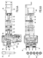
- FIG. 4 we now refer jointly to Figures 4 and 5 for describe the means of agitation 30.
- These include a support 86 which carries an electric motor 88, dr type not step, having a shaft 90 which extends along a horizontal axial direction X-X which is perpendicular to the direction of translation of the cassettes on the means of transfer 10, i.e. perpendicular to the path defined by the transfer means 10.
- the shaft 90 carries a screw 92 (threaded axis) cooperating with a nut 94 to constitute together a mechanism 96 of the type screw / nut ( Figures 4 and 5).
- Nut 94 is attached to a sleeve 95 guided in a flange 98 and is connected to a movable head 100 which carries the two gripping members 32.
- the electric motor 88 can be rotated, in one way or the other, under defined conditions, for selectively perform either the translational displacement of the movable head 100 in the direction of the axis X-X, that is to say its displacement in rotation around this axis.
- the stirring means 30 further comprise a stop 102 which consists of a lever 104 pivotally mounted around an axis 106 and actuated via a electromagnet 108.
- the lever 104 is able to cooperate with a disc 110 secured to the movable head 100 and provided with a notch 112.
- This stop member can be placed selectively either in a locking position in which the moving head 100 is immobilized in translation, either in a unlocking position, in which this movable head is integral with the nut in translation and in rotation.
- the motor 88 can be rotated in a direction V corresponding to the screwing, which allows the nut to be brought closer 94 (and therefore the moving head 100) of the motor 88, the moving head being immobilized in rotation by locking means.
- These the latter are composed of a bearing 132 and a groove 133 and will be described in detail later with reference to the figure 6. This movement thus allows the moving head to be moved away 100 of a cassette disposed on the transfer means.
- the motor 88 can also be driven in a corresponding direction D when unscrewing which removes nut 94 (and therefore the head mobile 100) of motor 88, this mobile head still being immobilized in rotation by the locking means 132 and 133.
- this movement allows the moving head to be brought closer 100 of the cassette disposed on the transfer means.
- each of the gripping members 32 comprises two bodies of clamp 114 each of which carries two jaws 116 and is mounted pivoting around an axis 118.
- Each gripper body defines a cam path 120 of selected shape which is intended for cooperate with a cam finger 121.
- the device comprises here four cam fingers 121 carried by axes 122 on a H-shaped support 124 mounted at the end 126 of a rod 128, itself mounted at the end of the sleeve 95.
- Rod 128 is slidable axially and in translation in an opening 129 of the disc 110, while its end 126 is able to slide in an opening 134 of the movable head.
- Rod 128 includes two flats 131, one of which comes to rest on a base 135 of the movable head 100, which allows to ensure or not a integral in rotation with the rod 128 and the head 100 according to their mutual axial position.
- the movable head 100 In the position of Figures 6A and 6B, the movable head 100 is in a position away from the cassette and therefore from the tubes of the latter.
- the coupling mechanism is near a stop position end of tightening.
- the aforementioned blocking means are composed of the bearing 132 which is integral with the sleeve 95 and which cooperates with the groove 133 of the support. These means realize a blockage in translation only or in rotation only.
- the moving head 100 approaches the cassette and therefore the tubes of the latter.
- the head abuts against a sheet before (not shown) which will then intervene during the replace the tube in the cassette.
- the head reaches thus in the position of FIGS. 7A and 7B, in which the jaws 116 of the gripping members are open for each time grab a tube from the cassette.
- the stop member 102 is actuated to place the lever 104 in the locking position as shown in dotted line (reference 104 '). This will block the head in the axial direction.
- the motor 88 is activated in the direction of screwing, which first causes the pivoting gripping organs and the approximation of their respective jaws to grasp a tube of the cassette.
- the locking means are brought back to the position of unlocking, as shown in FIGS. 8A and 8B, and continues the rotation of the motor 88 in the direction of screwing this which allows the moving head to be moved away from the cassette, the grippers holding a tube each time. During this movement, the moving head remains immobilized in rotation because the bearing 132 remains engaged in the throat 133.
- the means agitation extract two tubes each time from the cassette to shake them and then replace them in the cassette.
- the cassette is advanced, on the means of transfer, according to a chosen distance which is defined by the stepper motor 84 which activates the movement of the carriage 60.
- the tubes, previously agitated, are then brought, one to one, opposite the sampling means 34, which will be described later.
- the carriage mechanically actuates the ejection means 38.
- the carriage include a tilting member 136 (FIG. 1) mounted pivoting about an axis that extends parallel to the direction of the transfer means and which has a ramp 138 against which the carriage 60 cooperates for perform a pivoting movement of the tilting member.
- This the latter has two 140 pushers which support against the cassette to move it on the plate 36 in the direction of arrow F2. The cassettes are thus, after analysis, received in stack on the plate 36 of the means of unloading.
- the latter is disposed near the transfer means 10 and is suitable for receiving at least one tube 18, outside the presence of a cassette on the transfer means. he comprises a head 142 mounted to rotate and tilt and likely to be placed in different indexed positions. This head has housings 144 adapted for receive tubes of different dimensions.
- the head 142 can be placed in an inclined position, as shown in Figure 9, authorizing the loading of minus one tube in a suitable housing. Then this head is tilted to a vertical position, as shown on the Figure 10, in which the tube 18 is vertical for a operation to take a sample of blood product. As can be seen in Figures 9 and 10, the head can be rotated in different indexed positions in which the housing which carries the tube to be analyzed is located opposite the sampling means 34.
- Figure 11 we now refer to Figure 11 to describe the general structure of the sampling means. These latter include a carriage 146 movable in horizontal translation in a direction orthogonal to that of the means of transfer.
- This carriage 146 carries a piercer and a sampling needle associated (designated as a whole by the reference 148) and can be placed over a tube with a stopper is to be pierced.
- the piercer and the needle are then moved vertically from top to bottom to drill the tube cap and suction of a total amount sample.
- the sampling needle is connected to a suitable suction pump (not shown). Then the needle and the piercer are raised upwards and the carriage is moved so as to move away to come distribute fractions of the sample taken from different tanks 150 where a fraction of the sample is at each time mixed with a suitable reagent for analysis.
- sampling means can be carried out in accordance with the teachings of document EP-A-0 634 660.
- these means of withdrawal include advantageously cleaning means for cleaning the needle before and after each sampling operation.
- the stirring means provided for this purpose are less bulky and can be more easily integrated into the device of the invention.
- the device of the invention also offers the advantage that tubes can be loaded or unloaded in cassettes either laterally or vertically, in particular by the top.
- the invention finds particular application to analyzers hematological, such as those used in laboratories for analysis.
Applications Claiming Priority (2)
| Application Number | Priority Date | Filing Date | Title |
|---|---|---|---|
| FR0009623 | 2000-07-21 | ||
| FR0009623A FR2812088B1 (fr) | 2000-07-21 | 2000-07-21 | Dispositif de traitement d'echantillons de produits sanguins |
Publications (2)
| Publication Number | Publication Date |
|---|---|
| EP1174717A1 true EP1174717A1 (de) | 2002-01-23 |
| EP1174717B1 EP1174717B1 (de) | 2006-05-17 |
Family
ID=8852807
Family Applications (1)
| Application Number | Title | Priority Date | Filing Date |
|---|---|---|---|
| EP01401695A Expired - Lifetime EP1174717B1 (de) | 2000-07-21 | 2001-06-26 | Vorrichtung zur Behandlung von Blutproben |
Country Status (16)
| Country | Link |
|---|---|
| US (1) | US6818182B2 (de) |
| EP (1) | EP1174717B1 (de) |
| JP (1) | JP4683779B2 (de) |
| CN (1) | CN1207549C (de) |
| AT (1) | ATE326701T1 (de) |
| AU (1) | AU781892B2 (de) |
| BR (1) | BRPI0104022B8 (de) |
| CA (1) | CA2353318A1 (de) |
| DE (1) | DE60119629T2 (de) |
| DK (1) | DK1174717T3 (de) |
| ES (1) | ES2260178T3 (de) |
| FI (1) | FI20011544A (de) |
| FR (1) | FR2812088B1 (de) |
| HU (1) | HU223619B1 (de) |
| NO (1) | NO20013592L (de) |
| ZA (1) | ZA200105480B (de) |
Cited By (4)
| Publication number | Priority date | Publication date | Assignee | Title |
|---|---|---|---|---|
| FR2858057A1 (fr) * | 2003-07-21 | 2005-01-28 | Abx Sa | Dispositif de controle de qualite pour analyseur sanguin fonctionnant en sang total |
| FR2859285A1 (fr) * | 2003-08-26 | 2005-03-04 | Abx Sa | Analyseur hematologique sur sang total avec dispositif d'agitation |
| WO2014072616A1 (fr) * | 2012-11-09 | 2014-05-15 | Alain Rousseau-Techniques & Innovations (Arteion) | Dispositif d'analyse pour diagnostic in vitro |
| CN112353390A (zh) * | 2020-11-11 | 2021-02-12 | 贵州大学 | 一种针的自动装载、扎针与回收机构及控制方法 |
Families Citing this family (95)
| Publication number | Priority date | Publication date | Assignee | Title |
|---|---|---|---|---|
| US6048734A (en) | 1995-09-15 | 2000-04-11 | The Regents Of The University Of Michigan | Thermal microvalves in a fluid flow method |
| US6692700B2 (en) | 2001-02-14 | 2004-02-17 | Handylab, Inc. | Heat-reduction methods and systems related to microfluidic devices |
| US7010391B2 (en) | 2001-03-28 | 2006-03-07 | Handylab, Inc. | Methods and systems for control of microfluidic devices |
| US8895311B1 (en) | 2001-03-28 | 2014-11-25 | Handylab, Inc. | Methods and systems for control of general purpose microfluidic devices |
| US7829025B2 (en) | 2001-03-28 | 2010-11-09 | Venture Lending & Leasing Iv, Inc. | Systems and methods for thermal actuation of microfluidic devices |
| US7323140B2 (en) * | 2001-03-28 | 2008-01-29 | Handylab, Inc. | Moving microdroplets in a microfluidic device |
| US6852287B2 (en) | 2001-09-12 | 2005-02-08 | Handylab, Inc. | Microfluidic devices having a reduced number of input and output connections |
| US6790413B2 (en) * | 2001-05-03 | 2004-09-14 | Beckman Coulter, Inc. | Sample presentation unit |
| ATE479499T1 (de) * | 2001-07-20 | 2010-09-15 | Gen Probe Inc Patent Dept | Probenträger und tropfschirmvorrichtung und verfahren hierfür |
| JP4235171B2 (ja) | 2002-05-17 | 2009-03-11 | ジェン−プロウブ インコーポレイテッド | サンプルチューブブロッキング手段を備えるサンプルキャリアおよびそれと共に使用するためのドリップシールド |
| EP1507593B1 (de) | 2002-05-17 | 2007-10-17 | Gen-Probe Incorporated | Probenträger mit lösbarer sperreinrichtung |
| DE10247731B4 (de) * | 2002-10-12 | 2007-04-12 | Eppendorf Ag | Greifwerkzeug, Dosierwerkzeug und Werkzeughalter für einen Laborautomaten |
| AU2003287568A1 (en) * | 2002-11-08 | 2004-06-03 | Irm, Llc | Systems and methods of sorting samples |
| DE10322331B4 (de) * | 2003-05-17 | 2005-07-14 | Heidolph Instruments Gmbh & Co.Kg | Vorrichtung zum Durchführen einer Parallelsynthese von Verbindungen |
| JP4996248B2 (ja) | 2003-07-31 | 2012-08-08 | ハンディーラブ インコーポレイテッド | 粒子含有サンプルの処理 |
| US20050067308A1 (en) * | 2003-09-30 | 2005-03-31 | Thompson Brian J. | Trocar assembly tip protector |
| JP4355590B2 (ja) * | 2004-02-23 | 2009-11-04 | シスメックス株式会社 | 分析システム |
| US7850914B2 (en) * | 2004-03-05 | 2010-12-14 | Beckman Coulter, Inc. | Specimen-transport module for a multi-instrument clinical workcell |
| FR2867861B1 (fr) | 2004-03-16 | 2006-07-14 | Abx Sa | Dispositif pour l'approvisionnement d'analyseurs sur sang total |
| FR2867860B1 (fr) * | 2004-03-16 | 2006-07-14 | Abx Sa | Dispositif pour l'approvisionnement d'analyseurs sur sang en tubes de sang |
| JP3839441B2 (ja) * | 2004-03-22 | 2006-11-01 | 株式会社アイディエス | 試験管搬送路の搬送方向変換装置 |
| DE102004018598B4 (de) * | 2004-04-16 | 2006-04-27 | Bartec Gmbh | Anordnung und Verfahren zur automatischen Probenahme an Milchsammelwagen und Melkanlagen |
| WO2005108620A2 (en) * | 2004-05-03 | 2005-11-17 | Handylab, Inc. | Processing polynucleotide-containing samples |
| US8852862B2 (en) * | 2004-05-03 | 2014-10-07 | Handylab, Inc. | Method for processing polynucleotide-containing samples |
| US7910067B2 (en) | 2005-04-19 | 2011-03-22 | Gen-Probe Incorporated | Sample tube holder |
| FR2888328B1 (fr) * | 2005-07-08 | 2013-09-20 | Horiba Abx Sas | Procede automatise de preparation d'analyse d'echantillons de sang total et dispositif automatise pour sa mise en oeuvre |
| JP4781054B2 (ja) * | 2005-09-05 | 2011-09-28 | シスメックス株式会社 | 血液試料吸引装置を備える血液分析装置 |
| EP1945815A4 (de) * | 2005-10-11 | 2009-02-18 | Handylab Inc | Polynukleotidprobenvorbereitungsvorrichtung |
| EP1945172A2 (de) * | 2005-10-31 | 2008-07-23 | Medi-Physics, Inc. | Verfahren und system zur herstellung eines radiopharmazeutischen kits |
| JP4768410B2 (ja) * | 2005-11-15 | 2011-09-07 | シスメックス株式会社 | 撹拌装置及び試料分析装置 |
| JP4768409B2 (ja) | 2005-11-15 | 2011-09-07 | シスメックス株式会社 | 試料分析装置、試料分析本体装置、及び試料容器供給装置 |
| GB0601707D0 (en) * | 2006-01-27 | 2006-03-08 | Randox Lab Ltd | Assay Device Processing Apparatus And Method |
| US8883490B2 (en) | 2006-03-24 | 2014-11-11 | Handylab, Inc. | Fluorescence detector for microfluidic diagnostic system |
| US8088616B2 (en) | 2006-03-24 | 2012-01-03 | Handylab, Inc. | Heater unit for microfluidic diagnostic system |
| ES2692380T3 (es) | 2006-03-24 | 2018-12-03 | Handylab, Inc. | Método para realizar PCR con un cartucho con varias pistas |
| US10900066B2 (en) | 2006-03-24 | 2021-01-26 | Handylab, Inc. | Microfluidic system for amplifying and detecting polynucleotides in parallel |
| US11806718B2 (en) | 2006-03-24 | 2023-11-07 | Handylab, Inc. | Fluorescence detector for microfluidic diagnostic system |
| US7998708B2 (en) | 2006-03-24 | 2011-08-16 | Handylab, Inc. | Microfluidic system for amplifying and detecting polynucleotides in parallel |
| FR2907905B1 (fr) * | 2006-10-30 | 2009-04-03 | C2 Diagnostics Sa | "appareil et procede pour manipuler des tubes,notamment appareil automate d'analyse sanguine" |
| WO2008061165A2 (en) * | 2006-11-14 | 2008-05-22 | Handylab, Inc. | Microfluidic cartridge and method of making same |
| JP5128804B2 (ja) * | 2006-11-17 | 2013-01-23 | Ckd株式会社 | 検査方法及び検査装置 |
| US9186677B2 (en) | 2007-07-13 | 2015-11-17 | Handylab, Inc. | Integrated apparatus for performing nucleic acid extraction and diagnostic testing on multiple biological samples |
| USD621060S1 (en) | 2008-07-14 | 2010-08-03 | Handylab, Inc. | Microfluidic cartridge |
| US8105783B2 (en) | 2007-07-13 | 2012-01-31 | Handylab, Inc. | Microfluidic cartridge |
| AU2008276211B2 (en) * | 2007-07-13 | 2015-01-22 | Handylab, Inc. | Polynucleotide capture materials, and methods of using same |
| US20090136385A1 (en) * | 2007-07-13 | 2009-05-28 | Handylab, Inc. | Reagent Tube |
| US8133671B2 (en) | 2007-07-13 | 2012-03-13 | Handylab, Inc. | Integrated apparatus for performing nucleic acid extraction and diagnostic testing on multiple biological samples |
| US9618139B2 (en) | 2007-07-13 | 2017-04-11 | Handylab, Inc. | Integrated heater and magnetic separator |
| US8182763B2 (en) | 2007-07-13 | 2012-05-22 | Handylab, Inc. | Rack for sample tubes and reagent holders |
| US8287820B2 (en) | 2007-07-13 | 2012-10-16 | Handylab, Inc. | Automated pipetting apparatus having a combined liquid pump and pipette head system |
| US7678331B2 (en) * | 2007-12-20 | 2010-03-16 | Abbott Laboratories Inc. | Automatic loading of sample tubes for clinical analyzer |
| FR2927173B1 (fr) * | 2008-02-05 | 2010-03-05 | Stago Diagnostica | Alimentation d'un appareil automatique d'analyse en cuvettes de reaction |
| JP5198095B2 (ja) * | 2008-03-07 | 2013-05-15 | シスメックス株式会社 | 分析装置および分析方法 |
| JP5280882B2 (ja) * | 2008-06-30 | 2013-09-04 | シスメックス株式会社 | 分析装置 |
| US20100009351A1 (en) * | 2008-07-11 | 2010-01-14 | Handylab, Inc. | Polynucleotide Capture Materials, and Method of Using Same |
| USD618820S1 (en) | 2008-07-11 | 2010-06-29 | Handylab, Inc. | Reagent holder |
| USD787087S1 (en) | 2008-07-14 | 2017-05-16 | Handylab, Inc. | Housing |
| JP5373560B2 (ja) * | 2008-11-17 | 2013-12-18 | シスメックス株式会社 | 搬送装置及びこれを用いた検体分析装置 |
| BR112013001647A2 (pt) * | 2010-07-23 | 2016-05-24 | Beckman Coulter Inc | sistema e método contendo unidades analíticas |
| US9144801B2 (en) | 2010-08-31 | 2015-09-29 | Abbott Laboratories | Sample tube racks having retention bars |
| CN102043063B (zh) * | 2010-12-30 | 2012-10-31 | 长春迪瑞医疗科技股份有限公司 | 连接桥 |
| ES2769028T3 (es) | 2011-04-15 | 2020-06-24 | Becton Dickinson Co | Termociclador microfluídico de barrido en tiempo real |
| KR20140036178A (ko) | 2011-05-13 | 2014-03-25 | 베크만 컬터, 인코포레이티드 | 실험실 제품 이송 요소 및 경로 배열 구조체 |
| US9248982B2 (en) | 2011-05-13 | 2016-02-02 | Beckman Coulter, Inc. | System and method including laboratory product transport element |
| WO2013016035A1 (en) | 2011-07-22 | 2013-01-31 | Constitution Medical, Inc. | Sample transport systems and methods |
| CA2842680A1 (en) | 2011-07-22 | 2013-01-31 | Roche Diagnostics Hematology, Inc. | Fluid sample preparation systems and methods |
| USD692162S1 (en) | 2011-09-30 | 2013-10-22 | Becton, Dickinson And Company | Single piece reagent holder |
| DK3273253T3 (da) | 2011-09-30 | 2020-10-12 | Becton Dickinson Co | Forenet reagensstrimmel |
| CN104040238B (zh) | 2011-11-04 | 2017-06-27 | 汉迪拉布公司 | 多核苷酸样品制备装置 |
| JP5808653B2 (ja) | 2011-11-18 | 2015-11-10 | シスメックス株式会社 | 血球計数装置および血球計数方法 |
| CN107881219B (zh) | 2012-02-03 | 2021-09-10 | 贝克顿·迪金森公司 | 用于分子诊断测试分配和测试之间兼容性确定的外部文件 |
| CN103364577B (zh) * | 2012-03-29 | 2014-11-26 | 深圳市开立科技有限公司 | 用于血细胞分析仪的进样取样装置 |
| WO2014048473A1 (en) | 2012-09-27 | 2014-04-03 | Pz Cormay S.A. | Method and device for delivering fluid sample to analyzing apparatus |
| FR3040892B1 (fr) * | 2015-09-14 | 2019-05-31 | Olivier Charansonney | Dispositif de melange et d'homogeneisation d'un milieu complexe |
| FR3047082B1 (fr) | 2016-01-25 | 2018-02-16 | Arteion | Systeme de convoyage de supports pour recipients d’echantillons de liquide biologique, et systeme d’analyse automatique comprenant un tel systeme de convoyage |
| RU173046U1 (ru) * | 2016-04-18 | 2017-08-08 | Общество с ограниченной ответственностью "Компания Алкор Био" (ООО "Компания Алкор Био") | Прибор для автоматического анализа крови |
| CN106018766A (zh) * | 2016-05-09 | 2016-10-12 | 中山市创艺生化工程有限公司 | 一种用于血细胞分析仪的抓手机构 |
| NL2017163B1 (en) * | 2016-07-14 | 2018-01-18 | R&R Mechatronics Int B V | Sample tube holder |
| FR3054560B1 (fr) * | 2016-07-28 | 2018-08-17 | Horiba Abx Sas | Dispositif d'agitation et de prelevement d'echantillons de liquides biologiques |
| CN106198944A (zh) * | 2016-08-31 | 2016-12-07 | 郭鑫 | 一种专业用急诊内科用血分析仪 |
| CN109521210A (zh) * | 2017-09-19 | 2019-03-26 | 江苏雷镈智能科技有限公司 | 全自动试管装载设备及其方法 |
| CN109682981A (zh) * | 2017-10-19 | 2019-04-26 | 深圳迈瑞生物医疗电子股份有限公司 | 样本移送设备、样本分析系统及其控制方法 |
| CN107826672A (zh) * | 2017-11-23 | 2018-03-23 | 昌微系统科技(上海)有限公司 | 一种试管架的传送控制装置 |
| JP6991335B2 (ja) * | 2017-12-05 | 2022-01-12 | シーメンス・ヘルスケア・ダイアグノスティックス・インコーポレイテッド | 自動診断分析装置のためのプローブ先端廃棄物シュートおよびその方法 |
| CN108043295A (zh) * | 2017-12-07 | 2018-05-18 | 张荷友 | 一种液体食品检测用摇匀装置 |
| USD892351S1 (en) * | 2018-03-06 | 2020-08-04 | Ventana Medical Systems, Inc. | Biological slide tray |
| CN112654850A (zh) * | 2018-08-24 | 2021-04-13 | 深圳迈瑞生物医疗电子股份有限公司 | 血样分析仪及血样混匀方法 |
| CN110628570A (zh) * | 2019-10-18 | 2019-12-31 | 中信湘雅生殖与遗传专科医院有限公司 | 转移抓手 |
| CN113551945A (zh) * | 2020-04-24 | 2021-10-26 | 南京劳拉苏埃尔电子有限公司 | 一种自动感应液面的真空采血管自动穿刺装置 |
| CN112316811B (zh) * | 2020-10-30 | 2022-06-21 | 孙继爽 | 一种中药药材检测用振摇器 |
| CN112808119B (zh) * | 2021-01-19 | 2022-06-24 | 西安交通大学医学院第一附属医院 | 一种血液内科骨髓采集后快速摇匀装置 |
| CN112916078A (zh) * | 2021-01-21 | 2021-06-08 | 施宝益 | 一种用于医疗科室的智能医疗检测装置 |
| CN113109262A (zh) * | 2021-04-20 | 2021-07-13 | 蓝莲(杭州)生物科技有限公司 | 一种实验室用细胞分析仪 |
| CN113042131B (zh) * | 2021-04-21 | 2022-07-19 | 刘朗宁 | 一种微生物实验用试管架 |
| CN113856786B (zh) * | 2021-10-29 | 2022-10-11 | 江苏睿玻生物科技有限公司 | 枪头的自动运输组件、自动运输方法以及移液系统 |
Citations (8)
| Publication number | Priority date | Publication date | Assignee | Title |
|---|---|---|---|---|
| FR1562948A (de) * | 1968-01-23 | 1969-04-11 | ||
| JPS5763122A (en) * | 1980-10-01 | 1982-04-16 | Fujirebio Inc | Stirrer |
| EP0275119A2 (de) * | 1987-01-16 | 1988-07-20 | Mitsubishi Kasei Corporation | Automatisches Probenhandhabungsgerät |
| US4921676A (en) * | 1987-01-29 | 1990-05-01 | Toa Medical Electronics Co., Ltd. | Shaking apparatus for agitating and withdrawing a specimen in a sealed vessel |
| FR2692358A1 (fr) * | 1992-06-11 | 1993-12-17 | Abx Sa | Dispositif de transfert, d'agitation et de prélèvement d'échantillons de produits sanguins en tubes regroupés dans des cassettes, notamment pour analyseurs hématologiques. |
| EP0634660A1 (de) * | 1993-07-15 | 1995-01-18 | ABX , Société Anonyme dite | Reinigungsvorrichtung für eine Kanüle zur Entnahme eine Flüssigkeitsprobe aus einer geschlossenen Flasche |
| DE19504748A1 (de) * | 1994-08-16 | 1996-04-11 | Rathor Ag | Mischvorrichtung für geschlossene Behälter mit einem aus mehreren schwer mischbaren, vorzugsweise flüssigen Substraten |
| FR2730315A1 (fr) * | 1995-02-07 | 1996-08-09 | Abx Sa | Dispositif d'agitation et de prelevement d'echantillons de produits sanguins dans des tubes regroupes dans des cassettes |
Family Cites Families (18)
| Publication number | Priority date | Publication date | Assignee | Title |
|---|---|---|---|---|
| US3644095A (en) * | 1967-12-20 | 1972-02-22 | Eppendorf Geractebau Netheler | Apparatus for performing chemical analyses |
| US4039286A (en) * | 1976-07-16 | 1977-08-02 | W. C. Heraeus Gmbh | Automatic chemical analysis apparatus |
| US4609017A (en) * | 1983-10-13 | 1986-09-02 | Coulter Electronics, Inc. | Method and apparatus for transporting carriers of sealed sample tubes and mixing the samples |
| US4861553A (en) * | 1987-06-11 | 1989-08-29 | Technicon Instruments Corporation | Automatic sampling system |
| DE4023165A1 (de) * | 1990-07-20 | 1992-01-23 | Kodak Ag | Vorrichtung zum abtasten und zentrieren von behaeltern mit einer fluessigkeit |
| US6498037B1 (en) * | 1991-03-04 | 2002-12-24 | Bayer Corporation | Method of handling reagents in a random access protocol |
| JPH0671585A (ja) * | 1992-08-25 | 1994-03-15 | Matsushita Electric Ind Co Ltd | 上下回転装置 |
| ATE266206T1 (de) * | 1993-09-17 | 2004-05-15 | Hoffmann La Roche | Analysengerät mit einer vorrichtung zur suspension von partikeln und ein verfahren zur durchführung der suspension |
| CA2192652A1 (en) * | 1994-07-11 | 1996-01-25 | Prabhakar P. Rao | Modular vial autosampler |
| US5948360A (en) * | 1994-07-11 | 1999-09-07 | Tekmar Company | Autosampler with robot arm |
| US6066300A (en) * | 1995-07-07 | 2000-05-23 | Bayer Corporation | Reagent handling system and configurable vial carrier for use therein |
| WO1997005492A1 (fr) * | 1995-07-31 | 1997-02-13 | Precision System Science Co., Ltd | Recipient |
| JP3704570B2 (ja) * | 1996-08-28 | 2005-10-12 | アークレイ株式会社 | チャッキング装置、およびこれを備えた試料検査装置 |
| US6045755A (en) * | 1997-03-10 | 2000-04-04 | Trega Biosciences,, Inc. | Apparatus and method for combinatorial chemistry synthesis |
| US5861563A (en) * | 1997-03-20 | 1999-01-19 | Bayer Corporation | Automatic closed tube sampler |
| US6913934B2 (en) * | 1998-08-13 | 2005-07-05 | Symyx Technologies, Inc. | Apparatus and methods for parallel processing of multiple reaction mixtures |
| US6413780B1 (en) * | 1998-10-14 | 2002-07-02 | Abbott Laboratories | Structure and method for performing a determination of an item of interest in a sample |
| DE59906386D1 (de) * | 1998-11-03 | 2003-08-28 | Hettlab Ag Baech | Vakuumzentrifuge bzw. Reaktionskammer |
-
2000
- 2000-07-21 FR FR0009623A patent/FR2812088B1/fr not_active Expired - Fee Related
-
2001
- 2001-06-26 DE DE60119629T patent/DE60119629T2/de not_active Expired - Lifetime
- 2001-06-26 ES ES01401695T patent/ES2260178T3/es not_active Expired - Lifetime
- 2001-06-26 AT AT01401695T patent/ATE326701T1/de not_active IP Right Cessation
- 2001-06-26 DK DK01401695T patent/DK1174717T3/da active
- 2001-06-26 EP EP01401695A patent/EP1174717B1/de not_active Expired - Lifetime
- 2001-06-26 AU AU54058/01A patent/AU781892B2/en not_active Ceased
- 2001-06-29 HU HU0102720A patent/HU223619B1/hu not_active IP Right Cessation
- 2001-07-03 ZA ZA200105480A patent/ZA200105480B/xx unknown
- 2001-07-13 FI FI20011544A patent/FI20011544A/fi not_active IP Right Cessation
- 2001-07-18 BR BRPI0104022A patent/BRPI0104022B8/pt not_active IP Right Cessation
- 2001-07-19 CA CA002353318A patent/CA2353318A1/fr not_active Abandoned
- 2001-07-19 JP JP2001220087A patent/JP4683779B2/ja not_active Expired - Lifetime
- 2001-07-20 NO NO20013592A patent/NO20013592L/no not_active Application Discontinuation
- 2001-07-20 CN CNB011232196A patent/CN1207549C/zh not_active Expired - Lifetime
- 2001-07-23 US US09/909,996 patent/US6818182B2/en not_active Expired - Lifetime
Patent Citations (9)
| Publication number | Priority date | Publication date | Assignee | Title |
|---|---|---|---|---|
| FR1562948A (de) * | 1968-01-23 | 1969-04-11 | ||
| JPS5763122A (en) * | 1980-10-01 | 1982-04-16 | Fujirebio Inc | Stirrer |
| EP0275119A2 (de) * | 1987-01-16 | 1988-07-20 | Mitsubishi Kasei Corporation | Automatisches Probenhandhabungsgerät |
| US4921676A (en) * | 1987-01-29 | 1990-05-01 | Toa Medical Electronics Co., Ltd. | Shaking apparatus for agitating and withdrawing a specimen in a sealed vessel |
| FR2692358A1 (fr) * | 1992-06-11 | 1993-12-17 | Abx Sa | Dispositif de transfert, d'agitation et de prélèvement d'échantillons de produits sanguins en tubes regroupés dans des cassettes, notamment pour analyseurs hématologiques. |
| EP0634660A1 (de) * | 1993-07-15 | 1995-01-18 | ABX , Société Anonyme dite | Reinigungsvorrichtung für eine Kanüle zur Entnahme eine Flüssigkeitsprobe aus einer geschlossenen Flasche |
| DE19504748A1 (de) * | 1994-08-16 | 1996-04-11 | Rathor Ag | Mischvorrichtung für geschlossene Behälter mit einem aus mehreren schwer mischbaren, vorzugsweise flüssigen Substraten |
| FR2730315A1 (fr) * | 1995-02-07 | 1996-08-09 | Abx Sa | Dispositif d'agitation et de prelevement d'echantillons de produits sanguins dans des tubes regroupes dans des cassettes |
| US5665309A (en) * | 1995-02-07 | 1997-09-09 | Abx | Device for agitating and for taking samples of blood products from tubes which are grouped together in racks |
Non-Patent Citations (1)
| Title |
|---|
| PATENT ABSTRACTS OF JAPAN vol. 006, no. 139 (C - 116) 28 July 1982 (1982-07-28) * |
Cited By (15)
| Publication number | Priority date | Publication date | Assignee | Title |
|---|---|---|---|---|
| AU2004267523B2 (en) * | 2003-07-21 | 2010-01-28 | Horiba Abx S.A. | Quality control device for a blood analyser using whole blood |
| WO2005019835A1 (fr) * | 2003-07-21 | 2005-03-03 | Horiba Abx Sa. | Dispositif de controle de qualite pour un analyseur sanguin fonctionnant en sang total |
| CN1826530B (zh) * | 2003-07-21 | 2011-12-14 | 奥里巴Abx股份有限公司 | 用于分析全血的血液分析仪的质量控制设备 |
| FR2858057A1 (fr) * | 2003-07-21 | 2005-01-28 | Abx Sa | Dispositif de controle de qualite pour analyseur sanguin fonctionnant en sang total |
| US8029732B2 (en) | 2003-07-21 | 2011-10-04 | Horiba Abx Sa | Quality control device for a blood analyser using whole blood |
| WO2005022168A2 (fr) * | 2003-08-26 | 2005-03-10 | Horiba Abx Sas | Analyseur hématologique sur sang total avec dispositif d'agitation |
| WO2005022168A3 (fr) * | 2003-08-26 | 2005-05-12 | Abx Sa | Analyseur hématologique sur sang total avec dispositif d'agitation |
| FR2859285A1 (fr) * | 2003-08-26 | 2005-03-04 | Abx Sa | Analyseur hematologique sur sang total avec dispositif d'agitation |
| US8852505B2 (en) | 2003-08-26 | 2014-10-07 | Horiba Abx Sas | Hematological analyzer on whole blood with stirring device |
| WO2014072616A1 (fr) * | 2012-11-09 | 2014-05-15 | Alain Rousseau-Techniques & Innovations (Arteion) | Dispositif d'analyse pour diagnostic in vitro |
| FR2998057A1 (fr) * | 2012-11-09 | 2014-05-16 | Alain Rousseau Tech & Innovations Arteion | Dispositif d’analyse pour diagnostic in vitro |
| RU2645771C2 (ru) * | 2012-11-09 | 2018-02-28 | Артеион | Устройство выполнения анализов для диагностики in vitro |
| US9989546B2 (en) | 2012-11-09 | 2018-06-05 | Arteion | Analysis device for in vitro diagnostics |
| CN112353390A (zh) * | 2020-11-11 | 2021-02-12 | 贵州大学 | 一种针的自动装载、扎针与回收机构及控制方法 |
| CN112353390B (zh) * | 2020-11-11 | 2023-05-26 | 贵州大学 | 一种针的自动装载、扎针与回收机构及控制方法 |
Also Published As
| Publication number | Publication date |
|---|---|
| FI20011544A0 (fi) | 2001-07-13 |
| FR2812088B1 (fr) | 2003-01-24 |
| AU5405801A (en) | 2002-01-24 |
| CN1207549C (zh) | 2005-06-22 |
| AU781892B2 (en) | 2005-06-23 |
| BRPI0104022B8 (pt) | 2021-07-27 |
| US20020021983A1 (en) | 2002-02-21 |
| ZA200105480B (en) | 2002-01-17 |
| DE60119629D1 (de) | 2006-06-22 |
| JP4683779B2 (ja) | 2011-05-18 |
| FR2812088A1 (fr) | 2002-01-25 |
| ES2260178T3 (es) | 2006-11-01 |
| HU0102720D0 (en) | 2001-08-28 |
| DE60119629T2 (de) | 2007-04-26 |
| BR0104022B1 (pt) | 2013-04-02 |
| HU223619B1 (hu) | 2004-10-28 |
| EP1174717B1 (de) | 2006-05-17 |
| NO20013592L (no) | 2002-01-22 |
| ATE326701T1 (de) | 2006-06-15 |
| CN1334453A (zh) | 2002-02-06 |
| BR0104022A (pt) | 2002-02-26 |
| CA2353318A1 (fr) | 2002-01-21 |
| NO20013592D0 (no) | 2001-07-20 |
| US6818182B2 (en) | 2004-11-16 |
| JP2002071699A (ja) | 2002-03-12 |
| DK1174717T3 (da) | 2006-06-26 |
| FI20011544A (fi) | 2002-01-22 |
| HUP0102720A2 (hu) | 2002-04-29 |
Similar Documents
| Publication | Publication Date | Title |
|---|---|---|
| EP1174717B1 (de) | Vorrichtung zur Behandlung von Blutproben | |
| EP0726453B1 (de) | Vorrichtung zum Rühren und Entnehmen von Blutprodukten aus Proberöhrchen die in einen Gestell angeordnet sind | |
| EP1303761B1 (de) | Vorrichtung zur analyse von proben | |
| EP0645006B1 (de) | Vorrichtung zum transferieren, ruehren und entnehmen von blutprodukten aus proberoehrchen, die in einen gestell angeordnet sind | |
| EP1660857B1 (de) | Probenahmevorrichtung und verfahren für einen analyseautomaten | |
| CH650594A5 (fr) | Dispositif d'alimentation en echantillon pour appareil d'analyse. | |
| EP2092347B1 (de) | Vorrichtung und verfahren zur handhabung von röhrchen, insbesondere automatische blutanalysevorrichtung | |
| WO2005101024A1 (fr) | Dispositif pour l'approvisionnement d'analyseurs sur sang total en tubes de sang | |
| FR2508184A1 (fr) | Organe de maintien porte-lamelle et installation automatisee d'analyse par microscope | |
| FR2932273A1 (fr) | Pince adaptee pour saisir un support d'echantillons biologiques, ensemble d'un support echantillons biologiques et d'une pince adaptee pour le saisir, et automate de traitement et/ou d'analyse d'echantillons biologiques | |
| EP3491394B1 (de) | Vorrichtung zum schütteln und entnehmen von biologischen flüssigkeiten | |
| WO2014072616A1 (fr) | Dispositif d'analyse pour diagnostic in vitro | |
| EP0922229B1 (de) | Verfahren zur kontinuierlichen oder diskontinuierlichen automatischen analyse von in behältern plazierten proben | |
| FR2569479A1 (fr) | Appareil de traitement d'echantillons, notamment d'echantillons de tissus | |
| FR2804510A1 (fr) | Cuvettes, appareil d'analyse biologique automatise utilisant de telles cuvettes, moyen de transfert de cuvettes dans un tel appareil et procede de transfert | |
| FR2609808A1 (fr) | Appareil pour la distribution de milieux dans des receptacles groupes sur des plaques | |
| EP0369840A1 (de) | Probenträger mit Einstellungsmitteln für einen atomatischen Probenanalysator mittels Kolorimetrie | |
| WO2004109296A1 (fr) | Procede et dispositif de mise en place d’un recipient dans un dispositif de prelevement de liquide | |
| CH509921A (fr) | Installation de transport et de manipulation d'échantillons de matière | |
| FR3107045A1 (fr) | Systeme d’analyse en particulier pour des prelevements laitiers | |
| EP3903108A1 (de) | Probentransporteinheit für eine diagnosemaschine | |
| FR2726652A1 (fr) | Appareil automatique de dosage immunologique | |
| FR2505779A1 (fr) | Machine pour le remplissage et l'obturation en milieu radioactif de colonnes ouvertes a leurs deux extremites | |
| EP0533560A1 (de) | Orientierungs- und Behandlungsvorrichtung für längliche Werkstücke mit einem dünnen Ende |
Legal Events
| Date | Code | Title | Description |
|---|---|---|---|
| PUAI | Public reference made under article 153(3) epc to a published international application that has entered the european phase |
Free format text: ORIGINAL CODE: 0009012 |
|
| AK | Designated contracting states |
Kind code of ref document: A1 Designated state(s): AT BE CH CY DE DK ES FI FR GB GR IE IT LI LU MC NL PT SE TR |
|
| AX | Request for extension of the european patent |
Free format text: AL;LT;LV;MK;RO;SI |
|
| 17P | Request for examination filed |
Effective date: 20020107 |
|
| AKX | Designation fees paid |
Free format text: AT BE CH CY DE DK ES FI FR GB GR IE IT LI LU MC NL PT SE TR |
|
| 17Q | First examination report despatched |
Effective date: 20040813 |
|
| GRAP | Despatch of communication of intention to grant a patent |
Free format text: ORIGINAL CODE: EPIDOSNIGR1 |
|
| GRAS | Grant fee paid |
Free format text: ORIGINAL CODE: EPIDOSNIGR3 |
|
| GRAA | (expected) grant |
Free format text: ORIGINAL CODE: 0009210 |
|
| RAP1 | Party data changed (applicant data changed or rights of an application transferred) |
Owner name: HORIBA ABX S.A. |
|
| AK | Designated contracting states |
Kind code of ref document: B1 Designated state(s): AT BE CH CY DE DK ES FI FR GB GR IE IT LI LU MC NL PT SE TR |
|
| PG25 | Lapsed in a contracting state [announced via postgrant information from national office to epo] |
Ref country code: FI Free format text: LAPSE BECAUSE OF FAILURE TO SUBMIT A TRANSLATION OF THE DESCRIPTION OR TO PAY THE FEE WITHIN THE PRESCRIBED TIME-LIMIT Effective date: 20060517 Ref country code: IE Free format text: LAPSE BECAUSE OF FAILURE TO SUBMIT A TRANSLATION OF THE DESCRIPTION OR TO PAY THE FEE WITHIN THE PRESCRIBED TIME-LIMIT Effective date: 20060517 |
|
| REG | Reference to a national code |
Ref country code: GB Ref legal event code: FG4D Free format text: NOT ENGLISH |
|
| REG | Reference to a national code |
Ref country code: CH Ref legal event code: EP |
|
| REG | Reference to a national code |
Ref country code: IE Ref legal event code: FG4D Free format text: LANGUAGE OF EP DOCUMENT: FRENCH |
|
| REF | Corresponds to: |
Ref document number: 60119629 Country of ref document: DE Date of ref document: 20060622 Kind code of ref document: P |
|
| REG | Reference to a national code |
Ref country code: DK Ref legal event code: T3 |
|
| PG25 | Lapsed in a contracting state [announced via postgrant information from national office to epo] |
Ref country code: MC Free format text: LAPSE BECAUSE OF NON-PAYMENT OF DUE FEES Effective date: 20060630 |
|
| REG | Reference to a national code |
Ref country code: GR Ref legal event code: EP Ref document number: 20060401820 Country of ref document: GR Ref country code: CH Ref legal event code: NV Representative=s name: KATZAROV S.A. |
|
| GBT | Gb: translation of ep patent filed (gb section 77(6)(a)/1977) |
Effective date: 20060727 |
|
| REG | Reference to a national code |
Ref country code: SE Ref legal event code: TRGR |
|
| PG25 | Lapsed in a contracting state [announced via postgrant information from national office to epo] |
Ref country code: PT Free format text: LAPSE BECAUSE OF FAILURE TO SUBMIT A TRANSLATION OF THE DESCRIPTION OR TO PAY THE FEE WITHIN THE PRESCRIBED TIME-LIMIT Effective date: 20061017 |
|
| REG | Reference to a national code |
Ref country code: ES Ref legal event code: FG2A Ref document number: 2260178 Country of ref document: ES Kind code of ref document: T3 |
|
| REG | Reference to a national code |
Ref country code: IE Ref legal event code: FD4D |
|
| PLBE | No opposition filed within time limit |
Free format text: ORIGINAL CODE: 0009261 |
|
| STAA | Information on the status of an ep patent application or granted ep patent |
Free format text: STATUS: NO OPPOSITION FILED WITHIN TIME LIMIT |
|
| 26N | No opposition filed |
Effective date: 20070220 |
|
| PGFP | Annual fee paid to national office [announced via postgrant information from national office to epo] |
Ref country code: AT Payment date: 20070618 Year of fee payment: 7 |
|
| PGFP | Annual fee paid to national office [announced via postgrant information from national office to epo] |
Ref country code: BE Payment date: 20070627 Year of fee payment: 7 |
|
| PGFP | Annual fee paid to national office [announced via postgrant information from national office to epo] |
Ref country code: DK Payment date: 20070628 Year of fee payment: 7 |
|
| PG25 | Lapsed in a contracting state [announced via postgrant information from national office to epo] |
Ref country code: LU Free format text: LAPSE BECAUSE OF NON-PAYMENT OF DUE FEES Effective date: 20060626 |
|
| PGFP | Annual fee paid to national office [announced via postgrant information from national office to epo] |
Ref country code: TR Payment date: 20080529 Year of fee payment: 8 |
|
| PGFP | Annual fee paid to national office [announced via postgrant information from national office to epo] |
Ref country code: CH Payment date: 20080918 Year of fee payment: 8 Ref country code: NL Payment date: 20080618 Year of fee payment: 8 Ref country code: SE Payment date: 20080611 Year of fee payment: 8 |
|
| PG25 | Lapsed in a contracting state [announced via postgrant information from national office to epo] |
Ref country code: CY Free format text: LAPSE BECAUSE OF FAILURE TO SUBMIT A TRANSLATION OF THE DESCRIPTION OR TO PAY THE FEE WITHIN THE PRESCRIBED TIME-LIMIT Effective date: 20060517 |
|
| BERE | Be: lapsed |
Owner name: S.A. *0ORIBA ABX Effective date: 20080630 |
|
| REG | Reference to a national code |
Ref country code: DK Ref legal event code: EBP |
|
| PG25 | Lapsed in a contracting state [announced via postgrant information from national office to epo] |
Ref country code: BE Free format text: LAPSE BECAUSE OF NON-PAYMENT OF DUE FEES Effective date: 20080630 |
|
| PG25 | Lapsed in a contracting state [announced via postgrant information from national office to epo] |
Ref country code: AT Free format text: LAPSE BECAUSE OF NON-PAYMENT OF DUE FEES Effective date: 20080626 |
|
| PGFP | Annual fee paid to national office [announced via postgrant information from national office to epo] |
Ref country code: GR Payment date: 20080624 Year of fee payment: 8 |
|
| PG25 | Lapsed in a contracting state [announced via postgrant information from national office to epo] |
Ref country code: DK Free format text: LAPSE BECAUSE OF NON-PAYMENT OF DUE FEES Effective date: 20090106 |
|
| REG | Reference to a national code |
Ref country code: CH Ref legal event code: PL |
|
| NLV4 | Nl: lapsed or anulled due to non-payment of the annual fee |
Effective date: 20100101 |
|
| PG25 | Lapsed in a contracting state [announced via postgrant information from national office to epo] |
Ref country code: CH Free format text: LAPSE BECAUSE OF NON-PAYMENT OF DUE FEES Effective date: 20090630 Ref country code: LI Free format text: LAPSE BECAUSE OF NON-PAYMENT OF DUE FEES Effective date: 20090630 |
|
| PG25 | Lapsed in a contracting state [announced via postgrant information from national office to epo] |
Ref country code: DK Free format text: LAPSE BECAUSE OF NON-PAYMENT OF DUE FEES Effective date: 20080630 |
|
| PG25 | Lapsed in a contracting state [announced via postgrant information from national office to epo] |
Ref country code: NL Free format text: LAPSE BECAUSE OF NON-PAYMENT OF DUE FEES Effective date: 20100101 |
|
| PG25 | Lapsed in a contracting state [announced via postgrant information from national office to epo] |
Ref country code: GR Free format text: LAPSE BECAUSE OF NON-PAYMENT OF DUE FEES Effective date: 20100107 |
|
| PG25 | Lapsed in a contracting state [announced via postgrant information from national office to epo] |
Ref country code: SE Free format text: LAPSE BECAUSE OF NON-PAYMENT OF DUE FEES Effective date: 20090627 |
|
| PG25 | Lapsed in a contracting state [announced via postgrant information from national office to epo] |
Ref country code: TR Free format text: LAPSE BECAUSE OF NON-PAYMENT OF DUE FEES Effective date: 20090626 |
|
| REG | Reference to a national code |
Ref country code: FR Ref legal event code: PLFP Year of fee payment: 16 |
|
| REG | Reference to a national code |
Ref country code: FR Ref legal event code: PLFP Year of fee payment: 17 |
|
| REG | Reference to a national code |
Ref country code: FR Ref legal event code: PLFP Year of fee payment: 18 |
|
| PGFP | Annual fee paid to national office [announced via postgrant information from national office to epo] |
Ref country code: DE Payment date: 20200623 Year of fee payment: 20 Ref country code: FR Payment date: 20200623 Year of fee payment: 20 |
|
| PGFP | Annual fee paid to national office [announced via postgrant information from national office to epo] |
Ref country code: GB Payment date: 20200625 Year of fee payment: 20 |
|
| PGFP | Annual fee paid to national office [announced via postgrant information from national office to epo] |
Ref country code: ES Payment date: 20200717 Year of fee payment: 20 |
|
| PGFP | Annual fee paid to national office [announced via postgrant information from national office to epo] |
Ref country code: IT Payment date: 20200630 Year of fee payment: 20 |
|
| REG | Reference to a national code |
Ref country code: DE Ref legal event code: R071 Ref document number: 60119629 Country of ref document: DE |
|
| REG | Reference to a national code |
Ref country code: GB Ref legal event code: PE20 Expiry date: 20210625 |
|
| PG25 | Lapsed in a contracting state [announced via postgrant information from national office to epo] |
Ref country code: GB Free format text: LAPSE BECAUSE OF EXPIRATION OF PROTECTION Effective date: 20210625 |
|
| REG | Reference to a national code |
Ref country code: ES Ref legal event code: FD2A Effective date: 20211013 |
|
| PG25 | Lapsed in a contracting state [announced via postgrant information from national office to epo] |
Ref country code: ES Free format text: LAPSE BECAUSE OF EXPIRATION OF PROTECTION Effective date: 20210627 |