EP1174717A1 - Device for handling blood samples - Google Patents
Device for handling blood samples Download PDFInfo
- Publication number
- EP1174717A1 EP1174717A1 EP01401695A EP01401695A EP1174717A1 EP 1174717 A1 EP1174717 A1 EP 1174717A1 EP 01401695 A EP01401695 A EP 01401695A EP 01401695 A EP01401695 A EP 01401695A EP 1174717 A1 EP1174717 A1 EP 1174717A1
- Authority
- EP
- European Patent Office
- Prior art keywords
- cassette
- tube
- tubes
- sampling
- sample
- Prior art date
- Legal status (The legal status is an assumption and is not a legal conclusion. Google has not performed a legal analysis and makes no representation as to the accuracy of the status listed.)
- Granted
Links
Images


Classifications
-
- G—PHYSICS
- G01—MEASURING; TESTING
- G01N—INVESTIGATING OR ANALYSING MATERIALS BY DETERMINING THEIR CHEMICAL OR PHYSICAL PROPERTIES
- G01N35/00—Automatic analysis not limited to methods or materials provided for in any single one of groups G01N1/00 - G01N33/00; Handling materials therefor
- G01N35/10—Devices for transferring samples or any liquids to, in, or from, the analysis apparatus, e.g. suction devices, injection devices
- G01N35/1079—Devices for transferring samples or any liquids to, in, or from, the analysis apparatus, e.g. suction devices, injection devices with means for piercing stoppers or septums
-
- B—PERFORMING OPERATIONS; TRANSPORTING
- B01—PHYSICAL OR CHEMICAL PROCESSES OR APPARATUS IN GENERAL
- B01F—MIXING, e.g. DISSOLVING, EMULSIFYING OR DISPERSING
- B01F31/00—Mixers with shaking, oscillating, or vibrating mechanisms
- B01F31/20—Mixing the contents of independent containers, e.g. test tubes
- B01F31/23—Mixing the contents of independent containers, e.g. test tubes by pivoting the containers about an axis
-
- B—PERFORMING OPERATIONS; TRANSPORTING
- B01—PHYSICAL OR CHEMICAL PROCESSES OR APPARATUS IN GENERAL
- B01F—MIXING, e.g. DISSOLVING, EMULSIFYING OR DISPERSING
- B01F31/00—Mixers with shaking, oscillating, or vibrating mechanisms
- B01F31/20—Mixing the contents of independent containers, e.g. test tubes
- B01F31/275—Mixing the contents of independent containers, e.g. test tubes with means for transporting test tubes to and from the stirring device
-
- B—PERFORMING OPERATIONS; TRANSPORTING
- B01—PHYSICAL OR CHEMICAL PROCESSES OR APPARATUS IN GENERAL
- B01L—CHEMICAL OR PHYSICAL LABORATORY APPARATUS FOR GENERAL USE
- B01L9/00—Supporting devices; Holding devices
- B01L9/06—Test-tube stands; Test-tube holders
-
- G—PHYSICS
- G01—MEASURING; TESTING
- G01N—INVESTIGATING OR ANALYSING MATERIALS BY DETERMINING THEIR CHEMICAL OR PHYSICAL PROPERTIES
- G01N35/00—Automatic analysis not limited to methods or materials provided for in any single one of groups G01N1/00 - G01N33/00; Handling materials therefor
- G01N2035/00465—Separating and mixing arrangements
- G01N2035/00524—Mixing by agitating sample carrier
Definitions
- the invention relates to hematological analyzers intended to automatically analyze samples of blood products.
- It relates more particularly to a treatment device samples of blood products contained in tubes closed by plugs and grouped in cassettes, and comprising stirring means suitable for stirring the tubes, as well as sampling means specific to take at least one sample from a tube beforehand stirred.
- Such devices are designed to agitate the tube in order to mix the constituents of the blood product it contains and to then take a sample whose composition is homogeneous and representative of the blood product to be analyzed.
- a automatic blood product mixing device which includes a rotary drum with housings suitable for maintain tubes containing such products.
- the tubes are arranged radially with respect to the axis of rotation of the drum, so that their respective caps are directed outwards.
- it is only a stirring device which has the disadvantage that the tubes must be loaded manually onto the drum and then manually removed from the drum, after agitation performed.
- the main drawback of this known device is that it does not can't turn the drum, and therefore shake the whole tubes, during the actual sampling operation called.
- a device agitation and product sample collection blood in tubes grouped in cassettes comprises a cassette holder suitable for maintain and shake at least one cassette loaded with at least one tube and at least one sampling station suitable for piercing the tube cap to take the sample. Because this sample is taken in a tube, in outside the cassette, it is no longer necessary to plan means for locking the support in rotation during the sample.
- a device for transfer, agitation and sampling of blood products which includes a mobile cart specific to extract a cassette filled with sample tubes in a storage receptacle and to bring the cassette into a rotary cart. The latter ensures the mixing of samples and stops to authorize the removal of the tubes of the cassette by a sampling station.
- This device has substantially the same disadvantages than those mentioned earlier.
- the object of the invention is in particular to overcome the drawbacks supra.
- It aims in particular to propose a treatment device samples of blood products contained in tubes grouped in cassettes, thanks to which agitation tubes are made outside the cassettes, which avoids having to shake the cassettes themselves.
- the invention also aims to provide such a device for treatment which allows a tube to be agitated outside the cassette, and then take a sample of products blood in the tube previously replaced in the cassette.
- the invention aims to provide such a device which can be easily integrated into a chain of several blood analysis apparatus.
- the invention provides for this purpose a treatment device of the type defined in the introduction, which includes means for transfer suitable for individually moving the cassettes along a determined route, and in which the means of agitation include at least one gripping member suitable for gripping at least one tube chosen from a cassette immobilized on the path, move said tube away from the cassette, shake it and put it back in the cassette, and in which the sampling means comprise at least one needle suitable for taking a given quantity of sample from the tube previously shaken and replaced in the cassette.
- the device of the invention performs the agitation of tubes after their extraction from the cassette and the sampling samples in the tubes which, after shaking, were replaced in the cassette.
- cassettes can be moved on a chosen path, in particular a path linear thus promoting the integration of the the invention in a chain of hematological devices.
- the means of agitation apply to one or more tubes, and not to a cassette, it results in a reduction in the size of the device, this which contributes to its integration into a chain of several devices.
- the means of transfer include a clean cart to be secured to a cassette by means of a retractable finger and movement means suitable for moving the carriage between defined positions along the route.
- the tubes are arranged vertically in the cassette and aligned of the journey, while the means of agitation are suitable for laterally extracting at least one tube from the cassette and replace it laterally in the cassette after agitation.
- the cassette advantageously comprises elastic clips in U which authorize the extraction of a tube and its replacement by a lateral displacement parallel to itself or by a axial displacement of the tube in the axis of the latter.
- the or each gripping member is adapted to be rotated continues by a motor, so as to effect agitation continues by completely inverting the tube.
- the stirring means include a movable head which carries the organ (s) gripping and which is suitable for being driven in translation or in rotation through a coupling mechanism connected to a motor with two directions of rotation.
- this coupling mechanism comprises a screw and a nut and is suitable for being rotated by the motor selectively, either in a screwing direction to move the movable head away from the cassette, either in a unscrewing direction to bring the moving head closer to the cassette, the movable head then being locked in rotation in an orientation chosen by blocking means placed in a locking position.
- these blocking means are suitable for being additionally placed in an unlocking position when the coupling mechanism has reached a stop position at the end of screwing, which allows a rotational movement of the movable head to agitate the tubes.
- the rotational movement of the movable head is a continuous and complete rotation in the direction of screwing of the coupling mechanism.
- the device includes a mechanism for opening and closing the organ gripping which is adapted to be actuated in translation by the coupling mechanism, once it has reached at a stop position at the end of unscrewing, the movable head being immobilized in rotation by the locking means.
- the gripping member advantageously comprises two bodies of forceps each of which carries at least one jaw and defines a cam path, as well as an elastic return means connecting the two gripper bodies for biasing the jaws one towards each other, the opening and closing mechanism comprising cam fingers moved in translation by the coupling mechanism and cooperating respectively with the cam paths.
- the device includes manual loading means, also called post emergency, which is arranged near the transfer means to receive at least one tube and place this tube on the path of the transfer means and of the withdrawal means, apart from the presence of a cassette, for the purpose of sampling of a sample by the means of sampling.
- manual loading means also called post emergency
- post emergency which is arranged near the transfer means to receive at least one tube and place this tube on the path of the transfer means and of the withdrawal means, apart from the presence of a cassette, for the purpose of sampling of a sample by the means of sampling.
- This manual loading means advantageously comprises a rotating and tilting head having indexed positions and comprising housings suitable for receiving tubes of different dimensions.
- the sampling means include a carriage supporting a piercer and the sampling needle, and this carriage is movable between a picking position, in which the piercer is suitable for piercing the tube plug and the needle of sampling to take a total quantity of sample, and at least one distribution position, in which the sampling needle is capable of discharging said total amount of sample, or a fraction thereof, in a receptacle, such as a reagent container.
- the device further comprises a station for cassette loading and unloading station cassettes placed respectively upstream and downstream of means of transfer.
- the device shown as a whole in Figure 1 includes transfer means 10 which allow individually move cassettes 12 along a path determined, here a straight path, between a loading 14 and an unloading station 16. These stations 14 and 16 are placed respectively upstream and downstream of means of transfer 10.
- Cassettes 12 which will be described in detail below, each support a plurality of tubes 18, in the example ten tubes, each containing a blood product and are each closed by a plug 20 ( Figure 2).
- the loading station 14 includes a loading tray 22 arranged horizontally, and suitable for receiving a series of cassettes containing tubes whose products are analyze.
- the loading station 14 comprises means advancement constituted here by two pusher cleats 24 movable in synchronism in the direction of arrow F1 to route the cassettes one by one to the means of transfer 10. These push tabs 24 are moved in synchronism by endless belts 26, driven simultaneously, and they each include a finger 28 coming cooperate with one end of the cassette. These cleats pushers thus act on the last cassette being part of the stack to be analyzed.
- stirring means include, in the example, two clean gripping members 32 to grab two tubes chosen from an immobilized cassette 12 on the path of the transfer means.
- a cassette 12 is found immobilized on the journey between the loading station 14 and the unloading station 16.
- the stirring means 30, which will be described in detail below, allow, in example, grab two tubes from the cassette, move away from the cassette, then shake them and finally replace in the cassette.
- sampling means 34 which are shown schematically in Figure 1 and will be described in detail later. These sampling means are designed to take a sample of blood product from a tube which was previously shaken and replaced in the cassette. This sample is then analyzed by means which will be described later.
- the cassette as a whole is moved by means of transfer 10 to the unloading station 16.
- the latter comprises an unloading tray 36 which extends horizontally and which is intended to receive the cassettes 12, which were channeled from transfer 10 through ejection means 38, which will described in detail later.
- FIGS. 2A and 2B we now refer to FIGS. 2A and 2B to describe in detail of a cassette 12 in a preferred embodiment of the invention.
- This cassette 12 in the form of a rack, comprises a wall bottom 40 of generally rectangular shape, to which connects a vertical side wall 42, also in shape rectangular, which extends the same length as the wall background 40.
- the side wall 42 carries, on the interior side, a plurality elastic clips 44 in the shape of a U which are provided for individually hold a tube 18 in a position vertical.
- a plurality elastic clips 44 in the shape of a U which are provided for individually hold a tube 18 in a position vertical.
- the tubes 18 each include a bottom 46 which is received in a housing 48 arranged in the bottom wall 40 of the cassette.
- the tubes have an opening which, in the example is directed upwards and is closed by a plug 20, which is likely to be pierced by a piercer (not shown) forming part of the withdrawal means 34.
- this cassette has the particularity to allow loading and unloading tubes from the side, i.e. in one direction horizontal and perpendicular to the side wall 42.
- the extraction of a tube and its replacement can be performed by lateral displacement, the tube remaining parallel to itself.
- the clips 44 allow axial movement of the tube in the axis of the latter, that is to say a displacement vertical, perpendicular to the bottom wall 40.
- the bottom wall 40 of the cassette is provided with four notches 50 (FIGS. 2A and 2B) suitable for positioning on two retractable stops (not shown), arranged in the loading platform 22, so that the user cannot not manually push the cassette into the means of transfer.
- housings 51 are arranged under the cassette. ( Figure 2B) to cooperate with the transfer means, such as we will see later, and thus realize the training of the cassette following a defined path.
- the transfer means 10 include two end supports 52 and 54 between which extend a horizontal guide rail 56 on which slides the bottom wall 40 of a cassette and a another horizontal guide rail 58, disposed above the guide rail 56, and against which is applied laterally the side wall 42 of the cassette.
- Rails 56 and 58 are each made in two parts. The tape can thus be guided in translation with its bottom wall 40 and its side wall 42 maintained in support respectively on rails 56 and 58.
- the translational movement of a cassette is carried out at using a carriage 60 movable in translation along a rectilinear guide member 62, such as a rod, which extends parallel to the rail 56.
- the transfer means 10 comprise an endless belt 64, which is coupled to the carriage 60 and which is capable of moving this carriage in translation, in one direction or another, between defined positions the along the way.
- the carriage 60 is provided with a retractable finger 66 coupled to a lever 68, L-shaped, pivotally mounted about an axis 70 and actuated by an electromagnet 72.
- This retractable finger can be moved vertically upwards to come and get involved in one or other of the accommodations 51 fitted under the cassette. It can also be moved vertically down to exit the cassette and allow, in particular, the ejection of the latter on the unloading tray 36.
- the guide rail 58 carries two movable stops 74, at least one of which is capable of being actuated during the movement of the cassette in the transfer means 10.
- the side wall 42 of the cassette has a crenellated edge 78 in which are arranged a series of notches 80 having the same pitch as the tubes.
- Each of the movable stops 74 is further adapted to actuate a sensor 76. In its resting state, each movable stop 74 is held in the low position by a spring and the sensor 76 is at rest.
- the stop 74 undergoes an upward vertical movement caused by the crenellated edge 78 of the wall 42 of the cassette 12, which has the effect actuate the sensor 76.
- the stop 74 returns to its state initial when it falls into a notch 80, and the sensor is no longer activated.
- Combining information from sensors 76 actuated by the stops is likely to determine the positioning of at least one cassette in the means of transfer 10 and is also likely to maintain positioning of the cassette during the sampling operations, shaking and handling of a second cassette by the cart 60.
- a manual loading means 82 also called an emergency post, which is intended to receive at minus one tube 18 and place it on the path of the means of transfer and direct debit means, outside the presence of a cassette, for the purpose of taking a sample by the sampling means 34.
- This loading means will be described in detail later.
- the endless belt 64 is driven in translation, in a one way or the other, by a motor 84, in particular from type step by step, which allows to place the carriage, and therefore the cassette, at a position chosen along the path.
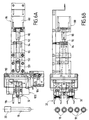
- FIG. 4 we now refer jointly to Figures 4 and 5 for describe the means of agitation 30.
- These include a support 86 which carries an electric motor 88, dr type not step, having a shaft 90 which extends along a horizontal axial direction X-X which is perpendicular to the direction of translation of the cassettes on the means of transfer 10, i.e. perpendicular to the path defined by the transfer means 10.
- the shaft 90 carries a screw 92 (threaded axis) cooperating with a nut 94 to constitute together a mechanism 96 of the type screw / nut ( Figures 4 and 5).
- Nut 94 is attached to a sleeve 95 guided in a flange 98 and is connected to a movable head 100 which carries the two gripping members 32.
- the electric motor 88 can be rotated, in one way or the other, under defined conditions, for selectively perform either the translational displacement of the movable head 100 in the direction of the axis X-X, that is to say its displacement in rotation around this axis.
- the stirring means 30 further comprise a stop 102 which consists of a lever 104 pivotally mounted around an axis 106 and actuated via a electromagnet 108.
- the lever 104 is able to cooperate with a disc 110 secured to the movable head 100 and provided with a notch 112.
- This stop member can be placed selectively either in a locking position in which the moving head 100 is immobilized in translation, either in a unlocking position, in which this movable head is integral with the nut in translation and in rotation.
- the motor 88 can be rotated in a direction V corresponding to the screwing, which allows the nut to be brought closer 94 (and therefore the moving head 100) of the motor 88, the moving head being immobilized in rotation by locking means.
- These the latter are composed of a bearing 132 and a groove 133 and will be described in detail later with reference to the figure 6. This movement thus allows the moving head to be moved away 100 of a cassette disposed on the transfer means.
- the motor 88 can also be driven in a corresponding direction D when unscrewing which removes nut 94 (and therefore the head mobile 100) of motor 88, this mobile head still being immobilized in rotation by the locking means 132 and 133.
- this movement allows the moving head to be brought closer 100 of the cassette disposed on the transfer means.
- each of the gripping members 32 comprises two bodies of clamp 114 each of which carries two jaws 116 and is mounted pivoting around an axis 118.
- Each gripper body defines a cam path 120 of selected shape which is intended for cooperate with a cam finger 121.
- the device comprises here four cam fingers 121 carried by axes 122 on a H-shaped support 124 mounted at the end 126 of a rod 128, itself mounted at the end of the sleeve 95.
- Rod 128 is slidable axially and in translation in an opening 129 of the disc 110, while its end 126 is able to slide in an opening 134 of the movable head.
- Rod 128 includes two flats 131, one of which comes to rest on a base 135 of the movable head 100, which allows to ensure or not a integral in rotation with the rod 128 and the head 100 according to their mutual axial position.
- the movable head 100 In the position of Figures 6A and 6B, the movable head 100 is in a position away from the cassette and therefore from the tubes of the latter.
- the coupling mechanism is near a stop position end of tightening.
- the aforementioned blocking means are composed of the bearing 132 which is integral with the sleeve 95 and which cooperates with the groove 133 of the support. These means realize a blockage in translation only or in rotation only.
- the moving head 100 approaches the cassette and therefore the tubes of the latter.
- the head abuts against a sheet before (not shown) which will then intervene during the replace the tube in the cassette.
- the head reaches thus in the position of FIGS. 7A and 7B, in which the jaws 116 of the gripping members are open for each time grab a tube from the cassette.
- the stop member 102 is actuated to place the lever 104 in the locking position as shown in dotted line (reference 104 '). This will block the head in the axial direction.
- the motor 88 is activated in the direction of screwing, which first causes the pivoting gripping organs and the approximation of their respective jaws to grasp a tube of the cassette.
- the locking means are brought back to the position of unlocking, as shown in FIGS. 8A and 8B, and continues the rotation of the motor 88 in the direction of screwing this which allows the moving head to be moved away from the cassette, the grippers holding a tube each time. During this movement, the moving head remains immobilized in rotation because the bearing 132 remains engaged in the throat 133.
- the means agitation extract two tubes each time from the cassette to shake them and then replace them in the cassette.
- the cassette is advanced, on the means of transfer, according to a chosen distance which is defined by the stepper motor 84 which activates the movement of the carriage 60.
- the tubes, previously agitated, are then brought, one to one, opposite the sampling means 34, which will be described later.
- the carriage mechanically actuates the ejection means 38.
- the carriage include a tilting member 136 (FIG. 1) mounted pivoting about an axis that extends parallel to the direction of the transfer means and which has a ramp 138 against which the carriage 60 cooperates for perform a pivoting movement of the tilting member.
- This the latter has two 140 pushers which support against the cassette to move it on the plate 36 in the direction of arrow F2. The cassettes are thus, after analysis, received in stack on the plate 36 of the means of unloading.
- the latter is disposed near the transfer means 10 and is suitable for receiving at least one tube 18, outside the presence of a cassette on the transfer means. he comprises a head 142 mounted to rotate and tilt and likely to be placed in different indexed positions. This head has housings 144 adapted for receive tubes of different dimensions.
- the head 142 can be placed in an inclined position, as shown in Figure 9, authorizing the loading of minus one tube in a suitable housing. Then this head is tilted to a vertical position, as shown on the Figure 10, in which the tube 18 is vertical for a operation to take a sample of blood product. As can be seen in Figures 9 and 10, the head can be rotated in different indexed positions in which the housing which carries the tube to be analyzed is located opposite the sampling means 34.
- Figure 11 we now refer to Figure 11 to describe the general structure of the sampling means. These latter include a carriage 146 movable in horizontal translation in a direction orthogonal to that of the means of transfer.
- This carriage 146 carries a piercer and a sampling needle associated (designated as a whole by the reference 148) and can be placed over a tube with a stopper is to be pierced.
- the piercer and the needle are then moved vertically from top to bottom to drill the tube cap and suction of a total amount sample.
- the sampling needle is connected to a suitable suction pump (not shown). Then the needle and the piercer are raised upwards and the carriage is moved so as to move away to come distribute fractions of the sample taken from different tanks 150 where a fraction of the sample is at each time mixed with a suitable reagent for analysis.
- sampling means can be carried out in accordance with the teachings of document EP-A-0 634 660.
- these means of withdrawal include advantageously cleaning means for cleaning the needle before and after each sampling operation.
- the stirring means provided for this purpose are less bulky and can be more easily integrated into the device of the invention.
- the device of the invention also offers the advantage that tubes can be loaded or unloaded in cassettes either laterally or vertically, in particular by the top.
- the invention finds particular application to analyzers hematological, such as those used in laboratories for analysis.
Abstract
Description
L'invention se rapporte aux analyseurs hématologiques destinés à analyser automatiquement des échantillons de produits sanguins.The invention relates to hematological analyzers intended to automatically analyze samples of blood products.
Elle concerne plus particulièrement un dispositif de traitement d'échantillons de produits sanguins contenus dans des tubes obturés par des bouchons et regroupés dans des cassettes, et comprenant des moyens d'agitation propres à agiter les tubes, ainsi que des moyens de prélèvement propres à prélever au moins un échantillon dans un tube préalablement agité.It relates more particularly to a treatment device samples of blood products contained in tubes closed by plugs and grouped in cassettes, and comprising stirring means suitable for stirring the tubes, as well as sampling means specific to take at least one sample from a tube beforehand stirred.
De tels dispositifs sont conçus pour agiter le tube afin de mélanger les constituants du produit sanguin qu'il contient et pour prélever ensuite un échantillon dont la composition est homogène et représentative du produit sanguin à analyser.Such devices are designed to agitate the tube in order to mix the constituents of the blood product it contains and to then take a sample whose composition is homogeneous and representative of the blood product to be analyzed.
On connaít en particulier, d'après US-A-3 231 244, un dispositif automatique de mélange de produits sanguins, qui comprend un tambour rotatif muni de logements propres à maintenir des tubes contenant de tels produits. Les tubes sont disposés radialement par rapport à l'axe de rotation du tambour, en sorte que leurs bouchons respectifs soient dirigés vers l'extérieur. En fait, il s'agit seulement d'un dispositif d'agitation qui présente l'inconvénient que les tubes doivent être chargés manuellement sur le tambour puis extraits manuellement du tambour, une fois l'agitation réalisée.We know in particular, from US-A-3,231,244, a automatic blood product mixing device, which includes a rotary drum with housings suitable for maintain tubes containing such products. The tubes are arranged radially with respect to the axis of rotation of the drum, so that their respective caps are directed outwards. In fact, it is only a stirring device which has the disadvantage that the tubes must be loaded manually onto the drum and then manually removed from the drum, after agitation performed.
On connaít aussi, d'après EP-A-0 061 317, un dispositif d'agitation et de prélèvement d'échantillons de produits sanguins, dans lequel les tubes contenant les produits sont regroupés dans des cassettes, lesquelles sont disposées manuellement dans un tambour rotatif. Ce dernier a pour fonction d'assurer par rotation le mélange des produits sanguins et d'immobiliser une cassette en position sensiblement verticale pour que les tubes qu'elle contient soient immobilisés avec leurs bouchons vers le bas. Une station de prélèvement est prévue pour prélever un échantillon dans un tube dans une cassette après perçage du bouchon du tube. Après analyse, les cassettes sont extraites manuellement du tambour.We also know, from EP-A-0 061 317, a device agitation and product sample collection in which the tubes containing the products are grouped in cassettes, which are arranged manually in a rotating drum. The latter has function of ensuring the mixing of products by rotation and immobilize a cassette in a substantially position vertical so that the tubes it contains are immobilized with their caps down. A station sampling is planned to take a sample from a tube in a cassette after drilling the tube cap. After analysis, the cassettes are extracted manually from the drum.
Le principal inconvénient de ce dispositif connu est qu'il ne peut pas faire tourner le tambour, et donc agiter l'ensemble des tubes, pendant l'opération de prélèvement proprement dite.The main drawback of this known device is that it does not can't turn the drum, and therefore shake the whole tubes, during the actual sampling operation called.
On connaít aussi, d'après FR-A-2 730 315, un dispositif d'agitation et de prélèvement d'échantillons de produits sanguins dans des tubes regroupés dans des cassettes. Ce dispositif connu comprend un support de cassette propre à maintenir et à agiter au moins une cassette chargée d'au moins un tube ainsi qu'au moins une station de prélèvement propre à percer le bouchon du tube pour prélever l'échantillon. Du fait que ce prélèvement s'effectue dans un tube, en dehors de la cassette, il n'est plus nécessaire de prévoir des moyens pour bloquer le support en rotation pendant le prélèvement.We also know, from FR-A-2 730 315, a device agitation and product sample collection blood in tubes grouped in cassettes. This known device comprises a cassette holder suitable for maintain and shake at least one cassette loaded with at least one tube and at least one sampling station suitable for piercing the tube cap to take the sample. Because this sample is taken in a tube, in outside the cassette, it is no longer necessary to plan means for locking the support in rotation during the sample.
Ce dispositif connu est d'une grande complexité mécanique, ce qui engendre un surcoût.This known device is of great mechanical complexity, which which generates an additional cost.
On connaít en outre, d'après FR-A-2 692 358, un dispositif de transfert, d'agitation et de prélèvement d'échantillons de produits sanguins qui comprend un chariot mobile propre à extraire une cassette garnie de tubes d'échantillons dans un réceptacle de stockage et à amener la cassette dans un chariot rotatif. Ce dernier assure le mélange des échantillons et s'immobilise pour autoriser le prélèvement des tubes de la cassette par une station de prélèvement.We also know, from FR-A-2 692 358, a device for transfer, agitation and sampling of blood products which includes a mobile cart specific to extract a cassette filled with sample tubes in a storage receptacle and to bring the cassette into a rotary cart. The latter ensures the mixing of samples and stops to authorize the removal of the tubes of the cassette by a sampling station.
Ce dispositif présente sensiblement les mêmes inconvénients que ceux mentionnés précédemment. This device has substantially the same disadvantages than those mentioned earlier.
L'invention a notamment pour but de surmonter les inconvénients précités.The object of the invention is in particular to overcome the drawbacks supra.
Elle vise en particulier à proposer un dispositif de traitement d'échantillons de produits sanguins contenus dans des tubes regroupés dans des cassettes, grâce auquel l'agitation des tubes s'effectue en dehors des cassettes, ce qui évite d'avoir à agiter les cassettes proprement dites.It aims in particular to propose a treatment device samples of blood products contained in tubes grouped in cassettes, thanks to which agitation tubes are made outside the cassettes, which avoids having to shake the cassettes themselves.
L'invention vise aussi à procurer un tel dispositif de traitement qui permet d'agiter un tube en dehors de la cassette, et de prélever ensuite un échantillon de produits sanguins dans le tube préalablement replacé dans la cassette.The invention also aims to provide such a device for treatment which allows a tube to be agitated outside the cassette, and then take a sample of products blood in the tube previously replaced in the cassette.
Elle vise également à procurer un dispositif du type précité, dans lequel les cassettes offrent différentes possibilités de chargement ou de déchargement des tubes.It also aims to provide a device of the aforementioned type, in which the cassettes offer different possibilities of loading or unloading of tubes.
En outre l'invention vise à procurer un tel dispositif qui peut être facilement intégré dans une chaíne de plusieurs appareils d'analyse de sang.Furthermore, the invention aims to provide such a device which can be easily integrated into a chain of several blood analysis apparatus.
L'invention propose à cet effet un dispositif de traitement du type défini en introduction, lequel comprend des moyens de transfert propres à déplacer individuellement les cassettes suivant un trajet déterminé, et dans lequel les moyens d'agitation comprennent au moins un organe de préhension propre à saisir au moins un tube choisi dans une cassette immobilisée sur le trajet, éloigner ledit tube de la cassette, l'agiter et le replacer dans la cassette, et dans lequel les moyens de prélèvement comprennent au moins une aiguille propre à prélever une quantité donnée d'échantillon dans le tube préalablement agité et replacé dans la cassette.The invention provides for this purpose a treatment device of the type defined in the introduction, which includes means for transfer suitable for individually moving the cassettes along a determined route, and in which the means of agitation include at least one gripping member suitable for gripping at least one tube chosen from a cassette immobilized on the path, move said tube away from the cassette, shake it and put it back in the cassette, and in which the sampling means comprise at least one needle suitable for taking a given quantity of sample from the tube previously shaken and replaced in the cassette.
Ainsi, le dispositif de l'invention réalise l'agitation des tubes après leur extraction de la cassette et le prélèvement des échantillons dans les tubes qui, une fois agités, ont été replacés dans la cassette. Thus, the device of the invention performs the agitation of tubes after their extraction from the cassette and the sampling samples in the tubes which, after shaking, were replaced in the cassette.
Ceci évite par conséquent d'agiter l'ensemble de la cassette comme dans la plupart des dispositifs de la technique antérieure.This therefore avoids shaking the entire cassette as in most technical devices earlier.
Il en résulte aussi l'avantage que les cassettes peuvent être déplacées sur un trajet choisi, en particulier un trajet linéaire favorisant ainsi l'intégration du dispositif de l'invention dans une chaíne d'appareils hématologiques.This also results in the advantage that the cassettes can be moved on a chosen path, in particular a path linear thus promoting the integration of the the invention in a chain of hematological devices.
En outre, du fait que le chargement et le déchargement des tubes s'effectuent dans une cassette, qui est déplacée par des moyens de transfert, ces opérations peuvent être effectuées de différentes manières, en particulier par le dessus et par le côté de la cassette.In addition, since the loading and unloading of tubes are made in a cassette, which is moved by transfer means, these operations can be performed in different ways, especially from above and by the side of the cassette.
Par ailleurs, du fait que les moyens d'agitation s'appliquent à un ou plusieurs tubes, et non pas à une cassette, il en résulte une diminution de l'encombrement du dispositif, ce qui contribue à son intégration dans une chaíne de plusieurs appareils.Furthermore, because the means of agitation apply to one or more tubes, and not to a cassette, it results in a reduction in the size of the device, this which contributes to its integration into a chain of several devices.
Dans une forme de réalisation préférée, les moyens de transfert comprennent un chariot propre à être solidarisé à une cassette par l'intermédiaire d'un doigt escamotable et des moyens de déplacement propres à déplacer le chariot entre des positions définies le long du trajet.In a preferred embodiment, the means of transfer include a clean cart to be secured to a cassette by means of a retractable finger and movement means suitable for moving the carriage between defined positions along the route.
Selon une autre caractéristique de l'invention, les tubes sont disposés verticalement dans la cassette et dans l'alignement du trajet, tandis que les moyens d'agitation sont propres à extraire latéralement au moins un tube de la cassette et à le replacer latéralement dans la cassette après agitation.According to another characteristic of the invention, the tubes are arranged vertically in the cassette and aligned of the journey, while the means of agitation are suitable for laterally extracting at least one tube from the cassette and replace it laterally in the cassette after agitation.
La cassette comprend avantageusement des clips élastiques en U qui autorisent l'extraction d'un tube et sa remise en place par un déplacement latéral parallèle à lui-même ou par un déplacement axial du tube dans l'axe de ce dernier. The cassette advantageously comprises elastic clips in U which authorize the extraction of a tube and its replacement by a lateral displacement parallel to itself or by a axial displacement of the tube in the axis of the latter.
Il en résulte l'avantage que les tubes peuvent être chargés ou déchargés soit sur le côté de la cassette, soit par le dessus de la cassette.This results in the advantage that the tubes can be loaded or unloaded either on the side of the cassette or by the above the cassette.
Selon une autre caractéristique de l'invention, le ou chaque organe de préhension est propre à être entraíné en rotation continue par un moteur, de manière à effectuer une agitation continue par retournement complet du tube.According to another characteristic of the invention, the or each gripping member is adapted to be rotated continues by a motor, so as to effect agitation continues by completely inverting the tube.
Dans une forme de réalisation préférée, les moyens d'agitation comprennent une tête mobile qui porte le ou les organes de préhension et qui est propre à être entraínée en translation ou en rotation par l'intermédiaire d'un mécanisme d'accouplement relié à un moteur à deux sens de rotation.In a preferred embodiment, the stirring means include a movable head which carries the organ (s) gripping and which is suitable for being driven in translation or in rotation through a coupling mechanism connected to a motor with two directions of rotation.
Avantageusement, ce mécanisme d'accouplement comprend une vis et un écrou et est propre à être entraíné en rotation par le moteur de manière sélective, soit dans un sens de vissage pour éloigner la tête mobile de la cassette, soit dans un sens de dévissage pour rapprocher la tête mobile de la cassette, la tête mobile étant alors bloquée en rotation dans une orientation choisie par des moyens de blocage placés dans une position de verrouillage.Advantageously, this coupling mechanism comprises a screw and a nut and is suitable for being rotated by the motor selectively, either in a screwing direction to move the movable head away from the cassette, either in a unscrewing direction to bring the moving head closer to the cassette, the movable head then being locked in rotation in an orientation chosen by blocking means placed in a locking position.
On prévoit avantageusement que ces moyens de blocage sont propres à être placés en outre dans une position de déverrouillage lorsque le mécanisme d'accouplement est parvenu à une position de butée en fin de vissage, ce qui permet un mouvement de rotation de la tête mobile pour agiter le ou les tubes.It is advantageously provided that these blocking means are suitable for being additionally placed in an unlocking position when the coupling mechanism has reached a stop position at the end of screwing, which allows a rotational movement of the movable head to agitate the tubes.
De préférence, le mouvement de rotation de la tête mobile est une rotation continue et complète dans le sens du vissage du mécanisme d'accouplement.Preferably, the rotational movement of the movable head is a continuous and complete rotation in the direction of screwing of the coupling mechanism.
Selon une autre caractéristique de l'invention, le dispositif comprend un mécanisme d'ouverture et de fermeture de l'organe de préhension qui est propre à être actionné en translation par le mécanisme d'accouplement, une fois ce dernier parvenu à une position de butée en fin de dévissage, la tête mobile étant immobilisée en rotation par les moyens de blocage.According to another characteristic of the invention, the device includes a mechanism for opening and closing the organ gripping which is adapted to be actuated in translation by the coupling mechanism, once it has reached at a stop position at the end of unscrewing, the movable head being immobilized in rotation by the locking means.
L'organe de préhension comprend avantageusement deux corps de pince dont chacun porte au moins une mâchoire et définit un chemin de came, ainsi qu'un moyen de rappel élastique reliant les deux corps de pince pour solliciter les mâchoires l'une vers l'autre, le mécanisme d'ouverture et de fermeture comprenant des doigts de came déplacés en translation par le mécanisme d'accouplement et coopérant respectivement avec les chemins de came.The gripping member advantageously comprises two bodies of forceps each of which carries at least one jaw and defines a cam path, as well as an elastic return means connecting the two gripper bodies for biasing the jaws one towards each other, the opening and closing mechanism comprising cam fingers moved in translation by the coupling mechanism and cooperating respectively with the cam paths.
Selon une autre caractéristique de l'invention, le dispositif comprend un moyen de chargement manuel, encore appelé poste d'urgence, qui est disposé à proximité des moyens de transfert pour recevoir au moins un tube et placer ce tube sur le trajet des moyens de transfert et des moyens de prélèvement, en dehors de la présence d'une cassette, en vue du prélèvement d'un échantillon par les moyens de prélèvement.According to another characteristic of the invention, the device includes manual loading means, also called post emergency, which is arranged near the transfer means to receive at least one tube and place this tube on the path of the transfer means and of the withdrawal means, apart from the presence of a cassette, for the purpose of sampling of a sample by the means of sampling.
Ce moyen de chargement manuel comprend avantageusement une tête rotative et basculante ayant des positions indexées et comportant des logements propres à recevoir des tubes de dimensions différentes.This manual loading means advantageously comprises a rotating and tilting head having indexed positions and comprising housings suitable for receiving tubes of different dimensions.
Selon encore une autre caractéristique de l'invention, les moyens de prélèvement comprennent un chariot supportant un perceur et l'aiguille de prélèvement, et ce chariot est déplaçable entre une position de prélèvement, en laquelle le perceur est propre à percer le bouchon du tube et l'aiguille de prélèvement à prélever une quantité totale d'échantillon, et au moins une position de distribution, en laquelle l'aiguille de prélèvement est propre à refouler ladite quantité totale d'échantillon, ou une fraction de celle-ci, dans un réceptacle, tel qu'un bac de réactif.According to yet another characteristic of the invention, the sampling means include a carriage supporting a piercer and the sampling needle, and this carriage is movable between a picking position, in which the piercer is suitable for piercing the tube plug and the needle of sampling to take a total quantity of sample, and at least one distribution position, in which the sampling needle is capable of discharging said total amount of sample, or a fraction thereof, in a receptacle, such as a reagent container.
Avantageusement, le dispositif comprend en outre un poste de chargement des cassettes et un poste de déchargement des cassettes placés respectivement en amont et en aval des moyens de transfert.Advantageously, the device further comprises a station for cassette loading and unloading station cassettes placed respectively upstream and downstream of means of transfer.
Dans la description qui suit, faite seulement à titre d'exemple, on se réfère aux dessins annexés, sur lesquels :
- la figure 1 est une vue de dessus d'un dispositif de traitement selon l'invention ;
- les figures 2A et 2B sont des vues en perspective d'une cassette propre à être utilisée dans le dispositif de la figure 1 ;
- la figure 3 est une vue en perspective des moyens de transfert et du poste de chargement manuel ;
- la figure 4 est une vue en perspective des moyens d'agitation ;
- la figure 5 est une vue en perspective éclatée des moyens d'agitation de la figure 4 ;
- les figures 6A, 7A et 8A sont des vues de côté des moyens d'agitation dans différentes phases de fonctionnement ;
- les figures 6B, 7B et 8B sont des vues de dessus correspondant respectivement aux figures 6A, 7A et 8A ;
- la figure 9 est une vue partielle en perspective du dispositif de transfert montrant le poste de chargement manuel dans une position inclinée pour le chargement ;
- la figure 10 est une vue analogue à la figure 9 dans laquelle le poste de chargement est en position redressée ; et
- la figure 11 est une vue de dessus des moyens de prélèvement.
- Figure 1 is a top view of a processing device according to the invention;
- Figures 2A and 2B are perspective views of a cassette suitable for use in the device of Figure 1;
- Figure 3 is a perspective view of the transfer means and the manual loading station;
- Figure 4 is a perspective view of the stirring means;
- Figure 5 is an exploded perspective view of the stirring means of Figure 4;
- Figures 6A, 7A and 8A are side views of the stirring means in different operating phases;
- Figures 6B, 7B and 8B are top views corresponding respectively to Figures 6A, 7A and 8A;
- Figure 9 is a partial perspective view of the transfer device showing the manual loading station in an inclined position for loading;
- Figure 10 is a view similar to Figure 9 in which the loading station is in the upright position; and
- Figure 11 is a top view of the sampling means.
Le dispositif représenté dans son ensemble sur la figure 1
comprend des moyens de transfert 10 qui permettent de
déplacer individuellement des cassettes 12 suivant un trajet
déterminé, ici un trajet rectiligne, entre un poste de
chargement 14 et un poste de déchargement 16. Ces postes 14
et 16 sont placés respectivement en amont et en aval des
moyens de transfert 10.The device shown as a whole in Figure 1
includes transfer means 10 which allow
individually move
Les cassettes 12, qui seront décrites en détail plus loin,
supportent chacune une pluralité de tubes 18, dans l'exemple
dix tubes, qui renferment chacun un produit sanguin et sont
fermés chacun par un bouchon 20 (figure 2).
Le poste de chargement 14 comprend un plateau de chargement
22 disposé horizontalement, et propre à recevoir une série de
cassettes contenant des tubes dont les produits sont à
analyser. Le poste de chargement 14 comprend des moyens
d'avancement constitués ici par deux taquets poussoirs 24
déplaçables en synchronisme dans la direction de la flèche F1
pour acheminer les cassettes une à une vers les moyens de
transfert 10. Ces taquets poussoirs 24 sont déplacés en
synchronisme par des courroies sans fin 26, entraínées
simultanément, et ils comprennent chacun un doigt 28 venant
coopérer avec une extrémité de la cassette. Ces taquets
poussoirs viennent ainsi agir sur la dernière cassette
faisant partie de la pile à analyser.The
Entre le poste de chargement 14 et le poste de déchargement
16 sont placés des moyens d'agitation désignés dans leur
ensemble par la référence 30. Ces moyens d'agitation comprennent,
dans l'exemple, deux organes de préhension 32 propres
à saisir deux tubes choisis dans une cassette 12 immobilisée
sur le trajet des moyens de transfert.Between loading
Comme on peut le voir sur la figure 1, une cassette 12 se
trouve immobilisée sur le trajet entre le poste de chargement
14 et le poste de déchargement 16. Les moyens d'agitation 30,
qui seront décrits en détail plus loin, permettent, dans
l'exemple, de saisir deux tubes de la cassette, de les
éloigner de la cassette, puis de les agiter et enfin de les
replacer dans la cassette.As can be seen in Figure 1, a
Entre les moyens d'agitation 30 et le poste de déchargement
16 sont disposés des moyens de prélèvement 34 qui sont
représentés schématiquement sur la figure 1 et seront décrits
en détail plus loin. Ces moyens de prélèvement sont conçus
pour prélever un échantillon de produit sanguin dans un tube
qui a été préalablement agité et replacé dans la cassette.
Cet échantillon est ensuite analysé par des moyens qui seront
décrits plus loin.Between the stirring means 30 and the unloading
Une fois que tous les tubes de la cassette ont été agités et
qu'ils ont fait l'objet d'un prélèvement d'échantillon, la
cassette dans son ensemble est déplacée par les moyens de
transfert 10 vers le poste de déchargement 16.Once all the tubes in the cassette have been shaken and
that they were sampled, the
cassette as a whole is moved by means of
Ce dernier comprend un plateau de déchargement 36 qui s'étend
à l'horizontale et qui est prévu pour recevoir les cassettes
12, lesquelles ont été acheminées à partir des moyens de
transfert 10 grâce à des moyens d'éjection 38, qui seront
décrits en détail plus loin.The latter comprises an unloading
On se réfère maintenant aux figures 2A et 2B pour décrire en
détail une cassette 12 dans un mode de réalisation préféré de
l'invention.We now refer to FIGS. 2A and 2B to describe in
detail of a
Cette cassette 12, en forme de râtelier, comprend une paroi
de fond 40 de forme générale rectangulaire, à laquelle se
rattache une paroi latérale verticale 42, également de forme
rectangulaire, qui s'étend sur la même longueur que la paroi
de fond 40.This
La paroi latérale 42 porte, du côté intérieur, une pluralité
de clips élastiques 44 en forme de U qui sont prévus pour
maintenir individuellement un tube 18 dans une position
verticale. On peut ainsi disposer dix tubes (dans cet
exemple) qui sont dans l'alignement de la direction longitudinale
DL de la cassette. Les tubes 18 comprennent chacun un
fond 46 qui est reçu dans un logement 48 aménagé dans la
paroi de fond 40 de la cassette.The
Les tubes possèdent une ouverture qui, dans l'exemple est
dirigée vers le haut et est obturée par un bouchon 20, lequel
est susceptible d'être percé par un perceur (non représentée)
faisant partie des moyens de prélèvement 34.The tubes have an opening which, in the example is
directed upwards and is closed by a
Comme on peut le constater sur la figure 2A, cette cassette
a pour particularité de permettre un chargement et déchargement
des tubes par le côté, c'est-à-dire dans une direction
horizontale et perpendiculaire à la paroi latérale 42.
Autrement dit, l'extraction d'un tube et sa remise en place
peuvent être effectuées par un déplacement latéral, le tube
restant parallèle à lui-même.As can be seen in Figure 2A, this cassette
has the particularity to allow loading and unloading
tubes from the side, i.e. in one direction
horizontal and perpendicular to the
Egalement, les clips 44 autorisent un déplacement axial du
tube dans l'axe de ce dernier, c'est-à-dire un déplacement
vertical, perpendiculaire à la paroi de fond 40.Also, the
Conformément à l'invention, il est possible de réaliser différents types de cassettes en fonction des dimensions des tubes à recevoir, l'essentiel étant que le pas défini entre les tubes reste le même.According to the invention, it is possible to carry out different types of cassettes depending on the dimensions of the tubes to receive, the main thing being that the pitch defined between the tubes stays the same.
La paroi de fond 40 de la cassette est munie de quatre
encoches 50 (figures 2A et 2B) propres à se positionner sur
deux butées rétractables (non représentées), aménagées dans
le plateau de chargement 22, afin que l'utilisateur ne puisse
pas pousser manuellement la cassette dans les moyens de
transfert.The
En outre cinq logements 51 sont aménagés sous la cassette
(figure 2B) pour coopérer avec les moyens de transfert, comme
on le verra plus loin, et réaliser ainsi l'entraínement de la
cassette suivant un trajet défini.In addition, five
Les moyens de transfert 10, tels que représentés à la figure
3, comprennent deux supports d'extrémité 52 et 54 entre
lesquels s'étendent un rail horizontal de guidage 56 sur
lequel vient glisser la paroi de fond 40 d'une cassette et un
autre rail horizontal de guidage 58, disposé au-dessus du
rail de guidage 56, et contre lequel vient s'appliquer
latéralement la paroi latérale 42 de la cassette. Les rails
56 et 58 sont chacun réalisés en deux parties. La cassette
peut être ainsi guidée en translation avec sa paroi de fond
40 et sa paroi latérale 42 maintenues en appui respectivement
sur les rails 56 et 58.The transfer means 10, as shown in the figure
3, include two end supports 52 and 54 between
which extend a
Le déplacement en translation d'une cassette est effectué à
l'aide d'un chariot 60 déplaçable en translation le long d'un
organe de guidage rectiligne 62, tel qu'une tige, qui s'étend
parallèlement au rail 56. Les moyens de transfert 10 comprennent
une courroie sans fin 64, qui est couplée au chariot 60
et qui est propre à déplacer ce chariot en translation, dans
un sens ou dans un autre, entre des positions définies le
long du trajet.The translational movement of a cassette is carried out at
using a
Le chariot 60 est muni d'un doigt escamotable 66 couplé à un
levier 68, en forme de L, monté pivotant autour d'un axe 70
et actionné par un électro-aimant 72. Ce doigt escamotable
est propre à être déplacé verticalement vers le haut pour
venir s'engager dans l'un ou l'autre des logements 51
aménagés sous la cassette. Il peut aussi être déplacé
verticalement vers le bas pour s'extraire de la cassette et
permettre, en particulier, l'éjection de cette dernière sur
le plateau de déchargement 36.The
Par ailleurs, le rail de guidage 58 porte deux butées mobiles
74, dont l'une au moins est propre à être actionnée lors du
déplacement de la cassette dans les moyens de transfert 10.Furthermore, the
A cet effet, la paroi latérale 42 de la cassette comporte un
bord crénelé 78 dans lequel sont aménagées une série d'encoches
80 présentant le même pas que les tubes.To this end, the
Chacune des butées mobiles 74 est en outre propre à actionner
un capteur 76. A son état de repos, chaque butée mobile 74
est maintenue en position basse par un ressort et le capteur
76 est au repos.Each of the movable stops 74 is further adapted to actuate
a
Lors du déplacement latéral de la cassette, la butée 74 subit
un mouvement vertical ascendant provoqué par le bord crénelé
78 de la paroi 42 de la cassette 12, ce qui a pour effet
d'actionner le capteur 76. La butée 74 reprend son état
initial lorsqu'elle tombe dans une encoche 80, et le capteur
n'est plus actionné.During the lateral displacement of the cassette, the
La combinaison des informations en provenance des capteurs 76
actionnés par les butées est de nature à déterminer le
positionnement d'au moins une cassette dans les moyens de
transfert 10 et est aussi de nature à maintenir le positionnement
de la cassette lors des opérations de prélèvement,
d'agitation et de manipulation d'une seconde cassette par le
chariot 60.Combining information from
Comme on le voit sur les figures 1 et 3, à côté des moyens de
transfert 10 est placé un moyen de chargement manuel 82,
encore appelé poste d'urgence, qui est prévu pour recevoir au
moins un tube 18 et le placer sur le trajet des moyens de
transfert et des moyens de prélèvement, en dehors de la
présence d'une cassette, en vue du prélèvement d'un échantillon
par les moyens de prélèvement 34. Ce moyen de chargement
sera décrit en détail plus loin.As seen in Figures 1 and 3, next to the means of
La courroie sans fin 64 est entraínée en translation, dans un
sens ou dans l'autre, par un moteur 84, en particulier du
type pas à pas, ce qui permet de placer le chariot, et donc
la cassette, en une position choisie le long du trajet.The
On se réfère maintenant conjointement aux figures 4 et 5 pour
décrire les moyens d'agitation 30. Ces derniers comprennent
un support 86 qui porte un moteur électrique 88, dr type pas
à pas, présentant un arbre 90 qui s'étend suivant une
direction axiale horizontale X-X qui est perpendiculaire à la
direction de translation des cassettes sur les moyens de
transfert 10, c'est-à-dire perpendiculairement au trajet
défini par les moyens de transfert 10.We now refer jointly to Figures 4 and 5 for
describe the means of
L'arbre 90 porte une vis 92 (axe fileté) coopérant avec un
écrou 94 pour constituer ensemble un mécanisme 96 du type
vis/écrou (figures 4 et 5). L'écrou 94 est fixé à un manchon
95 guidé dans une bride 98 et est relié à une tête mobile 100
qui porte les deux organes de préhension 32.The
Le moteur électrique 88 peut être entraíné en rotation, dans
un sens ou dans l'autre, dans des conditions définies, pour
réaliser sélectivement soit le déplacement en translation de
la tête mobile 100 dans la direction de l'axe X-X, soit son
déplacement en rotation autour de cet axe.The
Les moyens d'agitation 30 comprennent en outre un organe de
butée 102 qui est constitué d'un levier 104 monté pivotant
autour d'un axe 106 et actionné par l'intermédiaire d'un
électro-aimant 108. Le levier 104 est propre à coopérer avec
un disque 110 solidaire de la tête mobile 100 et muni d'une
encoche 112. Cet organe de butée peut être placé sélectivement
soit dans une position de verrouillage en laquelle la
tête mobile 100 est immobilisée en translation, soit dans une
position de déverrouillage, dans laquelle cette tête mobile
est solidaire de l'écrou en translation et en rotation.The stirring means 30 further comprise a
Le moteur 88 peut être entraíné en rotation dans un sens V
correspondant au vissage, ce qui permet de rapprocher l'écrou
94 (et donc la tête mobile 100) du moteur 88, la tête mobile
étant immobilisée en rotation par des moyens de blocage. Ces
derniers sont composés d'un roulement 132 et d'une gorge 133
et seront décrits en détail plus loin en référence à la
figure 6. Ce mouvement permet ainsi d'éloigner la tête mobile
100 d'une cassette disposée sur les moyens de transfert.The
Le moteur 88 peut aussi être entraíné dans un sens D correspondant
au dévissage qui éloigne l'écrou 94 (et donc la tête
mobile 100) du moteur 88, cette tête mobile étant encore
immobilisée en rotation par les moyens de blocage 132 et 133. The
Ce mouvement permet au contraire de rapprocher la tête mobile 100 de la cassette disposée sur les moyens de transfert.On the contrary, this movement allows the moving head to be brought closer 100 of the cassette disposed on the transfer means.
Par ailleurs, lorsque le moteur 88 est actionné dans le sens
du vissage et que l'écrou 94 est venu en butée avec l'arbre
90 du moteur 88, et que les moyens de blocage 132 et 133 sont
amenés dans une position de déverrouillage, la rotation du
moteur dans le sens du vissage permet d'entraíner en rotation
la tête mobile 100, alors que cette dernière est éloignée de
la cassette, comme on le verra plus loin.Furthermore, when the
Comme on peut le voir plus particulièrement sur la figure 5,
chacun des organes de préhension 32 comprend deux corps de
pince 114 dont chacun porte deux mâchoires 116 et est monté
pivotant autour d'un axe 118. Chaque corps de pince définit
un chemin de came 120 de forme choisie qui est destiné à
coopérer avec un doigt de came 121. Le dispositif comprend
ici quatre doigts de came 121 portés par des axes 122 sur un
support 124 en forme de H monté à l'extrémité 126 d'une tige
128, elle-même montée à l'extrémité du manchon 95.As we can see more particularly in Figure 5,
each of the gripping
Par ailleurs, les deux mâchoires d'une même pince sont
sollicitées l'une vers l'autre par un ressort élastique de
rappel 130, permettant de s'adapter aux différents diamètres
de tubes utilisables. La tige 128 est propre à coulisser
axialement et en translation dans une ouverture 129 du disque
110, tandis que son extrémité 126 est propre à coulisser dans
une ouverture 134 de la tête mobile. La tige 128 comprend
deux méplats 131 dont l'un vient en appui sur une embase 135
de la tête mobile 100, ce qui permet d'assurer ou non une
solidarisation en rotation de la tige 128 et de la tête 100
en fonction de leur position axiale mutuelle.Furthermore, the two jaws of the same clamp are
biased towards each other by an elastic spring of
Ainsi, lorsque la tige 128 est déplacée en translation axiale
par rapport à la tête mobile 100, elle permet de réaliser
l'ouverture et la fermeture des mâchoires respectives 116 des
deux organes de préhension. Thus, when the
Le fonctionnement des moyens d'agitation sera maintenant
décrit en référence aux figures 6 à 8. Dans la position des
figures 6A et 6B, la tête mobile 100 est dans une position
éloignée de la cassette et donc des tubes de cette dernière.
Le mécanisme d'accouplement est près d'une position de butée
de fin de vissage. Les moyens de blocage précités sont
composés du roulement 132 qui est solidaire du manchon 95 et
qui coopère avec la gorge 133 du support. Ces moyens réalisent
un blocage en translation seule ou en rotation seule.The functioning of the stirring means will now be
described with reference to Figures 6 to 8. In the position of
Figures 6A and 6B, the
Si l'on actionne le moteur 88 dans le sens du dévissage, la
tête mobile 100 se rapproche de la cassette et donc des tubes
de cette dernière. La tête vient en butée contre une tôle
avant (non représentée) qui interviendra ensuite lors de la
remise en place du tube dans la cassette. La tête parvient
ainsi à la position des figures 7A et 7B, dans laquelle les
mâchoires 116 des organes de préhension sont ouvertes pour
venir à chaque fois saisir un tube de la cassette. Ensuite,
on actionne l'organe de butée 102 pour placer le levier 104
dans la position de verrouillage telle que représentée en
pointillés (référence 104'). Ceci permet de bloquer la tête
dans la direction axiale. On actionne ensuite le moteur 88
dans le sens du vissage, ce qui provoque d'abord le pivotement
des organes de préhension et le rapprochement de leurs
mâchoires respectives pour saisir à chaque fois un tube de la
cassette.If the
Ensuite, on ramène les moyens de blocage dans la position de
déverrouillage, comme montré sur les figures 8A et 8B, et on
poursuit la rotation du moteur 88 dans le sens du vissage ce
qui permet d'éloigner la tête mobile de la cassette, les
organes de préhension maintenant à chaque fois un tube.
Pendant ce déplacement, la tête mobile reste immobilisée en
rotation du fait que le roulement 132 reste engagé dans la
gorge 133.Then, the locking means are brought back to the position of
unlocking, as shown in FIGS. 8A and 8B, and
continues the rotation of the
Lorsque l'on parvient en fin du mouvement de vissage, c'est-à-dire
en butée entre l'écrou 94 et l'arbre 90, le roulement
132 s'échappe de la gorge 133, si bien que la tête mobile 100
n'est plus immobilisée en rotation.When you reach the end of the screwing movement, i.e.
in abutment between
On peut alors entraíner en rotation le moteur, de manière continue, dans le sens du vissage ce qui provoque la rotation de la tête mobile et par conséquent l'agitation des deux tubes qu'elle porte.We can then rotate the motor, so continuous, in the direction of screwing which causes rotation of the moving head and therefore the agitation of the two tubes she wears.
Ces deux tubes sont alors agités par un mouvement de rotation continue sur 360°, ce qui permet d'assurer une meilleure agitation que par un mouvement pendulaire.These two tubes are then agitated by a rotational movement continuous 360 °, which ensures better agitation only by a pendulum movement.
Après agitation, les tubes sont remis en place dans la cassette.After stirring, the tubes are replaced in the cassette.
Ainsi, grâce au moteur 88, au mécanisme d'accouplement 96, à
l'organe de butée 102 et aux moyens de blocage constitués par
le roulement 132 et la gorge 133, on peut réaliser différents
mouvements, à savoir mouvement en translation de la tête
mobile 100 dans la direction axiale, dans un sens ou dans
l'autre, et mouvement de rotation de cette tête mobile pour
assurer l'agitation des tubes.Thus, thanks to the
On remarquera que, dans l'exemple de réalisation, les moyens d'agitation viennent extraire à chaque fois deux tubes de la cassette pour les agiter et les replacer ensuite dans la cassette.It will be noted that, in the embodiment, the means agitation extract two tubes each time from the cassette to shake them and then replace them in the cassette.
Comme cette cassette possède en tout dix tubes, il suffit au minimum de cinq opérations pour réaliser l'agitation de l'ensemble des dix tubes. On préfère cependant agiter chaque tube deux fois : d'abord le tube N°1 tout seul, puis le tube N°2 tout seul, puis les tubes N°s 1 et 3 ensemble, puis les tubes N°s 2 et 4 ensemble, et ainsi de suite.As this cassette has a total of ten tubes, it suffices to minimum of five operations to agitate all ten tubes. However, we prefer to shake each tube twice: first tube N ° 1 alone, then the tube N ° 2 alone, then tubes N ° 1 and 3 together, then tubes No. 2 and 4 together, and so on.
A chaque fois, la cassette est avancée, sur les moyens de
transfert, selon une distance choisie qui est définie par le
moteur pas à pas 84 qui actionne le déplacement du chariot
60. Each time, the cassette is advanced, on the means of
transfer, according to a chosen distance which is defined by the
Les tubes, préalablement agités, sont ensuite amenés, un à un, en regard des moyens de prélèvement 34, qui seront décrits plus loin.The tubes, previously agitated, are then brought, one to one, opposite the sampling means 34, which will be described later.
Après prélèvement dans les dix tubes de la cassette, cette
dernière est amenée en regard du poste déchargement 16 où le
chariot actionne mécaniquement les moyens d'éjection 38. Ces
derniers comprennent un organe basculant 136 (figure 1) monté
pivotant autour d'un axe qui s'étend parallèlement à la
direction des moyens de transfert et qui possède une rampe
138 contre laquelle vient coopérer le chariot 60 pour
réaliser un mouvement de pivotement de l'organe basculant. Ce
dernier est muni de deux poussoirs 140 qui viennent appuyer
contre la cassette pour la déplacer sur le plateau 36 dans la
direction de la flèche F2. Les cassettes se trouvent ainsi,
après analyse, reçues en pile sur le plateau 36 des moyens de
déchargement.After sampling from the ten tubes of the cassette, this
last is brought next to the unloading
On se réfère maintenant aux figures 9 et 10 pour décrire plus en détail le moyen de chargement manuel 82, encore appelé poste d'urgence.We now refer to Figures 9 and 10 to describe more in detail the manual loading means 82, also called emergency post.
Ce dernier est disposé à proximité des moyens de transfert 10
et est propre à recevoir au moins un tube 18, en dehors de la
présence d'une cassette sur les moyens de transfert. Il
comprend une tête 142 montée rotative et basculante et
susceptible d'être placée dans différentes positions indexées.
Cette tête comporte des logements 144 adaptés pour
recevoir des tubes des dimensions différentes.The latter is disposed near the transfer means 10
and is suitable for receiving at least one
La tête 142 peut être placée dans une position inclinée,
comme montré à la figure 9, autorisant le chargement d'au
moins un tube dans un logement approprié. Ensuite, cette tête
est basculée dans une position verticale, comme montré sur la
figure 10, en laquelle le tube 18 est vertical en vue d'une
opération de prélèvement d'un échantillon de produit sanguin.
Comme on peut le voir sur les figures 9 et 10, la tête peut
être amenée en rotation dans différentes positions indexées
en laquelle le logement qui porte le tube à analyser se
trouve en regard des moyens de prélèvement 34.The
On se réfère maintenant à la figure 11 pour décrire la
structure générale des moyens de prélèvement. Ces derniers
comprennent un chariot 146 déplaçable en translation horizontale
suivant une direction orthogonale à celle des moyens de
transfert.We now refer to Figure 11 to describe the
general structure of the sampling means. These latter
include a
Ce chariot 146 porte un perceur et une aiguille de prélèvement
associée (désignés dans leur ensemble par la référence
148) et peut être placé au-dessus d'un tube dont le bouchon
est à percer. Le perceur et l'aiguille sont alors déplacés
verticalement de haut en bas pour réaliser le perçage du
bouchon du tube et l'aspiration d'une quantité totale
d'échantillon. A cet effet, l'aiguille de prélèvement est
reliée à une pompe d'aspiration appropriée (non représentée).
Ensuite, l'aiguille et le perceur sont relevés vers le haut
et le chariot est déplacé de manière à s'éloigner pour venir
distribuer des fractions de l'échantillon prélevé dans
différents bacs 150 où une fraction de l'échantillon est à
chaque fois mélangée avec un réactif approprié pour des fins
d'analyse.This
A titre d'exemple, les moyens de prélèvement peuvent être réalisés conformément aux enseignements du document EP-A-0 634 660. En particulier, ces moyens de prélèvement comprennent avantageusement des moyens de nettoyage pour nettoyer l'aiguille avant et après chaque opération de prélèvement.For example, the sampling means can be carried out in accordance with the teachings of document EP-A-0 634 660. In particular, these means of withdrawal include advantageously cleaning means for cleaning the needle before and after each sampling operation.
On réalise ainsi un dispositif peu encombrant qui peut s'intégrer facilement dans une chaíne d'appareils hématologiques, d'autant que les cassettes sont déplacées de manière linéaire par les moyens de transfert entre un poste de chargement et un poste de déchargement.This produces a space-saving device which can easily integrate into a chain of hematological devices, especially as the cassettes are moved so linear by means of transfer between a loading and unloading station.
Du fait que les tubes sont agités en dehors des cassettes, les moyens d'agitation prévus à cet effet sont moins encombrants et peuvent s'intégrer plus facilement dans le dispositif de l'invention.Because the tubes are agitated outside the cassettes, the stirring means provided for this purpose are less bulky and can be more easily integrated into the device of the invention.
Le dispositif de l'invention offre en outre l'avantage que les tubes peuvent être chargés ou déchargés dans les cassettes soit latéralement soit verticalement, en particulier par le haut.The device of the invention also offers the advantage that tubes can be loaded or unloaded in cassettes either laterally or vertically, in particular by the top.
Enfin, du fait que le prélèvement s'effectue dans les tubes préalablement agités et remis en place dans la cassette, il n'est pas nécessaire de prévoir des moyens permettant de maintenir les tubes en position pour le prélèvement.Finally, because the sample is taken from the tubes previously shaken and replaced in the cassette, it it is not necessary to provide means allowing keep the tubes in position for sampling.
Bien entendu, l'invention n'est pas limitée à la forme de réalisation décrite précédemment à titre d'exemple et s'étend à d'autres variantes.Of course, the invention is not limited to the form of embodiment described above by way of example and extends to other variants.
L'invention trouve une application particulière aux analyseurs hématologiques, tels que ceux utilisés dans les laboratoires aux fins d'analyse.The invention finds particular application to analyzers hematological, such as those used in laboratories for analysis.
Claims (15)
caractérisé en ce qu'il comprend des moyens de transfert (10) propres à déplacer individuellement les cassettes (12) suivant un trajet déterminé, en ce que les moyens d'agitation (30) comprennent au moins un organe de préhension (32) propre à saisir au moins un tube choisi (18) dans une cassette (12) immobilisée sur le trajet, éloigner ledit tube de la cassette, l'agiter et le replacer dans la cassette, et en ce que les moyens de prélèvement (34) comprennent au moins une aiguille (148) propre à prélever une quantité donnée d'échantillon dans le tube préalablement agité et replacé dans la cassette.Device for processing samples of blood products contained in tubes closed by stoppers and grouped in cassettes, of the type comprising means of agitation capable of agitating the tubes and means of sampling capable of taking at least one sample from a previously shaken tube,
characterized in that it comprises transfer means (10) suitable for individually moving the cassettes (12) along a determined path, in that the stirring means (30) comprise at least one own gripping member (32) to grasp at least one selected tube (18) in a cassette (12) immobilized on the path, move said tube away from the cassette, shake it and replace it in the cassette, and in that the sampling means (34) comprise at least one needle (148) suitable for taking a given quantity of sample from the tube previously agitated and replaced in the cassette.
Applications Claiming Priority (2)
| Application Number | Priority Date | Filing Date | Title |
|---|---|---|---|
| FR0009623A FR2812088B1 (en) | 2000-07-21 | 2000-07-21 | DEVICE FOR PROCESSING SAMPLES OF BLOOD PRODUCTS |
| FR0009623 | 2000-07-21 |
Publications (2)
| Publication Number | Publication Date |
|---|---|
| EP1174717A1 true EP1174717A1 (en) | 2002-01-23 |
| EP1174717B1 EP1174717B1 (en) | 2006-05-17 |
Family
ID=8852807
Family Applications (1)
| Application Number | Title | Priority Date | Filing Date |
|---|---|---|---|
| EP01401695A Expired - Lifetime EP1174717B1 (en) | 2000-07-21 | 2001-06-26 | Device for handling blood samples |
Country Status (16)
| Country | Link |
|---|---|
| US (1) | US6818182B2 (en) |
| EP (1) | EP1174717B1 (en) |
| JP (1) | JP4683779B2 (en) |
| CN (1) | CN1207549C (en) |
| AT (1) | ATE326701T1 (en) |
| AU (1) | AU781892B2 (en) |
| BR (1) | BRPI0104022B8 (en) |
| CA (1) | CA2353318A1 (en) |
| DE (1) | DE60119629T2 (en) |
| DK (1) | DK1174717T3 (en) |
| ES (1) | ES2260178T3 (en) |
| FI (1) | FI20011544A (en) |
| FR (1) | FR2812088B1 (en) |
| HU (1) | HU223619B1 (en) |
| NO (1) | NO20013592L (en) |
| ZA (1) | ZA200105480B (en) |
Cited By (4)
| Publication number | Priority date | Publication date | Assignee | Title |
|---|---|---|---|---|
| FR2858057A1 (en) * | 2003-07-21 | 2005-01-28 | Abx Sa | Quality control for a blood analysis apparatus, using whole blood, has preserved frozen blood control samples for comparison automatically with the blood analysis results |
| FR2859285A1 (en) * | 2003-08-26 | 2005-03-04 | Abx Sa | HEMATOLOGICAL TOTAL BLOOD ANALYZER WITH STIRRING DEVICE |
| WO2014072616A1 (en) * | 2012-11-09 | 2014-05-15 | Alain Rousseau-Techniques & Innovations (Arteion) | Analysis device for in vitro diagnostics |
| CN112353390A (en) * | 2020-11-11 | 2021-02-12 | 贵州大学 | Automatic needle loading, inserting and recovering mechanism and control method |
Families Citing this family (95)
| Publication number | Priority date | Publication date | Assignee | Title |
|---|---|---|---|---|
| US6048734A (en) | 1995-09-15 | 2000-04-11 | The Regents Of The University Of Michigan | Thermal microvalves in a fluid flow method |
| US6692700B2 (en) | 2001-02-14 | 2004-02-17 | Handylab, Inc. | Heat-reduction methods and systems related to microfluidic devices |
| US7829025B2 (en) | 2001-03-28 | 2010-11-09 | Venture Lending & Leasing Iv, Inc. | Systems and methods for thermal actuation of microfluidic devices |
| US8895311B1 (en) | 2001-03-28 | 2014-11-25 | Handylab, Inc. | Methods and systems for control of general purpose microfluidic devices |
| US6852287B2 (en) | 2001-09-12 | 2005-02-08 | Handylab, Inc. | Microfluidic devices having a reduced number of input and output connections |
| US7010391B2 (en) | 2001-03-28 | 2006-03-07 | Handylab, Inc. | Methods and systems for control of microfluidic devices |
| US7323140B2 (en) | 2001-03-28 | 2008-01-29 | Handylab, Inc. | Moving microdroplets in a microfluidic device |
| US6790413B2 (en) * | 2001-05-03 | 2004-09-14 | Beckman Coulter, Inc. | Sample presentation unit |
| ATE479499T1 (en) * | 2001-07-20 | 2010-09-15 | Gen Probe Inc Patent Dept | SAMPLE CARRIER AND DROP SCREEN DEVICE AND METHOD THEREOF |
| AU2003239485B2 (en) | 2002-05-17 | 2008-11-20 | Gen-Probe Incorporated | Sample carrier having sample tube blocking means and drip shield for use therewith |
| ATE375823T1 (en) | 2002-05-17 | 2007-11-15 | Gen Probe Inc | SAMPLE CARRIER WITH RELEASABLE LOCKING DEVICE |
| DE10247731B4 (en) * | 2002-10-12 | 2007-04-12 | Eppendorf Ag | Gripping tool, dosing tool and tool holder for a laboratory automat |
| CA2503797A1 (en) * | 2002-11-08 | 2004-05-27 | Irm, Llc | Systems and methods of sorting samples |
| DE10322331B4 (en) * | 2003-05-17 | 2005-07-14 | Heidolph Instruments Gmbh & Co.Kg | Device for carrying out a parallel synthesis of compounds |
| EP2402089A1 (en) | 2003-07-31 | 2012-01-04 | Handylab, Inc. | Processing particle-containing samples |
| US20050067308A1 (en) * | 2003-09-30 | 2005-03-31 | Thompson Brian J. | Trocar assembly tip protector |
| JP4355590B2 (en) * | 2004-02-23 | 2009-11-04 | シスメックス株式会社 | Analysis system |
| US7850914B2 (en) * | 2004-03-05 | 2010-12-14 | Beckman Coulter, Inc. | Specimen-transport module for a multi-instrument clinical workcell |
| FR2867860B1 (en) * | 2004-03-16 | 2006-07-14 | Abx Sa | DEVICE FOR SUPPLYING BLOOD TUBE ANALYZERS ON BLOOD |
| FR2867861B1 (en) | 2004-03-16 | 2006-07-14 | Abx Sa | DEVICE FOR SUPPLYING TOTAL BLOOD ANALYZERS |
| JP3839441B2 (en) * | 2004-03-22 | 2006-11-01 | 株式会社アイディエス | Transfer direction changing device for test tube transfer path |
| DE102004018598B4 (en) * | 2004-04-16 | 2006-04-27 | Bartec Gmbh | Arrangement and method for automatic sampling on milk collection trucks and milking machines |
| WO2005108620A2 (en) * | 2004-05-03 | 2005-11-17 | Handylab, Inc. | Processing polynucleotide-containing samples |
| US8852862B2 (en) | 2004-05-03 | 2014-10-07 | Handylab, Inc. | Method for processing polynucleotide-containing samples |
| US7910067B2 (en) | 2005-04-19 | 2011-03-22 | Gen-Probe Incorporated | Sample tube holder |
| FR2888328B1 (en) * | 2005-07-08 | 2013-09-20 | Horiba Abx Sas | AUTOMATED PROCESS FOR THE PREPARATION OF TOTAL BLOOD SAMPLING ANALYSIS AND AUTOMATED DEVICE FOR ITS IMPLEMENTATION |
| JP4781054B2 (en) * | 2005-09-05 | 2011-09-28 | シスメックス株式会社 | Blood analyzer with blood sample suction device |
| JP2009511059A (en) * | 2005-10-11 | 2009-03-19 | ハンディーラブ インコーポレイテッド | Polynucleotide sample preparation device |
| WO2007053709A2 (en) * | 2005-10-31 | 2007-05-10 | Medi-Physics, Inc. | Method and system for radiopharmaceutical kit preparation |
| JP4768409B2 (en) * | 2005-11-15 | 2011-09-07 | シスメックス株式会社 | Sample analysis apparatus, sample analysis main body apparatus, and sample container supply apparatus |
| JP4768410B2 (en) * | 2005-11-15 | 2011-09-07 | シスメックス株式会社 | Stirring device and sample analyzer |
| GB0601707D0 (en) * | 2006-01-27 | 2006-03-08 | Randox Lab Ltd | Assay Device Processing Apparatus And Method |
| US7998708B2 (en) | 2006-03-24 | 2011-08-16 | Handylab, Inc. | Microfluidic system for amplifying and detecting polynucleotides in parallel |
| EP2001990B1 (en) | 2006-03-24 | 2016-06-29 | Handylab, Inc. | Integrated system for processing microfluidic samples, and method of using same |
| US10900066B2 (en) | 2006-03-24 | 2021-01-26 | Handylab, Inc. | Microfluidic system for amplifying and detecting polynucleotides in parallel |
| US8088616B2 (en) | 2006-03-24 | 2012-01-03 | Handylab, Inc. | Heater unit for microfluidic diagnostic system |
| US11806718B2 (en) | 2006-03-24 | 2023-11-07 | Handylab, Inc. | Fluorescence detector for microfluidic diagnostic system |
| FR2907905B1 (en) * | 2006-10-30 | 2009-04-03 | C2 Diagnostics Sa | "APPARATUS AND METHOD FOR HANDLING TUBES, IN PARTICULAR AUTOMATIC BLOOD ANALYSIS APPARATUS" |
| WO2008060604A2 (en) | 2006-11-14 | 2008-05-22 | Handylab, Inc. | Microfluidic system for amplifying and detecting polynucleotides in parallel |
| WO2008061165A2 (en) | 2006-11-14 | 2008-05-22 | Handylab, Inc. | Microfluidic cartridge and method of making same |
| JP5128804B2 (en) * | 2006-11-17 | 2013-01-23 | Ckd株式会社 | Inspection method and inspection apparatus |
| US8287820B2 (en) | 2007-07-13 | 2012-10-16 | Handylab, Inc. | Automated pipetting apparatus having a combined liquid pump and pipette head system |
| US9618139B2 (en) | 2007-07-13 | 2017-04-11 | Handylab, Inc. | Integrated heater and magnetic separator |
| EP3741869A1 (en) | 2007-07-13 | 2020-11-25 | Handylab, Inc. | Polynucleotide capture materials and methods of using same |
| USD621060S1 (en) | 2008-07-14 | 2010-08-03 | Handylab, Inc. | Microfluidic cartridge |
| US8182763B2 (en) | 2007-07-13 | 2012-05-22 | Handylab, Inc. | Rack for sample tubes and reagent holders |
| US8105783B2 (en) | 2007-07-13 | 2012-01-31 | Handylab, Inc. | Microfluidic cartridge |
| US20090136385A1 (en) * | 2007-07-13 | 2009-05-28 | Handylab, Inc. | Reagent Tube |
| US8133671B2 (en) * | 2007-07-13 | 2012-03-13 | Handylab, Inc. | Integrated apparatus for performing nucleic acid extraction and diagnostic testing on multiple biological samples |
| US9186677B2 (en) | 2007-07-13 | 2015-11-17 | Handylab, Inc. | Integrated apparatus for performing nucleic acid extraction and diagnostic testing on multiple biological samples |
| US7678331B2 (en) * | 2007-12-20 | 2010-03-16 | Abbott Laboratories Inc. | Automatic loading of sample tubes for clinical analyzer |
| FR2927173B1 (en) * | 2008-02-05 | 2010-03-05 | Stago Diagnostica | FEEDING AN AUTOMATIC ANALYSIS APPARATUS IN REACTION CUVETTES |
| JP5280882B2 (en) * | 2008-06-30 | 2013-09-04 | シスメックス株式会社 | Analysis equipment |
| JP5198095B2 (en) * | 2008-03-07 | 2013-05-15 | シスメックス株式会社 | Analysis apparatus and analysis method |
| US20100009351A1 (en) * | 2008-07-11 | 2010-01-14 | Handylab, Inc. | Polynucleotide Capture Materials, and Method of Using Same |
| USD618820S1 (en) | 2008-07-11 | 2010-06-29 | Handylab, Inc. | Reagent holder |
| USD787087S1 (en) | 2008-07-14 | 2017-05-16 | Handylab, Inc. | Housing |
| JP5373560B2 (en) * | 2008-11-17 | 2013-12-18 | シスメックス株式会社 | Conveying device and sample analyzer using the same |
| CN103657754B (en) * | 2010-07-23 | 2016-01-06 | 贝克曼考尔特公司 | Pipette |
| US9144801B2 (en) | 2010-08-31 | 2015-09-29 | Abbott Laboratories | Sample tube racks having retention bars |
| CN102043063B (en) * | 2010-12-30 | 2012-10-31 | 长春迪瑞医疗科技股份有限公司 | Connecting bridge |
| CA2833262C (en) | 2011-04-15 | 2020-08-18 | Becton, Dickinson And Company | Scanning real-time microfluidic thermocycler and methods for synchronized thermocycling and scanning optical detection |
| EP2707725B1 (en) | 2011-05-13 | 2018-07-11 | Beckman Coulter, Inc. | Laboratory product transport element and path arrangement |
| CN103518137B (en) * | 2011-05-13 | 2016-09-07 | 贝克曼考尔特公司 | System and method including laboratory product transport element |
| CN103827655B (en) * | 2011-07-22 | 2018-08-14 | 罗氏血液诊断股份有限公司 | Sample delivery system and method |
| CN107560907B (en) * | 2011-07-22 | 2021-01-29 | 罗氏血液诊断股份有限公司 | Fluid sample preparation system and method |
| KR102121853B1 (en) | 2011-09-30 | 2020-06-12 | 벡톤 디킨슨 앤드 컴퍼니 | Unitized reagent strip |
| USD692162S1 (en) | 2011-09-30 | 2013-10-22 | Becton, Dickinson And Company | Single piece reagent holder |
| CN104040238B (en) | 2011-11-04 | 2017-06-27 | 汉迪拉布公司 | Polynucleotides sample preparation apparatus |
| JP5808653B2 (en) * | 2011-11-18 | 2015-11-10 | シスメックス株式会社 | Blood cell counter and blood cell counter method |
| CA2863637C (en) | 2012-02-03 | 2021-10-26 | Becton, Dickinson And Company | External files for distribution of molecular diagnostic tests and determination of compatibility between tests |
| CN103364577B (en) * | 2012-03-29 | 2014-11-26 | 深圳市开立科技有限公司 | Feeding and sampling device for hematology analyzer |
| WO2014048473A1 (en) | 2012-09-27 | 2014-04-03 | Pz Cormay S.A. | Method and device for delivering fluid sample to analyzing apparatus |
| FR3040892B1 (en) * | 2015-09-14 | 2019-05-31 | Olivier Charansonney | DEVICE FOR MIXING AND HOMOGENIZING A COMPLEX MEDIUM |
| FR3047082B1 (en) | 2016-01-25 | 2018-02-16 | Arteion | SUPPLY CONVEYING SYSTEM FOR CONTAINERS OF BIOLOGICAL LIQUID SAMPLES, AND AUTOMATIC ANALYSIS SYSTEM COMPRISING SUCH A CONVEYING SYSTEM |
| RU173046U1 (en) * | 2016-04-18 | 2017-08-08 | Общество с ограниченной ответственностью "Компания Алкор Био" (ООО "Компания Алкор Био") | DEVICE FOR AUTOMATIC BLOOD ANALYSIS |
| CN106018766A (en) * | 2016-05-09 | 2016-10-12 | 中山市创艺生化工程有限公司 | Gripper mechanism for hematology analyzer |
| NL2017163B1 (en) * | 2016-07-14 | 2018-01-18 | R&R Mechatronics Int B V | Sample tube holder |
| FR3054560B1 (en) * | 2016-07-28 | 2018-08-17 | Horiba Abx Sas | STIRRING AND SAMPLING DEVICE FOR SAMPLES OF BIOLOGICAL FLUIDS |
| CN106198944A (en) * | 2016-08-31 | 2016-12-07 | 郭鑫 | A kind of specialty Emergence blood system analyzer |
| CN109521210A (en) * | 2017-09-19 | 2019-03-26 | 江苏雷镈智能科技有限公司 | Full-automatic test tube charging appliance and its method |
| CN109682981A (en) * | 2017-10-19 | 2019-04-26 | 深圳迈瑞生物医疗电子股份有限公司 | Sample transporting apparatus, sample analysis system and its control method |
| CN107826672A (en) * | 2017-11-23 | 2018-03-23 | 昌微系统科技(上海)有限公司 | A kind of channel control unit of rack for test tube |
| EP3720608B1 (en) * | 2017-12-05 | 2023-07-12 | Siemens Healthcare Diagnostics Inc. | Probe tip waste chutes and methods thereof for automated diagnostic analysis apparatus |
| CN108043295A (en) * | 2017-12-07 | 2018-05-18 | 张荷友 | A kind of liquid food detection oscillating uniform device |
| USD892351S1 (en) | 2018-03-06 | 2020-08-04 | Ventana Medical Systems, Inc. | Biological slide tray |
| CN112654850A (en) * | 2018-08-24 | 2021-04-13 | 深圳迈瑞生物医疗电子股份有限公司 | Blood sample analyzer and blood sample mixing method |
| CN110628570A (en) * | 2019-10-18 | 2019-12-31 | 中信湘雅生殖与遗传专科医院有限公司 | Transferring gripper |
| CN113551945A (en) * | 2020-04-24 | 2021-10-26 | 南京劳拉苏埃尔电子有限公司 | Automatic vacuum blood collection tube puncturing device capable of automatically sensing liquid level |
| CN112316811B (en) * | 2020-10-30 | 2022-06-21 | 孙继爽 | Traditional chinese medicine medicinal material detects uses shake ware |
| CN112808119B (en) * | 2021-01-19 | 2022-06-24 | 西安交通大学医学院第一附属医院 | Shake even device fast after blood internal medicine marrow is gathered |
| CN112916078A (en) * | 2021-01-21 | 2021-06-08 | 施宝益 | Intelligent medical detection device for medical department |
| CN113109262A (en) * | 2021-04-20 | 2021-07-13 | 蓝莲(杭州)生物科技有限公司 | Cell analyzer for laboratory |
| CN113042131B (en) * | 2021-04-21 | 2022-07-19 | 刘朗宁 | Test-tube rack for microbiological experiments |
| CN113856786B (en) * | 2021-10-29 | 2022-10-11 | 江苏睿玻生物科技有限公司 | Automatic conveying assembly and method for gun heads and liquid transferring system |
Citations (8)
| Publication number | Priority date | Publication date | Assignee | Title |
|---|---|---|---|---|
| FR1562948A (en) * | 1968-01-23 | 1969-04-11 | ||
| JPS5763122A (en) * | 1980-10-01 | 1982-04-16 | Fujirebio Inc | Stirrer |
| EP0275119A2 (en) * | 1987-01-16 | 1988-07-20 | Mitsubishi Kasei Corporation | Automatic sampling apparatus |
| US4921676A (en) * | 1987-01-29 | 1990-05-01 | Toa Medical Electronics Co., Ltd. | Shaking apparatus for agitating and withdrawing a specimen in a sealed vessel |
| FR2692358A1 (en) * | 1992-06-11 | 1993-12-17 | Abx Sa | Device for transferring, stirring and taking samples of blood products in tubes grouped in cassettes, in particular for hematological analyzers. |
| EP0634660A1 (en) * | 1993-07-15 | 1995-01-18 | ABX , Société Anonyme dite | Device for cleaning a needle for sampling liquid from a closed bottle |
| DE19504748A1 (en) * | 1994-08-16 | 1996-04-11 | Rathor Ag | Installation for the mechanical shaking of aerosol contents having limited miscibility |
| FR2730315A1 (en) * | 1995-02-07 | 1996-08-09 | Abx Sa | DEVICE FOR AGITATING AND SAMPLING BLOOD PRODUCT SAMPLES IN TUBES GROUPED IN CASSETTES |
Family Cites Families (18)
| Publication number | Priority date | Publication date | Assignee | Title |
|---|---|---|---|---|
| US3644095A (en) * | 1967-12-20 | 1972-02-22 | Eppendorf Geractebau Netheler | Apparatus for performing chemical analyses |
| US4039286A (en) * | 1976-07-16 | 1977-08-02 | W. C. Heraeus Gmbh | Automatic chemical analysis apparatus |
| US4609017A (en) * | 1983-10-13 | 1986-09-02 | Coulter Electronics, Inc. | Method and apparatus for transporting carriers of sealed sample tubes and mixing the samples |
| US4861553A (en) * | 1987-06-11 | 1989-08-29 | Technicon Instruments Corporation | Automatic sampling system |
| DE4023165A1 (en) * | 1990-07-20 | 1992-01-23 | Kodak Ag | DEVICE FOR SCANING AND CENTERING CONTAINERS WITH A LIQUID |
| US6498037B1 (en) * | 1991-03-04 | 2002-12-24 | Bayer Corporation | Method of handling reagents in a random access protocol |
| JPH0671585A (en) * | 1992-08-25 | 1994-03-15 | Matsushita Electric Ind Co Ltd | Vertical movement type revolving device |
| EP0644426B1 (en) * | 1993-09-17 | 2004-05-06 | F. Hoffmann-La Roche Ag | Analyser with a device for suspending particles, and suspension method therefor |
| CA2192652A1 (en) * | 1994-07-11 | 1996-01-25 | Prabhakar P. Rao | Modular vial autosampler |
| US5948360A (en) * | 1994-07-11 | 1999-09-07 | Tekmar Company | Autosampler with robot arm |
| US6066300A (en) * | 1995-07-07 | 2000-05-23 | Bayer Corporation | Reagent handling system and configurable vial carrier for use therein |
| EP2275821A1 (en) * | 1995-07-31 | 2011-01-19 | Precision System Science Co., Ltd | Container |
| JP3704570B2 (en) * | 1996-08-28 | 2005-10-12 | アークレイ株式会社 | Chucking device and sample inspection device provided with the same |
| US6045755A (en) * | 1997-03-10 | 2000-04-04 | Trega Biosciences,, Inc. | Apparatus and method for combinatorial chemistry synthesis |
| US5861563A (en) * | 1997-03-20 | 1999-01-19 | Bayer Corporation | Automatic closed tube sampler |
| US6913934B2 (en) * | 1998-08-13 | 2005-07-05 | Symyx Technologies, Inc. | Apparatus and methods for parallel processing of multiple reaction mixtures |
| US6413780B1 (en) * | 1998-10-14 | 2002-07-02 | Abbott Laboratories | Structure and method for performing a determination of an item of interest in a sample |
| AU6457499A (en) * | 1998-11-03 | 2000-05-22 | Hettlab Ag | Feed system for closed reaction chambers with moveable sample racks |
-
2000
- 2000-07-21 FR FR0009623A patent/FR2812088B1/en not_active Expired - Fee Related
-
2001
- 2001-06-26 AU AU54058/01A patent/AU781892B2/en not_active Ceased
- 2001-06-26 DK DK01401695T patent/DK1174717T3/en active
- 2001-06-26 ES ES01401695T patent/ES2260178T3/en not_active Expired - Lifetime
- 2001-06-26 AT AT01401695T patent/ATE326701T1/en not_active IP Right Cessation
- 2001-06-26 EP EP01401695A patent/EP1174717B1/en not_active Expired - Lifetime
- 2001-06-26 DE DE60119629T patent/DE60119629T2/en not_active Expired - Lifetime
- 2001-06-29 HU HU0102720A patent/HU223619B1/en not_active IP Right Cessation
- 2001-07-03 ZA ZA200105480A patent/ZA200105480B/en unknown
- 2001-07-13 FI FI20011544A patent/FI20011544A/en not_active IP Right Cessation
- 2001-07-18 BR BRPI0104022A patent/BRPI0104022B8/en not_active IP Right Cessation
- 2001-07-19 CA CA002353318A patent/CA2353318A1/en not_active Abandoned
- 2001-07-19 JP JP2001220087A patent/JP4683779B2/en not_active Expired - Lifetime
- 2001-07-20 NO NO20013592A patent/NO20013592L/en not_active Application Discontinuation
- 2001-07-20 CN CNB011232196A patent/CN1207549C/en not_active Expired - Lifetime
- 2001-07-23 US US09/909,996 patent/US6818182B2/en not_active Expired - Lifetime
Patent Citations (9)
| Publication number | Priority date | Publication date | Assignee | Title |
|---|---|---|---|---|
| FR1562948A (en) * | 1968-01-23 | 1969-04-11 | ||
| JPS5763122A (en) * | 1980-10-01 | 1982-04-16 | Fujirebio Inc | Stirrer |
| EP0275119A2 (en) * | 1987-01-16 | 1988-07-20 | Mitsubishi Kasei Corporation | Automatic sampling apparatus |
| US4921676A (en) * | 1987-01-29 | 1990-05-01 | Toa Medical Electronics Co., Ltd. | Shaking apparatus for agitating and withdrawing a specimen in a sealed vessel |
| FR2692358A1 (en) * | 1992-06-11 | 1993-12-17 | Abx Sa | Device for transferring, stirring and taking samples of blood products in tubes grouped in cassettes, in particular for hematological analyzers. |
| EP0634660A1 (en) * | 1993-07-15 | 1995-01-18 | ABX , Société Anonyme dite | Device for cleaning a needle for sampling liquid from a closed bottle |
| DE19504748A1 (en) * | 1994-08-16 | 1996-04-11 | Rathor Ag | Installation for the mechanical shaking of aerosol contents having limited miscibility |
| FR2730315A1 (en) * | 1995-02-07 | 1996-08-09 | Abx Sa | DEVICE FOR AGITATING AND SAMPLING BLOOD PRODUCT SAMPLES IN TUBES GROUPED IN CASSETTES |
| US5665309A (en) * | 1995-02-07 | 1997-09-09 | Abx | Device for agitating and for taking samples of blood products from tubes which are grouped together in racks |
Non-Patent Citations (1)
| Title |
|---|
| PATENT ABSTRACTS OF JAPAN vol. 006, no. 139 (C - 116) 28 July 1982 (1982-07-28) * |
Cited By (15)
| Publication number | Priority date | Publication date | Assignee | Title |
|---|---|---|---|---|
| AU2004267523B2 (en) * | 2003-07-21 | 2010-01-28 | Horiba Abx S.A. | Quality control device for a blood analyser using whole blood |
| WO2005019835A1 (en) * | 2003-07-21 | 2005-03-03 | Horiba Abx Sa. | Quality control device for a blood analyser using whole blood |
| CN1826530B (en) * | 2003-07-21 | 2011-12-14 | 奥里巴Abx股份有限公司 | Quality control device for a blood analyser using whole blood |
| FR2858057A1 (en) * | 2003-07-21 | 2005-01-28 | Abx Sa | Quality control for a blood analysis apparatus, using whole blood, has preserved frozen blood control samples for comparison automatically with the blood analysis results |
| US8029732B2 (en) | 2003-07-21 | 2011-10-04 | Horiba Abx Sa | Quality control device for a blood analyser using whole blood |
| WO2005022168A2 (en) * | 2003-08-26 | 2005-03-10 | Horiba Abx Sas | Hematological analyzer on whole blood with stirring device |
| WO2005022168A3 (en) * | 2003-08-26 | 2005-05-12 | Abx Sa | Hematological analyzer on whole blood with stirring device |
| FR2859285A1 (en) * | 2003-08-26 | 2005-03-04 | Abx Sa | HEMATOLOGICAL TOTAL BLOOD ANALYZER WITH STIRRING DEVICE |
| US8852505B2 (en) | 2003-08-26 | 2014-10-07 | Horiba Abx Sas | Hematological analyzer on whole blood with stirring device |
| WO2014072616A1 (en) * | 2012-11-09 | 2014-05-15 | Alain Rousseau-Techniques & Innovations (Arteion) | Analysis device for in vitro diagnostics |
| FR2998057A1 (en) * | 2012-11-09 | 2014-05-16 | Alain Rousseau Tech & Innovations Arteion | IN VITRO DIAGNOSTIC ANALYSIS DEVICE |
| RU2645771C2 (en) * | 2012-11-09 | 2018-02-28 | Артеион | Analysis device for in vitro diagnostics |
| US9989546B2 (en) | 2012-11-09 | 2018-06-05 | Arteion | Analysis device for in vitro diagnostics |
| CN112353390A (en) * | 2020-11-11 | 2021-02-12 | 贵州大学 | Automatic needle loading, inserting and recovering mechanism and control method |
| CN112353390B (en) * | 2020-11-11 | 2023-05-26 | 贵州大学 | Automatic needle loading, inserting and recycling mechanism and control method |
Also Published As
| Publication number | Publication date |
|---|---|
| FR2812088A1 (en) | 2002-01-25 |
| DK1174717T3 (en) | 2006-06-26 |
| BR0104022B1 (en) | 2013-04-02 |
| BR0104022A (en) | 2002-02-26 |
| EP1174717B1 (en) | 2006-05-17 |
| CA2353318A1 (en) | 2002-01-21 |
| NO20013592D0 (en) | 2001-07-20 |
| HUP0102720A2 (en) | 2002-04-29 |
| ATE326701T1 (en) | 2006-06-15 |
| JP2002071699A (en) | 2002-03-12 |
| DE60119629T2 (en) | 2007-04-26 |
| HU0102720D0 (en) | 2001-08-28 |
| CN1334453A (en) | 2002-02-06 |
| HU223619B1 (en) | 2004-10-28 |
| AU781892B2 (en) | 2005-06-23 |
| DE60119629D1 (en) | 2006-06-22 |
| JP4683779B2 (en) | 2011-05-18 |
| CN1207549C (en) | 2005-06-22 |
| NO20013592L (en) | 2002-01-22 |
| FR2812088B1 (en) | 2003-01-24 |
| FI20011544A0 (en) | 2001-07-13 |
| US6818182B2 (en) | 2004-11-16 |
| US20020021983A1 (en) | 2002-02-21 |
| BRPI0104022B8 (en) | 2021-07-27 |
| ZA200105480B (en) | 2002-01-17 |
| ES2260178T3 (en) | 2006-11-01 |
| FI20011544A (en) | 2002-01-22 |
| AU5405801A (en) | 2002-01-24 |
Similar Documents
| Publication | Publication Date | Title |
|---|---|---|
| EP1174717B1 (en) | Device for handling blood samples | |
| EP0726453B1 (en) | Device for agitation and sampling of blood products grouped in cassettes | |
| EP1303761B1 (en) | Sample analysis apparatus | |
| EP0645006B1 (en) | Device for the transfer, agitation and sampling of blood products in tubes grouped in cassettes | |
| CH650594A5 (en) | Feeder sample analysis apparatus. | |
| EP2092347B1 (en) | Apparatus and method for handling tubes, especially an automated blood analysis apparatus | |
| EP2066261B2 (en) | Machine for filling artificial insemination straws with semen | |
| WO2005010497A2 (en) | Sampling device and method for an automatic analyser | |
| EP1725878A1 (en) | Device for supplying blood tubes to a whole blood analyser | |
| FR2508184A1 (en) | LAMINATOR HOLDING DEVICE AND AUTOMATED MICROSCOPE ANALYSIS INSTALLATION | |
| FR2932273A1 (en) | APPARATUS FOR GRATING A SUPPORT OF BIOLOGICAL SAMPLES, ASSEMBLY OF A BIOLOGICAL SAMPLE SUPPORT AND A CLIP ADAPTED FOR SEIZING IT, AND AUTOMATA FOR TREATING AND / OR ANALYZING BIOLOGICAL SAMPLES | |
| EP3491394B1 (en) | Device for shaking and sampling biological liquids | |
| WO2014072616A1 (en) | Analysis device for in vitro diagnostics | |
| EP0922229B1 (en) | Method for continuous or discontinuous automatic analysing of samples placed in containers | |
| FR2569479A1 (en) | Apparatus for processing samples, especially tissue samples | |
| FR2804510A1 (en) | CUVETTES, AUTOMATED BIOLOGICAL ANALYSIS APPARATUS USING SUCH CUVETTES, MEANS FOR TRANSFERING CUVETTES IN SUCH AN APPARATUS AND TRANSFER METHOD | |
| FR2609808A1 (en) | APPARATUS FOR DISTRIBUTING MEDIA INTO GROUPED RECEPTACLES ON PLATES | |
| EP0369840A1 (en) | Prepositionable reaction vessel segment for an automatic colorimetric sample analyser | |
| EP1627234A1 (en) | Method and device for placement of a recipient in a device for sampling liquid | |
| CH509921A (en) | Installation for transport and handling of material samples | |
| FR3107045A1 (en) | ANALYSIS SYSTEM IN PARTICULAR FOR DAIRY SAMPLES | |
| WO2020109592A1 (en) | Sample transport unit for a diagnostic machine | |
| FR2726652A1 (en) | Test appts. for automatic immunological assay | |
| EP0533560A1 (en) | Orienting and processing device for long workpieces having a thin end portion |
Legal Events
| Date | Code | Title | Description |
|---|---|---|---|
| PUAI | Public reference made under article 153(3) epc to a published international application that has entered the european phase |
Free format text: ORIGINAL CODE: 0009012 |
|
| AK | Designated contracting states |
Kind code of ref document: A1 Designated state(s): AT BE CH CY DE DK ES FI FR GB GR IE IT LI LU MC NL PT SE TR |
|
| AX | Request for extension of the european patent |
Free format text: AL;LT;LV;MK;RO;SI |
|
| 17P | Request for examination filed |
Effective date: 20020107 |
|
| AKX | Designation fees paid |
Free format text: AT BE CH CY DE DK ES FI FR GB GR IE IT LI LU MC NL PT SE TR |
|
| 17Q | First examination report despatched |
Effective date: 20040813 |
|
| GRAP | Despatch of communication of intention to grant a patent |
Free format text: ORIGINAL CODE: EPIDOSNIGR1 |
|
| GRAS | Grant fee paid |
Free format text: ORIGINAL CODE: EPIDOSNIGR3 |
|
| GRAA | (expected) grant |
Free format text: ORIGINAL CODE: 0009210 |
|
| RAP1 | Party data changed (applicant data changed or rights of an application transferred) |
Owner name: HORIBA ABX S.A. |
|
| AK | Designated contracting states |
Kind code of ref document: B1 Designated state(s): AT BE CH CY DE DK ES FI FR GB GR IE IT LI LU MC NL PT SE TR |
|
| PG25 | Lapsed in a contracting state [announced via postgrant information from national office to epo] |
Ref country code: FI Free format text: LAPSE BECAUSE OF FAILURE TO SUBMIT A TRANSLATION OF THE DESCRIPTION OR TO PAY THE FEE WITHIN THE PRESCRIBED TIME-LIMIT Effective date: 20060517 Ref country code: IE Free format text: LAPSE BECAUSE OF FAILURE TO SUBMIT A TRANSLATION OF THE DESCRIPTION OR TO PAY THE FEE WITHIN THE PRESCRIBED TIME-LIMIT Effective date: 20060517 |
|
| REG | Reference to a national code |
Ref country code: GB Ref legal event code: FG4D Free format text: NOT ENGLISH |
|
| REG | Reference to a national code |
Ref country code: CH Ref legal event code: EP |
|
| REG | Reference to a national code |
Ref country code: IE Ref legal event code: FG4D Free format text: LANGUAGE OF EP DOCUMENT: FRENCH |
|
| REF | Corresponds to: |
Ref document number: 60119629 Country of ref document: DE Date of ref document: 20060622 Kind code of ref document: P |
|
| REG | Reference to a national code |
Ref country code: DK Ref legal event code: T3 |
|
| PG25 | Lapsed in a contracting state [announced via postgrant information from national office to epo] |
Ref country code: MC Free format text: LAPSE BECAUSE OF NON-PAYMENT OF DUE FEES Effective date: 20060630 |
|
| REG | Reference to a national code |
Ref country code: GR Ref legal event code: EP Ref document number: 20060401820 Country of ref document: GR Ref country code: CH Ref legal event code: NV Representative=s name: KATZAROV S.A. |
|
| GBT | Gb: translation of ep patent filed (gb section 77(6)(a)/1977) |
Effective date: 20060727 |
|
| REG | Reference to a national code |
Ref country code: SE Ref legal event code: TRGR |
|
| PG25 | Lapsed in a contracting state [announced via postgrant information from national office to epo] |
Ref country code: PT Free format text: LAPSE BECAUSE OF FAILURE TO SUBMIT A TRANSLATION OF THE DESCRIPTION OR TO PAY THE FEE WITHIN THE PRESCRIBED TIME-LIMIT Effective date: 20061017 |
|
| REG | Reference to a national code |
Ref country code: ES Ref legal event code: FG2A Ref document number: 2260178 Country of ref document: ES Kind code of ref document: T3 |
|
| REG | Reference to a national code |
Ref country code: IE Ref legal event code: FD4D |
|
| PLBE | No opposition filed within time limit |
Free format text: ORIGINAL CODE: 0009261 |
|
| STAA | Information on the status of an ep patent application or granted ep patent |
Free format text: STATUS: NO OPPOSITION FILED WITHIN TIME LIMIT |
|
| 26N | No opposition filed |
Effective date: 20070220 |
|
| PGFP | Annual fee paid to national office [announced via postgrant information from national office to epo] |
Ref country code: AT Payment date: 20070618 Year of fee payment: 7 |
|
| PGFP | Annual fee paid to national office [announced via postgrant information from national office to epo] |
Ref country code: BE Payment date: 20070627 Year of fee payment: 7 |
|
| PGFP | Annual fee paid to national office [announced via postgrant information from national office to epo] |
Ref country code: DK Payment date: 20070628 Year of fee payment: 7 |
|
| PG25 | Lapsed in a contracting state [announced via postgrant information from national office to epo] |
Ref country code: LU Free format text: LAPSE BECAUSE OF NON-PAYMENT OF DUE FEES Effective date: 20060626 |
|
| PGFP | Annual fee paid to national office [announced via postgrant information from national office to epo] |
Ref country code: TR Payment date: 20080529 Year of fee payment: 8 |
|
| PGFP | Annual fee paid to national office [announced via postgrant information from national office to epo] |
Ref country code: CH Payment date: 20080918 Year of fee payment: 8 Ref country code: NL Payment date: 20080618 Year of fee payment: 8 Ref country code: SE Payment date: 20080611 Year of fee payment: 8 |
|
| PG25 | Lapsed in a contracting state [announced via postgrant information from national office to epo] |
Ref country code: CY Free format text: LAPSE BECAUSE OF FAILURE TO SUBMIT A TRANSLATION OF THE DESCRIPTION OR TO PAY THE FEE WITHIN THE PRESCRIBED TIME-LIMIT Effective date: 20060517 |
|
| BERE | Be: lapsed |
Owner name: S.A. *0ORIBA ABX Effective date: 20080630 |
|
| REG | Reference to a national code |
Ref country code: DK Ref legal event code: EBP |
|
| PG25 | Lapsed in a contracting state [announced via postgrant information from national office to epo] |
Ref country code: BE Free format text: LAPSE BECAUSE OF NON-PAYMENT OF DUE FEES Effective date: 20080630 |
|
| PG25 | Lapsed in a contracting state [announced via postgrant information from national office to epo] |
Ref country code: AT Free format text: LAPSE BECAUSE OF NON-PAYMENT OF DUE FEES Effective date: 20080626 |
|
| PGFP | Annual fee paid to national office [announced via postgrant information from national office to epo] |
Ref country code: GR Payment date: 20080624 Year of fee payment: 8 |
|
| PG25 | Lapsed in a contracting state [announced via postgrant information from national office to epo] |
Ref country code: DK Free format text: LAPSE BECAUSE OF NON-PAYMENT OF DUE FEES Effective date: 20090106 |
|
| REG | Reference to a national code |
Ref country code: CH Ref legal event code: PL |
|
| NLV4 | Nl: lapsed or anulled due to non-payment of the annual fee |
Effective date: 20100101 |
|
| PG25 | Lapsed in a contracting state [announced via postgrant information from national office to epo] |
Ref country code: CH Free format text: LAPSE BECAUSE OF NON-PAYMENT OF DUE FEES Effective date: 20090630 Ref country code: LI Free format text: LAPSE BECAUSE OF NON-PAYMENT OF DUE FEES Effective date: 20090630 |
|
| PG25 | Lapsed in a contracting state [announced via postgrant information from national office to epo] |
Ref country code: DK Free format text: LAPSE BECAUSE OF NON-PAYMENT OF DUE FEES Effective date: 20080630 |
|
| PG25 | Lapsed in a contracting state [announced via postgrant information from national office to epo] |
Ref country code: NL Free format text: LAPSE BECAUSE OF NON-PAYMENT OF DUE FEES Effective date: 20100101 |
|
| PG25 | Lapsed in a contracting state [announced via postgrant information from national office to epo] |
Ref country code: GR Free format text: LAPSE BECAUSE OF NON-PAYMENT OF DUE FEES Effective date: 20100107 |
|
| PG25 | Lapsed in a contracting state [announced via postgrant information from national office to epo] |
Ref country code: SE Free format text: LAPSE BECAUSE OF NON-PAYMENT OF DUE FEES Effective date: 20090627 |
|
| PG25 | Lapsed in a contracting state [announced via postgrant information from national office to epo] |
Ref country code: TR Free format text: LAPSE BECAUSE OF NON-PAYMENT OF DUE FEES Effective date: 20090626 |
|
| REG | Reference to a national code |
Ref country code: FR Ref legal event code: PLFP Year of fee payment: 16 |
|
| REG | Reference to a national code |
Ref country code: FR Ref legal event code: PLFP Year of fee payment: 17 |
|
| REG | Reference to a national code |
Ref country code: FR Ref legal event code: PLFP Year of fee payment: 18 |
|
| PGFP | Annual fee paid to national office [announced via postgrant information from national office to epo] |
Ref country code: DE Payment date: 20200623 Year of fee payment: 20 Ref country code: FR Payment date: 20200623 Year of fee payment: 20 |
|
| PGFP | Annual fee paid to national office [announced via postgrant information from national office to epo] |
Ref country code: GB Payment date: 20200625 Year of fee payment: 20 |
|
| PGFP | Annual fee paid to national office [announced via postgrant information from national office to epo] |
Ref country code: ES Payment date: 20200717 Year of fee payment: 20 |
|
| PGFP | Annual fee paid to national office [announced via postgrant information from national office to epo] |
Ref country code: IT Payment date: 20200630 Year of fee payment: 20 |
|
| REG | Reference to a national code |
Ref country code: DE Ref legal event code: R071 Ref document number: 60119629 Country of ref document: DE |
|
| REG | Reference to a national code |
Ref country code: GB Ref legal event code: PE20 Expiry date: 20210625 |
|
| PG25 | Lapsed in a contracting state [announced via postgrant information from national office to epo] |
Ref country code: GB Free format text: LAPSE BECAUSE OF EXPIRATION OF PROTECTION Effective date: 20210625 |
|
| REG | Reference to a national code |
Ref country code: ES Ref legal event code: FD2A Effective date: 20211013 |
|
| PG25 | Lapsed in a contracting state [announced via postgrant information from national office to epo] |
Ref country code: ES Free format text: LAPSE BECAUSE OF EXPIRATION OF PROTECTION Effective date: 20210627 |