EP1171945B1 - Verfahren zur herstellung eines magnetisch erregbaren kerns mit kernwicklung für eine elektrische maschine - Google Patents
Verfahren zur herstellung eines magnetisch erregbaren kerns mit kernwicklung für eine elektrische maschine Download PDFInfo
- Publication number
- EP1171945B1 EP1171945B1 EP01907382.4A EP01907382A EP1171945B1 EP 1171945 B1 EP1171945 B1 EP 1171945B1 EP 01907382 A EP01907382 A EP 01907382A EP 1171945 B1 EP1171945 B1 EP 1171945B1
- Authority
- EP
- European Patent Office
- Prior art keywords
- core
- winding
- groove
- sides
- slot
- Prior art date
- Legal status (The legal status is an assumption and is not a legal conclusion. Google has not performed a legal analysis and makes no representation as to the accuracy of the status listed.)
- Expired - Lifetime
Links
Images


Classifications
-
- H—ELECTRICITY
- H02—GENERATION; CONVERSION OR DISTRIBUTION OF ELECTRIC POWER
- H02K—DYNAMO-ELECTRIC MACHINES
- H02K1/00—Details of the magnetic circuit
- H02K1/06—Details of the magnetic circuit characterised by the shape, form or construction
- H02K1/12—Stationary parts of the magnetic circuit
-
- H—ELECTRICITY
- H02—GENERATION; CONVERSION OR DISTRIBUTION OF ELECTRIC POWER
- H02K—DYNAMO-ELECTRIC MACHINES
- H02K15/00—Methods or apparatus specially adapted for manufacturing, assembling, maintaining or repairing of dynamo-electric machines
- H02K15/06—Embedding prefabricated windings in machines
- H02K15/062—Windings in slots; salient pole windings
- H02K15/065—Windings consisting of complete sections, e.g. coils, waves
- H02K15/066—Windings consisting of complete sections, e.g. coils, waves inserted perpendicularly to the axis of the slots or inter-polar channels
-
- H—ELECTRICITY
- H02—GENERATION; CONVERSION OR DISTRIBUTION OF ELECTRIC POWER
- H02K—DYNAMO-ELECTRIC MACHINES
- H02K15/00—Methods or apparatus specially adapted for manufacturing, assembling, maintaining or repairing of dynamo-electric machines
- H02K15/02—Methods or apparatus specially adapted for manufacturing, assembling, maintaining or repairing of dynamo-electric machines of stator or rotor bodies
- H02K15/024—Methods or apparatus specially adapted for manufacturing, assembling, maintaining or repairing of dynamo-electric machines of stator or rotor bodies with slots
-
- Y—GENERAL TAGGING OF NEW TECHNOLOGICAL DEVELOPMENTS; GENERAL TAGGING OF CROSS-SECTIONAL TECHNOLOGIES SPANNING OVER SEVERAL SECTIONS OF THE IPC; TECHNICAL SUBJECTS COVERED BY FORMER USPC CROSS-REFERENCE ART COLLECTIONS [XRACs] AND DIGESTS
- Y10—TECHNICAL SUBJECTS COVERED BY FORMER USPC
- Y10T—TECHNICAL SUBJECTS COVERED BY FORMER US CLASSIFICATION
- Y10T29/00—Metal working
- Y10T29/49—Method of mechanical manufacture
- Y10T29/49002—Electrical device making
- Y10T29/49009—Dynamoelectric machine
-
- Y—GENERAL TAGGING OF NEW TECHNOLOGICAL DEVELOPMENTS; GENERAL TAGGING OF CROSS-SECTIONAL TECHNOLOGIES SPANNING OVER SEVERAL SECTIONS OF THE IPC; TECHNICAL SUBJECTS COVERED BY FORMER USPC CROSS-REFERENCE ART COLLECTIONS [XRACs] AND DIGESTS
- Y10—TECHNICAL SUBJECTS COVERED BY FORMER USPC
- Y10T—TECHNICAL SUBJECTS COVERED BY FORMER US CLASSIFICATION
- Y10T29/00—Metal working
- Y10T29/49—Method of mechanical manufacture
- Y10T29/49002—Electrical device making
- Y10T29/4902—Electromagnet, transformer or inductor
- Y10T29/49071—Electromagnet, transformer or inductor by winding or coiling
-
- Y—GENERAL TAGGING OF NEW TECHNOLOGICAL DEVELOPMENTS; GENERAL TAGGING OF CROSS-SECTIONAL TECHNOLOGIES SPANNING OVER SEVERAL SECTIONS OF THE IPC; TECHNICAL SUBJECTS COVERED BY FORMER USPC CROSS-REFERENCE ART COLLECTIONS [XRACs] AND DIGESTS
- Y10—TECHNICAL SUBJECTS COVERED BY FORMER USPC
- Y10T—TECHNICAL SUBJECTS COVERED BY FORMER US CLASSIFICATION
- Y10T29/00—Metal working
- Y10T29/49—Method of mechanical manufacture
- Y10T29/49002—Electrical device making
- Y10T29/4902—Electromagnet, transformer or inductor
- Y10T29/49073—Electromagnet, transformer or inductor by assembling coil and core
-
- Y—GENERAL TAGGING OF NEW TECHNOLOGICAL DEVELOPMENTS; GENERAL TAGGING OF CROSS-SECTIONAL TECHNOLOGIES SPANNING OVER SEVERAL SECTIONS OF THE IPC; TECHNICAL SUBJECTS COVERED BY FORMER USPC CROSS-REFERENCE ART COLLECTIONS [XRACs] AND DIGESTS
- Y10—TECHNICAL SUBJECTS COVERED BY FORMER USPC
- Y10T—TECHNICAL SUBJECTS COVERED BY FORMER US CLASSIFICATION
- Y10T29/00—Metal working
- Y10T29/49—Method of mechanical manufacture
- Y10T29/49002—Electrical device making
- Y10T29/4902—Electromagnet, transformer or inductor
- Y10T29/49075—Electromagnet, transformer or inductor including permanent magnet or core
- Y10T29/49078—Laminated
Definitions
- stator core which thus has on one side for a stand usual parallel aligned teeth and grooves.
- An already pre-wound, designed as a distributed wave winding core winding is approximately in a flat shape and is then inserted into the grooves of the substantially flat core.
- the flat assembly of core and core winding has a so-called winding overhang, that is, each of a total of three phases has one Winding side, which is initially not inserted in grooves.
- This assembly of core and core winding is then bent around so that a conventional hollow cylindrical stator is formed. In this case, the overhanging sides of the winding must be finally inserted into the corresponding slots prior to the completion of the stand.
- the core Due to its production, the core has two ends which are flush with each other when bending the core with the core winding. These two ends are geometrically placed in the groove bottom of a core groove.
- the invention is based on the finding that the flared prior to the round bending of the laminated core grooves are to be filled so that the inserted winding already corresponds to the round bending at least approximately the shape of the grooves after the round bending, with a certain pressure within the inserted winding is quite desirable.
- each half-formed tooth is that the magnetic resistance in the magnetic yoke of the stator core is not interrupted and thus magnetic losses are reduced.
- the individual coil or loop sides occupy an enveloping space, which in the Usually larger than the actual groove space after the round bending of the core. Pressing the winding sides before inserting into the core each in a groove shape of a tool corresponding to a final shape of the groove of the core, the winding sides are deformed and adapted the envelope of the winding sides of the actual groove space after the round bending of the stator or core. It is thereby avoided that during round bending of the stator, that is, the core with the core winding, the individual teeth of the core exert on the winding side deformation forces and thereby possibly even be bent, which would possibly destroy the core.
- the winding sides are at best easily pressed through the insulating layer between two teeth.
- the winding sides or the core winding is thereby held in its position slightly dampening, damped possible vibrations of the winding sides and a scrubbing of a lacquer layer on the coil wires and finally avoided a possible short circuit.
- the entire thickness of the insulating layer in that the groove shape of the tool is smaller by the entire thickness of the insulating layer than the groove shape of the core grooves, the insulating layer remains undamaged.
- winding overhang If you wind a core winding with a so-called winding overhang, you achieve a largely symmetrical structure of both winding heads on both sides of the stator core.
- the winding heads then have, in particular in the region of the joint no approximately wedge-shaped recess, which represents a passage opening and could lead to a higher noise level when flowing through air.
- the symmetrical structure achieved by the winding overhang The winding heads also leads to the fact that the bending resistance of the assembly, which is formed from the core and the core winding, over the length or the circumference of the stator is largely constant.
- the finished and bent into a cylindrical ring assembly of core and core winding thus has a particularly good roundness.
- the core winding has at least one overhanging winding side, and if the distance between this at least one overhanging winding side to the next non-overhanging winding side is greater than the distance between two adjacent grooves, then insertion of the overhanging winding side is complete before the completion of the round bending of the core into the first Groove facilitates tensile loads between the overhanging winding side and the last winding side located in the last groove are avoided. If one lifts the at least one overhanging winding side out of the plane during pressing of the winding sides into the groove shape, which determine the nonoverhanging winding sides, it is avoided during round bending and finally insertion of the overhanging coils that the winding sides collide with the end of the core and possibly become damaged become.
- a core winding designed as a two-layer loop winding has the advantage that each loop of a phase winding on the one hand has wires on the inner periphery and thus in the tooth tip region and on the other hand has wires in the region of the groove bottom. Since the cooling of the winding heads is usually better on the inner circumference than on the outer circumference, thereby an ultimately uniform cooling of a loop and thus a whole phase winding is achieved. This not only a phase winding is cooled evenly, but also the whole core development. Each individual phase winding can be designed for the same load.
- the core winding is designed as a simple single-layer loop winding, the core winding has no overhanging winding sides, no overhanging winding sides are to be inserted during the round bending of the core and core winding assembly, and the round bending process into the ring cylinder shape can be performed simply and without overhanging winding sides.
- the groove opening is wider than the finished bent core, which simplifies the insertion of the winding overhang.
- the core which is bent into the cylindrical ring shape, is no longer deformed back around the elastic portion of the bend, it is provided that the ends of the core are connected to one another in a material-locking manner.
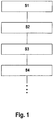
- FIG. 1 a schematic sequence of the method according to the invention is shown with the essential steps.
- a magnetically excitable core 24 having a substantially cuboidal shape 20 is provided, see also FIG. 2 ,
- the core 24 has on one side 28 parallel grooves 32.
- a core winding 40 has grooved wire portions 105 which are later disposed in the grooves 32.
- the groove wire sections 105 to be arranged in the grooves 32 and combined into a group are referred to as winding sides 36.
- the winding side 36 having core winding 40 is in a pressing tool 44 ( FIG. 6B ) so pressed that the winding sides 36 are deformed and thereby the contour of a groove 32 are adapted, step S2.
- the pressed core winding 40 is inserted with its winding sides 36 in the grooves 32 of the core 24, see also FIG. 8 .
- the core 24 together with the core winding 40 is formed into a cylindrical ring shape 52 with radially inwardly directed grooves 32.
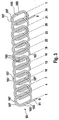
- FIG. 2 a side view of the cuboid core 24 is shown.
- the core 24 has a cuboidal shape 20 with end faces 56 which are facing away from each other.
- the end faces 56 are connected to each other by a back surface 60 and a groove surface 64.
- the two end surfaces 56, the back surface 60 and the groove surface 64 define a rectangular core cross-section;
- the core 24 has two ends 61 each having an end surface 68.
- the core 24 has a total of thirty-six grooves 32, all of which are aligned parallel to each other and arranged in a common plane.
- the grooves 32 are all open in the same direction and terminate in groove openings 72, all of which lie in the groove surface 64.
- the grooves 32 are through Parallel flanked teeth 76 limited.
- the teeth 76 have a tooth tip 78 terminating in the groove surface 64 and a tooth root 80.
- the tooth roots 80 of the teeth 76 are all in a plane parallel to the dorsal surface 60.
- the teeth 76 have a cross-sectional or profile shape 82, so that the teeth 76 extend parallel to the end surfaces 68.
- Each tooth head 78 has two racks 84 see also FIG. 8 extending in the cylinder ring shape 52 bent core 24 in the circumferential direction.
- Each tooth 76 is constructed symmetrically to a tooth center plane 86 which is oriented parallel to the end surfaces 68.
- Thirty-five fully formed teeth 76 are disposed between the two half teeth 88 so that a total of thirty-six grooves 32 and in the rounded state of the core 24 thirty six teeth 76 result, with one tooth formed of two bisected teeth 88
- the entire teeth 76 and the half teeth 88 are integrally connected with their Zahnfuß 80 with a core spine 89 with each other.
- the core back forms a magnetic return of all the whole and half teeth 76 and 88.
- the core winding 40 shown is a three-phase double-layered loop winding 90.
- the three-phase loop winding 90 wound from coated wire 91 consists of the first phase 93 with the connecting wires U and X, the second phase 96 with the core winding terminals V and Y and the third phase 99 the lead wires W and Z.
- the loop winding 90 is with its core winding terminal U in a groove 32 with a groove number. 1 inserted, the core winding lead wire Z is inserted into a groove 32 with a groove number 2 and the core winding lead wire V in a groove 32 with a groove number 3.
- this core winding 40 has a so-called total overwind 102, which is when inserting the core winding 40 in the Core 24 is initially not inserted in grooves 32.
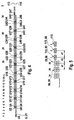
- FIG. 3 is the first phase 93 from the FIG. 2 represented in a basically the same design.
- the first phase 93 like the other two phases, consists of slot wire sections 105 and connecting wires 107 connecting these respective slot wire sections 105.
- the numbers 1 to 34 shown below the illustration of the first phase 93 indicate which slot wire sections 105 in which slots with the slot number 1 to 34 or 1 come to rest or be inserted.
- FIG. 4 is a cross-sectional view of all three phases 93, 96 and 99 as shown in FIG. 2 are shown, but only by way of example, the first phase 93 is designated.
- the other two phases 96 and 99 are made analogously.
- the numbers 1 to 36 and 3 indicate the slot numbers.
- a groove wire section 105 is arranged in a position corresponding to the groove number 1, U1, in a first step from the end of the phase U.
- the connecting wire 107 not shown, connects, which extends to the position of the groove 32 with the groove number 4.
- the winding is continued with the grooved wire section 105, U2.
- FIG. 5 is fragmentary and enlarged the range of winding sides 36 shown, which are inserted into the grooves 32 with the groove numbers 34, 35 and 36, and the individual winding overhangs 115 of the three phases 93, 96 and 99.
- a distance d1 between a winding side 36 of second phase 96 and the winding side 36 of the third phase 99 corresponds to the distance between two grooves 32 in the parallelepiped state of the core 24, see also FIG. 2 .
- the distance between the winding side 36 of the third phase 99 and the individual and first winding overhang 115 of the first phase 93 is denoted by d2.
- This distance denotes the distance between the last winding side 36 to be inserted into the core 24 before the round bending and the first winding overhang 115 which can no longer be inserted into the flat core 24.
- the distance d2 is greater than the distance d1.
- the distance between the individual winding overhangs 115 of the three phases 93, 96 and 99 with each other corresponds to the distance d1.
- FIG. 6A the cross section of a single winding side 36 is shown.
- the cross section of a single winding side 36 initially consists of the cross sections of individual groove wire sections 105, which are initially arranged more or less randomly within a certain envelope surface 118. Opposite the representation in the Figures 3 . 4 and 5 here more loops or turns have been wound.
- the winding sides 36 are deformed before insertion into the grooves 32 of the core 24 in a pressing tool so that the envelope surface 118 finally assumes the groove shape 119 of the pressing tool 44, see also FIG. 6B ,
- the winding side 36 is initially loose in the groove shape 119 of the pressing tool 44 according to the direction of the arrow in FIG. 6B inserted.
- a punch 120 presses the winding side 36 into the groove shape 119 and thereby forms the winding side 36 in such a plastic manner that it permanently assumes the groove shape 119 as the outermost envelope surface 118.
- the groove shape 119 of the pressing tool 44 may be made to correspond to the cross-sectional shape of the grooves 32 after bending.
- the groove shape 119 corresponds to the groove cross-sectional shape of the grooves 32 less at least a portion of the material thickness d iso an insulating layer 123, see also Figures 6C and 6D such as FIG. 8 ,
- the total winding overhang 102 is in the height of the second layer 112.
- the individual winding overhangs 115 have undersides which are later directed to the first layer 110. These undersides of the individual winding overhangs 115 are raised beyond the second layer 112 by the pressing in the pressing tool 44 and lie on a curve K which lies within the later diameter of the later round core 24.
- the core winding 40 After pressing and forming the winding sides 36 of the core winding 40, the core winding 40 is inserted with the winding sides 36 in the lined with the insulating material 123 grooves 32, FIG. 8 ,
- the preassembled module formed from the core 24, the insulating material 123 and the core winding 44, is converted in the next method step S4 into a cylindrical ring shape 52 with radially inwardly directed grooves 32. It starts with the half tooth 88, which borders on the groove 32 with the groove number 36.
- the half tooth 88 is relatively bent in a tool to the nearest tooth 76 between the grooves 32 with the groove numbers 35 and 36, so that the tooth heads 78 approach each other and the groove openings 72 are reduced in size.
- a back portion 140 between the half tooth 88 and the tooth 76 bent between the grooves 32 with the groove numbers 35 and 36 so that the angle between the tooth 76 and the back portion 140 is reduced the same applies to the half tooth 88.
- This forming process is continued so far until finally the tooth 76 between the Grooves 32 with the groove numbers 3 and 4 to the tooth 76 between the grooves 32 with the groove numbers 2 and 3 is bent.
- the three winding overhangs 115 of the three phases 93, 96 and 99 must be inserted into the grooves 32 with the groove numbers 3, 2 and 1.
- the individual winding overhangs 115 are inserted or inserted respectively by means of a punch 126 into the grooves 32 with the groove numbers 3, 2 and 1.
- the already compressed core winding 40 or its winding sides 36 is folded before insertion into the core 24 on the sides with the insulating layer 123 and optionally stuck, which later lies in Nutground.
- the slot closure foil 124 is inserted into the grooves 32 as previously via the punches 126 and 127 equipped with slot closure foils 124 with the winding overhangs 115.
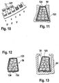
- Another variant provides for the pressed winding sides 36 to be placed in a groove 32 with a one-piece insulating layer 123 prior to insertion, FIG. 12 , In the embodiment shown therein, the insulating layer 123 is placed around the winding side 36 so that two ends 130 of the insulating layer 123 overlap and are glued together between the two adjacent surfaces of the ends.
- the entire core winding 40 is placed only after the wrapping of the winding sides 36 with the insulating layer 123 in the grooves 32 of the core 24, FIG. 13 ,
- FIG. 14 is a simple loop winding spatially represented.
- This loop winding in turn represents the first phase 93 of a core winding 40.
- This loop winding is wound starting from a position of a groove 32 having the groove number 1, so that a first loop is wound in the grooves 32 with the groove numbers 1 and 4 and finally in a relation to the Nutabriol three-step further coils are arranged.
- the first phase 93 ends with the end X in the groove 32 with the groove number 34.
- a correspondingly constructed second phase 96 is transferred to a groove 32 with the groove number 2 up to a groove 32 with the groove number 35 to form a core winding 40
- the same is done with a third phase 99, starting in the groove with the number 3 to the groove with the groove number 36.
- a core winding 40 constructed in this way has no overall development overhang 102.
- a core 24 is shown with seventy-two slots.
- a first phase 93 starting from a groove 32 with the groove number 1, in the grooves 1 and 7 wound to be wound around the grooves 2 and 8 after a certain number of turns.
- a coil connecting wire is used to wind another coil or into the slots 14 and 20 and so on, until finally, after a total of eight further coils, the phase winding 93 returns to the slot numbered 68 the wire is guided out of the core 24.
- the second phase 96 is started to finally lead in the groove with the number 70, the wire of the second phase 96 from the core 24 again.
- the winding of the third phase 99 starts in the groove with the number 5 and ends in the groove with the number 72.
- the first phase 93 is shown in the form of a distributed wave winding 135.
- the wire 91 is guided into the groove 4 via a connecting wire section 107, from there again via a further connecting wire section 107 into the groove 7 and, as in FIG. 16 shown, further wound until a first winding overhang 115 arises in a position corresponding to the groove 1. From there, the grooves 34 to 4 are wound back.
- a second phase winding 96 is wound in an analogous manner, starting from the groove 2 to the groove 2, and a winding overhang 115 formed there back to the groove 5, a third phase, starting in the groove 3, to a winding overhang 115 in the groove 32 with the groove number 3 and from there back into the groove 32 with the groove number 6 wound.
- a core 24 with a core winding 40 designed as a distributed wave winding 35 is also suitable for the method according to the invention.
- the core 24 is provided.
- the winding 40 is either wrapped with the wire 91 or inserted a prefabricated winding 40 in the grooves 32.
- the winding 40 is not yet pressed.
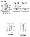
- a guide element 173 is placed on the later radially inwardly directed side 28 of the core 24 so that a constant distance is set between the guide elements 173.
- a forming die 176 with an inner contour 179 is then guided by the two guide elements 173 guided on the winding side 115.
- the individual grooved wire sections 105 of the winding side 115 are thereby forced into the inner contour 179 and reshaped so that the cross sections of the winding sides 115 after the forming corresponds to the cross section of a groove 32 after the round bending of the core 24, FIG. 17A, FIG. 17B ,
- an insulating layer 123 may be introduced beforehand as required.
- the forming punch 176 is removed again from the groove 32, the guide elements 173 are lifted off the core 24, Figure 17C ,
- This core 24 with winding 40 is then as in FIG. 9 or 10 shown and described in the further process steps processed.
- wire 91 whose largest cross-sectional dimension is greater than the width of the groove opening 72 in the circumferential direction of the core 24, if it is still in cuboid shape 20. If such a winding with an endless wire 91, for example, wire 91 having a rectangular wire cross section as used for windings called rod windings, wound, as is performed in the already described three winding designs, so inserting the core winding 40 is not possible per se , To remedy this, the core 24 is bent over its back surface 60 before inserting the core winding 40 so that the groove openings 72 expand and the core winding 40 can be inserted.
- the embodiment of the Figures 18A and 18B is not limited to the use of wires of the corresponding cross-sectional dimensions. Rather, this also applies to core windings 40 with winding sides 36, which are pressed so that they are not due to their width in the circumferential direction per se are not inserted into the groove opening 72, but only after the widening of the groove opening after bending the core 24 via its back surface 60th
- a so-called baked enamel can be used to fix the winding sides 36. This is for example possible because one already with such a paint treated wire 91 is used, the varnish layer in the pressing tool 44 heated and at least assumes a sticky state, so that the wires 91 can adhere to each other and are firmly bonded together after cooling and solidification and easy to continue processing.
- the electrically effective slot fill factor is defined here as the area cross section ratio of the sum of all cross sections arranged in a groove 32 of the electrically effective part of the slot wire sections 105 with respect to the cross section of the slot 32 after the round bend.
- the electrically effective Nuthelltex of at least 55%. This lower limit represents a minimum requirement for the electrical efficiency.
- An upper limit of 75% is technically just possible.
- a higher slot fill factor results in such high forces when pressing the winding sides 36 that a layer of paint on the wires 91 will be damaged, thus making short circuits in the core winding 40 unusable.
- a good compromise taking into account the manufacturing tolerances and technical feasibility is given with a groove fill factor in a range between 57% and 70%.
- a stator 150 is shown of a core 24 constructed of fins 153 with a simple loop winding as a core winding 40.
- a joint 156 formed from the two abutting end surfaces 68 of the round bent core 24, shown.
- a weld 160 is set at the joint 156 to connect both ends 61 of the core 24 firmly together.
- FIG. 20 a symbolic representation of an electric machine 140 with the stand 150 according to the invention is shown.
Landscapes
- Engineering & Computer Science (AREA)
- Power Engineering (AREA)
- Manufacturing & Machinery (AREA)
- Manufacture Of Motors, Generators (AREA)
- Iron Core Of Rotating Electric Machines (AREA)
- Windings For Motors And Generators (AREA)
Applications Claiming Priority (3)
| Application Number | Priority Date | Filing Date | Title |
|---|---|---|---|
| DE10002385 | 2000-01-20 | ||
| DE10002385 | 2000-01-20 | ||
| PCT/DE2001/000244 WO2001054254A1 (de) | 2000-01-20 | 2001-01-22 | Verfahren zur herstellung eines magnetisch erregbaren kerns mit kernwicklung für eine elektrische maschine |
Publications (2)
| Publication Number | Publication Date |
|---|---|
| EP1171945A1 EP1171945A1 (de) | 2002-01-16 |
| EP1171945B1 true EP1171945B1 (de) | 2016-03-30 |
Family
ID=7628187
Family Applications (1)
| Application Number | Title | Priority Date | Filing Date |
|---|---|---|---|
| EP01907382.4A Expired - Lifetime EP1171945B1 (de) | 2000-01-20 | 2001-01-22 | Verfahren zur herstellung eines magnetisch erregbaren kerns mit kernwicklung für eine elektrische maschine |
Country Status (13)
| Country | Link |
|---|---|
| US (1) | US7600311B2 (ja) |
| EP (1) | EP1171945B1 (ja) |
| JP (2) | JP5506125B2 (ja) |
| KR (1) | KR100928160B1 (ja) |
| CN (1) | CN100466421C (ja) |
| AU (1) | AU768932B2 (ja) |
| BR (1) | BRPI0104099B1 (ja) |
| DE (1) | DE10190175D2 (ja) |
| ES (1) | ES2578652T3 (ja) |
| MX (1) | MXPA01009479A (ja) |
| RU (1) | RU2267215C2 (ja) |
| WO (1) | WO2001054254A1 (ja) |
| ZA (1) | ZA200107650B (ja) |
Families Citing this family (60)
| Publication number | Priority date | Publication date | Assignee | Title |
|---|---|---|---|---|
| DE10115186A1 (de) * | 2001-03-27 | 2002-10-24 | Rexroth Indramat Gmbh | Gekühltes Primärteil oder Sekundärteil eines Elektromotors |
| GB2389717B (en) * | 2002-01-24 | 2004-07-28 | Visteon Global Tech Inc | Automotive alternator stator assembly and winding method |
| DE10245691A1 (de) * | 2002-09-30 | 2004-04-08 | Robert Bosch Gmbh | Ständer für eine elektrische Maschine |
| DE10328956A1 (de) | 2003-06-27 | 2005-01-20 | Elmotec Statomat Vertriebs Gmbh | Verfahren und Vorrichtung zum Einführen von Wellenwicklungen in Rotor- und Statorblechpakete elektrischer Maschinen |
| DE10328955B4 (de) * | 2003-06-27 | 2008-07-24 | Elmotec Statomat Vertriebs Gmbh | Verfahren und Vorrichtung zum Formen von Wellenwicklungen für Rotor- und Statorblechpakete elektrischer Maschinen |
| DE10329576A1 (de) * | 2003-06-30 | 2005-02-24 | Robert Bosch Gmbh | Verfahren zum Herstellen einer zweischichtigen Schleifenwicklung |
| DE10329572A1 (de) * | 2003-06-30 | 2005-01-20 | Robert Bosch Gmbh | Verfahren zur Herstellung eines elektromagnetisch erregbaren Kerns |
| JP2005124319A (ja) * | 2003-10-17 | 2005-05-12 | Mitsubishi Electric Corp | 回転電機の固定子及びその製造方法 |
| DE10361858A1 (de) | 2003-12-30 | 2005-07-28 | Robert Bosch Gmbh | Ständer für eine elektrische Maschine |
| DE10361857A1 (de) | 2003-12-30 | 2005-07-28 | Robert Bosch Gmbh | Verfahren zur Herstellung eines Ständers sowie danach hergestellter Ständer |
| US7081697B2 (en) * | 2004-06-16 | 2006-07-25 | Visteon Global Technologies, Inc. | Dynamoelectric machine stator core with mini caps |
| SE0401826D0 (sv) | 2004-07-09 | 2004-07-09 | Trimble Ab | Method of preparing a winding for an n-phase motor |
| DE102004058659A1 (de) | 2004-12-06 | 2006-06-22 | Robert Bosch Gmbh | Fertigungseinrichtung und Verfahren zur Herstellung eines elektromagnetischen Elemensts für eine elektrische Maschine |
| DE102005048094A1 (de) * | 2005-09-30 | 2007-04-05 | Robert Bosch Gmbh | Verfahren und Vorrichtung zur Herstellung einer Wicklung für elektrische Maschinen |
| DE102005063271A1 (de) * | 2005-12-30 | 2007-07-19 | Robert Bosch Gmbh | Generator, insbesondere für Kraftfahrzeuge |
| DE102006016249A1 (de) * | 2006-03-31 | 2007-10-04 | Robert Bosch Gmbh | Stator für eine Elektromaschine und Verfahren zur Herstellung |
| DE202006007619U1 (de) * | 2006-05-11 | 2007-09-13 | Dr. Fritz Faulhaber Gmbh & Co. Kg | Glockenankerspule |
| JP5040303B2 (ja) * | 2006-12-28 | 2012-10-03 | 株式会社日立製作所 | 回転電機 |
| DE102008006641A1 (de) | 2007-01-29 | 2008-12-24 | Robert Bosch Gmbh | Elektrische Maschine mit einem Ständer, sowie Verfahren zur Herstellung einer elektrischen Maschine mit einem Ständer |
| DE102007034322A1 (de) | 2007-07-24 | 2009-01-29 | Robert Bosch Gmbh | Verfahren zur Herstellung einer vorzugsweise mehrphasigen Wicklung für den Stator einer elektrischen Maschine |
| DE102007036313A1 (de) | 2007-07-31 | 2009-02-05 | Robert Bosch Gmbh | Verfahren zur Herstellung einer Wicklung für den Stator einer elektrischen Maschine |
| DE102007036263A1 (de) | 2007-08-02 | 2009-02-05 | Robert Bosch Gmbh | Elektrische Maschine und Verfahren zu seiner Herstellung |
| DE102007038527A1 (de) | 2007-08-16 | 2009-02-19 | Robert Bosch Gmbh | Verfahren zum Herstellen eines Ständers einer elektrischen Maschine |
| US7876016B2 (en) * | 2007-11-15 | 2011-01-25 | Sundyne Corporation | Stator winding method and apparatus |
| JP4705949B2 (ja) * | 2007-12-12 | 2011-06-22 | 本田技研工業株式会社 | 固定子の製造方法 |
| CN102246398B (zh) * | 2008-12-19 | 2014-09-24 | 罗伯特·博世有限公司 | 制作多相系统分布叠绕组的方法 |
| DE102009055043A1 (de) | 2008-12-19 | 2010-06-24 | Robert Bosch Gmbh | Verfahren zur Herstellung einer verteilten Schleifenwicklung für mehrphasige Systeme |
| DE102009024230A1 (de) * | 2009-05-29 | 2010-12-02 | Robert Bosch Gmbh | Verfahren zur Herstellung einer Ständerwicklung einer elektrischen Maschine, insbesondere zur Herstellung eines Wechselstromgenerators |
| DE102009024231A1 (de) | 2009-05-29 | 2010-12-09 | Robert Bosch Gmbh | Verfahren zur Herstellung einer Ständerwicklung einer elektrischen Maschine, insbesondere eines Wechselstromgenerators |
| DE102010042369A1 (de) | 2010-10-13 | 2012-04-19 | Robert Bosch Gmbh | Elektrische Maschine |
| US9564791B2 (en) * | 2010-12-01 | 2017-02-07 | Robert Bosch Gmbh | Method for producing a stator winding of an electric machine, in particular for producing an AC generator |
| DE102010053716A1 (de) | 2010-12-01 | 2012-06-06 | Robert Bosch Gmbh | Verfahren zum Prägen von Spulenseiten einer Ständerwicklung |
| EP2654182B1 (en) * | 2010-12-14 | 2019-02-13 | Mitsubishi Electric Corporation | Rotating electrical machine for vehicle, and method for manufacturing stator for use in rotating electrical machine |
| DE102011085654A1 (de) | 2011-11-03 | 2013-05-08 | Continental Automotive Gmbh | Verfahren zur Herstellung eines runden Stators und Rolliereinrichtung |
| US9467010B2 (en) | 2011-11-17 | 2016-10-11 | Remy Technologies, L.L.C. | Method of winding a stator core with a continuous conductor having a rectangular cross-section and a stator core |
| US8745847B2 (en) | 2011-11-17 | 2014-06-10 | Remy Technologies, L.L.C. | Method of P-forming a continuous conductor having a rectangular cross section and a stator including a stator winding formed from a P-formed conductor having a rectangular cross-section |
| US8789259B2 (en) | 2011-11-17 | 2014-07-29 | Remy Technologies, L.L.C. | Method of winding a stator core with a continuous conductor having a rectangular cross-section and a stator core |
| US9118225B2 (en) * | 2012-08-24 | 2015-08-25 | Caterpillar Inc. | Coil with twisted wires and stator assembly of a rotary electric machine |
| US20140208579A1 (en) * | 2013-01-30 | 2014-07-31 | Victory Industrial Corporation | Manufacturing Method of a Stator of an Alternator |
| DE102013212407A1 (de) | 2013-06-27 | 2014-12-31 | Robert Bosch Gmbh | Elektrische Maschine |
| DE102013214106A1 (de) * | 2013-07-18 | 2015-01-22 | Bayerische Motoren Werke Aktiengesellschaft | Verfahren zur Herstellung einer Erregerwicklung für eine elektrische Maschine, Erregerwicklung und elektrische Maschine |
| DE102013222643A1 (de) * | 2013-11-07 | 2015-05-07 | Robert Bosch Gmbh | Flachpaket zur Herstellung eines Stators |
| FR3020521B1 (fr) * | 2014-04-29 | 2016-06-03 | Nicolas Langlard | Stator de machine electrique tournante muni d'un bobinage optimise |
| EP2963773B1 (en) * | 2014-07-01 | 2019-10-02 | Victory Industrial Corporation | Vehicle alternating-current generator |
| DE102014221938A1 (de) | 2014-10-28 | 2016-04-28 | Robert Bosch Gmbh | Elektrische Maschine mit einer Nutisolation und Verfahren zu deren Herstellung |
| DE102014226319A1 (de) | 2014-12-17 | 2016-06-23 | Robert Bosch Gmbh | Vorrichtung zum Isolieren eines elektromagnetisch erregbaren Ständereisens und Halbzeug für eine elektrische Maschine |
| DE102014226253A1 (de) | 2014-12-17 | 2016-06-23 | Robert Bosch Gmbh | Vorrichtung mit einem elektromagnetisch erregbaren Kern und einer Isolationsschicht und Verfahren zum Befestigen einer Isolationsschicht an einem elektromagnetisch erregbaren Kern |
| DE102014226526A1 (de) | 2014-12-19 | 2016-06-23 | Robert Bosch Gmbh | Vorrichtung mit einem elektromagnetisch erregbaren Kern, in dem eine isolierte Wicklung eingelegt ist, sowie Verfahren zum Isolieren einer Wicklung |
| DE102015200415A1 (de) | 2015-01-14 | 2016-07-14 | Robert Bosch Gmbh | Stator einer elektrischen Maschine und Verfahren zur Herstellung des Stators |
| JP6203785B2 (ja) * | 2015-06-25 | 2017-09-27 | ファナック株式会社 | 8の字状の連結コイルを有する電動機とその製造方法 |
| US10110080B2 (en) | 2015-11-30 | 2018-10-23 | Caterpillar Inc. | Coil and stator assembly of a rotary electric machine |
| DE102015225758A1 (de) | 2015-12-17 | 2017-06-22 | Robert Bosch Gmbh | Verfahren zum Beschichten eines elektromagnetisch erregbaren Kerns |
| DE102016123068A1 (de) | 2016-11-30 | 2018-05-30 | Dr. Ing. H.C. F. Porsche Aktiengesellschaft | Rotierende elektrische Maschine und besonders angepasstes Verfahren zum Herstellen einer solchen |
| DE102017209792B4 (de) | 2017-06-09 | 2023-10-05 | Fraunhofer-Gesellschaft zur Förderung der angewandten Forschung e.V. | Halbzeug für eine elektrotechnische Spule sowie Verfahren und Vorrichtung zur Herstellung desselben |
| DE102017213151A1 (de) | 2017-07-31 | 2019-01-31 | Fraunhofer-Gesellschaft zur Förderung der angewandten Forschung e.V. | Elektrotechnische Spule sowie Verfahren und Halbzeug zur Herstellung derselben |
| DE102017213106B4 (de) | 2017-07-31 | 2024-05-29 | Fraunhofer-Gesellschaft zur Förderung der angewandten Forschung e.V. | Verfahren zur Herstellung einer elektrotechnischen Spule |
| DE102018104844A1 (de) * | 2018-03-02 | 2019-09-05 | Aumann Espelkamp Gmbh | Verfahren und Vorrichtung zum Herstellen einer Anordnung für eine Spule mit einer verteilten Spulenwicklung einer elektrodynamischen Maschine, Anordnung und Spule |
| DE102019132681A1 (de) * | 2019-08-08 | 2021-02-11 | stoba e-Systems GmbH | Elektromotor und Stator mit mehrfachbelegten Nuten |
| FR3126567A1 (fr) * | 2021-09-01 | 2023-03-03 | Valeo Equipements Electriques Moteur | Procédé de bobinage d'un stator de machine électrique tournante à multi-encoches par pôle et par phase |
| DE102022101619A1 (de) * | 2022-01-25 | 2023-07-27 | Schaeffler Technologies AG & Co. KG | Verfahren zur Umformung einer Wellenwicklung und eine nach dem Verfahren umgeformte Wellenwicklung |
Family Cites Families (29)
| Publication number | Priority date | Publication date | Assignee | Title |
|---|---|---|---|---|
| US1756672A (en) | 1922-10-12 | 1930-04-29 | Allis Louis Co | Dynamo-electric machine |
| US2607816A (en) | 1947-01-29 | 1952-08-19 | Stewart Warner Corp | Electric motor |
| DE1002385C2 (de) | 1953-12-14 | 1957-07-18 | Siemens Ag | Stellwerk mit elektrischen Verschluessen, insbesondere Gleisbildstellwerk |
| US4102040A (en) | 1975-07-03 | 1978-07-25 | Societe Anonyme Pour L'equipement Electrique Des Vehicules S.E.V. Marchal | Method of manufacturing a curved component of a magnetic circuit |
| JPS5694939A (en) | 1979-12-28 | 1981-07-31 | Shibaura Eng Works Co Ltd | Rotor |
| JPS59103549A (ja) | 1982-12-01 | 1984-06-15 | Hitachi Ltd | コイルの挿入装置 |
| JPS59122331A (ja) | 1982-12-27 | 1984-07-14 | Hitachi Ltd | 回転電機の電機子及びその製造方法 |
| DE3408394A1 (de) | 1984-03-08 | 1985-09-19 | Robert Bosch Gmbh, 70469 Stuttgart | Elektrischer generator, insbesondere lichtmaschine fuer fahrzeuge |
| JPS63161845A (ja) * | 1986-12-22 | 1988-07-05 | Nippon Denso Co Ltd | コイル挿入装置 |
| JPS63194543A (ja) | 1987-02-09 | 1988-08-11 | Hitachi Ltd | 車両用交流発電機の固定子及びその製造方法 |
| JPH01252141A (ja) | 1988-03-31 | 1989-10-06 | Shibaura Eng Works Co Ltd | 電動機 |
| JP2888142B2 (ja) | 1993-11-08 | 1999-05-10 | 三菱電機株式会社 | 回転電動機並びにその製造方法 |
| JPH03155346A (ja) * | 1989-11-08 | 1991-07-03 | Toshiba Corp | 回転電機の固定子鉄心 |
| JPH04100968A (ja) * | 1990-08-07 | 1992-04-02 | Iwasaki Tsuneo | 長尺布帛の継目検出装置 |
| US5212419A (en) * | 1992-01-10 | 1993-05-18 | Fisher Electric Motor Technology, Inc. | Lightweight high power electromotive device |
| US5382859A (en) * | 1992-09-01 | 1995-01-17 | Unique Mobility | Stator and method of constructing same for high power density electric motors and generators |
| JPH07222408A (ja) | 1994-02-03 | 1995-08-18 | Nippon Steel Corp | モータの電機子あるいは界磁子の製造法 |
| JPH08223840A (ja) * | 1995-02-17 | 1996-08-30 | Toyota Motor Corp | コイル用巻線材およびその製造方法 |
| JP3346968B2 (ja) * | 1995-10-06 | 2002-11-18 | 三菱電機株式会社 | 交流回転電機の固定子製造方法 |
| JPH09149608A (ja) * | 1995-11-20 | 1997-06-06 | Toyota Motor Corp | 導線束成形装置 |
| JPH09168261A (ja) * | 1995-12-14 | 1997-06-24 | Hitachi Ltd | コイルの製造方法とその装置 |
| JP3722539B2 (ja) * | 1996-02-09 | 2005-11-30 | 黒田精工株式会社 | 環状積層鉄心の製造方法及び順送り金型装置 |
| PT1011893E (pt) * | 1996-11-15 | 2004-12-31 | Globe Motors Inc | Ferramenta de formacao de fio de estator |
| JP3514939B2 (ja) * | 1997-03-27 | 2004-04-05 | 株式会社日立製作所 | 電動機およびステータの製造方法 |
| JPH10285882A (ja) * | 1997-04-09 | 1998-10-23 | Hitachi Ltd | 絶縁コイルの製造方法並びに電気機械及び回転電気機械 |
| FI112412B (fi) * | 1997-04-18 | 2003-11-28 | Kone Corp | Menetelmä sähkökoneen käämityksen valmistamiseksi |
| JP3738528B2 (ja) | 1997-06-19 | 2006-01-25 | 株式会社デンソー | 回転電機のステータ及びその製造方法 |
| JPH1132457A (ja) * | 1997-07-10 | 1999-02-02 | Toyota Motor Corp | 回転電機のステータ |
| JP3735197B2 (ja) * | 1998-02-27 | 2006-01-18 | 株式会社日立製作所 | コイル成形体の製造方法およびそれに用いる金型 |
-
2001
- 2001-01-22 RU RU2001126556/11A patent/RU2267215C2/ru not_active IP Right Cessation
- 2001-01-22 EP EP01907382.4A patent/EP1171945B1/de not_active Expired - Lifetime
- 2001-01-22 AU AU35351/01A patent/AU768932B2/en not_active Ceased
- 2001-01-22 US US09/937,167 patent/US7600311B2/en not_active Expired - Fee Related
- 2001-01-22 BR BRPI0104099A patent/BRPI0104099B1/pt not_active IP Right Cessation
- 2001-01-22 DE DE10190175T patent/DE10190175D2/de not_active Expired - Lifetime
- 2001-01-22 ES ES01907382.4T patent/ES2578652T3/es not_active Expired - Lifetime
- 2001-01-22 JP JP2001553641A patent/JP5506125B2/ja not_active Expired - Fee Related
- 2001-01-22 MX MXPA01009479A patent/MXPA01009479A/es active IP Right Grant
- 2001-01-22 WO PCT/DE2001/000244 patent/WO2001054254A1/de active Application Filing
- 2001-01-22 CN CNB018000886A patent/CN100466421C/zh not_active Expired - Fee Related
- 2001-01-22 KR KR1020017011794A patent/KR100928160B1/ko active IP Right Grant
- 2001-09-17 ZA ZA200107650A patent/ZA200107650B/en unknown
-
2012
- 2012-06-11 JP JP2012132123A patent/JP5599432B2/ja not_active Expired - Fee Related
Also Published As
| Publication number | Publication date |
|---|---|
| DE10190175D2 (de) | 2002-05-29 |
| RU2267215C2 (ru) | 2005-12-27 |
| BRPI0104099B1 (pt) | 2016-03-08 |
| CN1358345A (zh) | 2002-07-10 |
| WO2001054254A1 (de) | 2001-07-26 |
| JP2012196133A (ja) | 2012-10-11 |
| US7600311B2 (en) | 2009-10-13 |
| CN100466421C (zh) | 2009-03-04 |
| BR0104099A (pt) | 2001-12-26 |
| ZA200107650B (en) | 2002-12-17 |
| AU768932B2 (en) | 2004-01-08 |
| US20030071534A1 (en) | 2003-04-17 |
| MXPA01009479A (es) | 2002-06-04 |
| JP5506125B2 (ja) | 2014-05-28 |
| EP1171945A1 (de) | 2002-01-16 |
| JP5599432B2 (ja) | 2014-10-01 |
| AU3535101A (en) | 2001-07-31 |
| ES2578652T3 (es) | 2016-07-29 |
| KR100928160B1 (ko) | 2009-11-25 |
| JP2003520559A (ja) | 2003-07-02 |
| KR20020002405A (ko) | 2002-01-09 |
Similar Documents
| Publication | Publication Date | Title |
|---|---|---|
| EP1171945B1 (de) | Verfahren zur herstellung eines magnetisch erregbaren kerns mit kernwicklung für eine elektrische maschine | |
| DE10321221B4 (de) | Herstellungsverfahren eines Statorkerns für eine dynamoelektrische Maschine | |
| DE60210572T2 (de) | Wicklung für eine elecktrische Rotationsmaschine, Verfahren zur Herstellung dieser Wicklung, und Verfahren zur Herstellung einer elecktrischen Rotationsmaschine mit solcher Wicklung | |
| DE102012201698A1 (de) | Spule, Stator und Verfahren zum Herstellen der Spule | |
| DE19851363A1 (de) | Verfahren zur Herstellung eines Stators für einen Elektromotor | |
| DE3803752A1 (de) | Staender fuer einen kraftfahrzeug-drehstromgenerator und herstellungsverfahren dafuer | |
| DE4031276A1 (de) | Staender fuer elektrische maschinen und verfahren zu seiner herstellung | |
| DE102011008092A1 (de) | Ständer für einen Elektromotor | |
| EP1586155B1 (de) | Ständerblechpaket | |
| EP1494338B1 (de) | Herstellungsverfahren eines Kerns einer elektrischen Maschine | |
| DE4122076A1 (de) | Verfahren zur herstellung einer statorwicklung mit profilleitern fuer elektrische maschinen | |
| WO2018041836A1 (de) | Verfahren zum herstellen und einbringen einer drahtwicklung | |
| EP1494337B1 (de) | Verfahren zum Herstellen einer zweischichtigen Schleifenwicklung | |
| EP1638186A1 (de) | Stator einer elektrischen Maschine und Verfahren für seiner Herstellung | |
| EP1087497B1 (de) | Stator für einen als Innenläufermotor ausgebildeten Elektromotor | |
| DE102016207944A1 (de) | Paketsystem für eine elektrische Maschine, elektrische Maschine und Verfahren zur Herstellung des Paketsystems | |
| DE102010043976A1 (de) | Komponente zum Herstellen einer Maschinenkomponente für eine elektrische Maschine | |
| DE10239730A1 (de) | Ständer für elektrische Drehfeldmaschinen | |
| EP1915812B1 (de) | Elektrische maschine mit mehretagiger wicklung | |
| EP3167540B1 (de) | Verfahren zum herstellen einer elektrischen maschine mit formspulen sowie elektrische maschine und herstellungswerkzeug | |
| DE4244694C2 (de) | Verfahren zur Herstellung einer mehrphasigen elektrischen Maschine | |
| DE10121043A1 (de) | Ringförmiges elektromagnetisches Element für eine elektrische Maschine und Verfahren zur Herstellung des Elements | |
| DE3638540C2 (ja) | ||
| EP4362299A1 (de) | Verfahren und werkzeug zur herstellung einer kompakten spulenbaugruppe eines elektromotors für eine bohrlochpumpe | |
| DE102021124996A1 (de) | Verfahren zur Herstellung einer Wicklung für einen Stator einer elektrischen Rotationsmaschine, Stator, Verfahren zur Herstellung des Stators und elektrische Rotationsmaschine |
Legal Events
| Date | Code | Title | Description |
|---|---|---|---|
| PUAI | Public reference made under article 153(3) epc to a published international application that has entered the european phase |
Free format text: ORIGINAL CODE: 0009012 |
|
| AK | Designated contracting states |
Kind code of ref document: A1 Designated state(s): AT BE CH CY DE DK ES FI FR GB GR IE IT LI LU MC NL PT SE TR |
|
| AX | Request for extension of the european patent |
Free format text: AL;LT;LV;MK;RO;SI |
|
| 17P | Request for examination filed |
Effective date: 20020128 |
|
| RBV | Designated contracting states (corrected) |
Designated state(s): DE ES FR GB IT SE |
|
| 17Q | First examination report despatched |
Effective date: 20090610 |
|
| GRAP | Despatch of communication of intention to grant a patent |
Free format text: ORIGINAL CODE: EPIDOSNIGR1 |
|
| INTG | Intention to grant announced |
Effective date: 20150907 |
|
| GRAS | Grant fee paid |
Free format text: ORIGINAL CODE: EPIDOSNIGR3 |
|
| GRAA | (expected) grant |
Free format text: ORIGINAL CODE: 0009210 |
|
| AK | Designated contracting states |
Kind code of ref document: B1 Designated state(s): DE ES FR GB IT SE |
|
| REG | Reference to a national code |
Ref country code: GB Ref legal event code: FG4D Free format text: NOT ENGLISH |
|
| REG | Reference to a national code |
Ref country code: DE Ref legal event code: R081 Ref document number: 50116544 Country of ref document: DE Owner name: SEG AUTOMOTIVE GERMANY GMBH, DE Free format text: FORMER OWNER: ROBERT BOSCH GMBH, 70469 STUTTGART, DE |
|
| REG | Reference to a national code |
Ref country code: DE Ref legal event code: R096 Ref document number: 50116544 Country of ref document: DE |
|
| REG | Reference to a national code |
Ref country code: ES Ref legal event code: FG2A Ref document number: 2578652 Country of ref document: ES Kind code of ref document: T3 Effective date: 20160729 |
|
| PG25 | Lapsed in a contracting state [announced via postgrant information from national office to epo] |
Ref country code: SE Free format text: LAPSE BECAUSE OF FAILURE TO SUBMIT A TRANSLATION OF THE DESCRIPTION OR TO PAY THE FEE WITHIN THE PRESCRIBED TIME-LIMIT Effective date: 20160330 |
|
| REG | Reference to a national code |
Ref country code: DE Ref legal event code: R097 Ref document number: 50116544 Country of ref document: DE |
|
| REG | Reference to a national code |
Ref country code: FR Ref legal event code: PLFP Year of fee payment: 17 |
|
| PLBE | No opposition filed within time limit |
Free format text: ORIGINAL CODE: 0009261 |
|
| STAA | Information on the status of an ep patent application or granted ep patent |
Free format text: STATUS: NO OPPOSITION FILED WITHIN TIME LIMIT |
|
| 26N | No opposition filed |
Effective date: 20170103 |
|
| PGFP | Annual fee paid to national office [announced via postgrant information from national office to epo] |
Ref country code: GB Payment date: 20170125 Year of fee payment: 17 |
|
| REG | Reference to a national code |
Ref country code: DE Ref legal event code: R081 Ref document number: 50116544 Country of ref document: DE Owner name: SEG AUTOMOTIVE GERMANY GMBH, DE Free format text: FORMER OWNER: ROBERT BOSCH GMBH, 70469 STUTTGART, DE |
|
| REG | Reference to a national code |
Ref country code: FR Ref legal event code: PLFP Year of fee payment: 18 |
|
| REG | Reference to a national code |
Ref country code: ES Ref legal event code: PC2A Owner name: SEG AUTOMOTIVE GERMANY GMBH Effective date: 20180119 |
|
| REG | Reference to a national code |
Ref country code: FR Ref legal event code: TP Owner name: SEG AUTOMOTIVE GERMANY GMBH, DE Effective date: 20180315 |
|
| GBPC | Gb: european patent ceased through non-payment of renewal fee |
Effective date: 20180122 |
|
| PG25 | Lapsed in a contracting state [announced via postgrant information from national office to epo] |
Ref country code: GB Free format text: LAPSE BECAUSE OF NON-PAYMENT OF DUE FEES Effective date: 20180122 |
|
| PGFP | Annual fee paid to national office [announced via postgrant information from national office to epo] |
Ref country code: IT Payment date: 20190121 Year of fee payment: 19 Ref country code: ES Payment date: 20190205 Year of fee payment: 19 Ref country code: FR Payment date: 20190117 Year of fee payment: 19 Ref country code: DE Payment date: 20190128 Year of fee payment: 19 |
|
| REG | Reference to a national code |
Ref country code: DE Ref legal event code: R119 Ref document number: 50116544 Country of ref document: DE |
|
| PG25 | Lapsed in a contracting state [announced via postgrant information from national office to epo] |
Ref country code: DE Free format text: LAPSE BECAUSE OF NON-PAYMENT OF DUE FEES Effective date: 20200801 |
|
| PG25 | Lapsed in a contracting state [announced via postgrant information from national office to epo] |
Ref country code: IT Free format text: LAPSE BECAUSE OF NON-PAYMENT OF DUE FEES Effective date: 20200122 |
|
| REG | Reference to a national code |
Ref country code: ES Ref legal event code: FD2A Effective date: 20210604 |
|
| PG25 | Lapsed in a contracting state [announced via postgrant information from national office to epo] |
Ref country code: FR Free format text: LAPSE BECAUSE OF NON-PAYMENT OF DUE FEES Effective date: 20200131 |
|
| PG25 | Lapsed in a contracting state [announced via postgrant information from national office to epo] |
Ref country code: ES Free format text: LAPSE BECAUSE OF NON-PAYMENT OF DUE FEES Effective date: 20200123 |